EP0607612B1 - Procédé d'utilisation pour une machine de nettoyage des tuyaux et machine pour la mise en oeuvre ce procédé - Google Patents
Procédé d'utilisation pour une machine de nettoyage des tuyaux et machine pour la mise en oeuvre ce procédé Download PDFInfo
- Publication number
- EP0607612B1 EP0607612B1 EP93120906A EP93120906A EP0607612B1 EP 0607612 B1 EP0607612 B1 EP 0607612B1 EP 93120906 A EP93120906 A EP 93120906A EP 93120906 A EP93120906 A EP 93120906A EP 0607612 B1 EP0607612 B1 EP 0607612B1
- Authority
- EP
- European Patent Office
- Prior art keywords
- drive motor
- hand lever
- switch
- cleaning machine
- pipe
- Prior art date
- Legal status (The legal status is an assumption and is not a legal conclusion. Google has not performed a legal analysis and makes no representation as to the accuracy of the status listed.)
- Expired - Lifetime
Links
- 238000004140 cleaning Methods 0.000 title claims abstract description 81
- 238000000034 method Methods 0.000 title claims description 8
- 230000001965 increasing effect Effects 0.000 claims abstract description 15
- 235000014676 Phragmites communis Nutrition 0.000 claims description 5
- 230000001939 inductive effect Effects 0.000 claims description 3
- 230000005693 optoelectronics Effects 0.000 claims description 2
- 239000000696 magnetic material Substances 0.000 claims 1
- 238000011017 operating method Methods 0.000 description 7
- 230000007935 neutral effect Effects 0.000 description 6
- 230000005484 gravity Effects 0.000 description 4
- 240000003517 Elaeocarpus dentatus Species 0.000 description 3
- 230000006835 compression Effects 0.000 description 3
- 238000007906 compression Methods 0.000 description 3
- 238000006073 displacement reaction Methods 0.000 description 2
- 238000003825 pressing Methods 0.000 description 2
- 239000003990 capacitor Substances 0.000 description 1
- 230000002596 correlated effect Effects 0.000 description 1
- 230000008878 coupling Effects 0.000 description 1
- 238000010168 coupling process Methods 0.000 description 1
- 238000005859 coupling reaction Methods 0.000 description 1
- 230000000994 depressogenic effect Effects 0.000 description 1
- 238000001514 detection method Methods 0.000 description 1
- 239000013536 elastomeric material Substances 0.000 description 1
- 239000000463 material Substances 0.000 description 1
- 230000005226 mechanical processes and functions Effects 0.000 description 1
- 238000003801 milling Methods 0.000 description 1
- 230000002093 peripheral effect Effects 0.000 description 1
- 238000007789 sealing Methods 0.000 description 1
- 239000010865 sewage Substances 0.000 description 1
- 238000011144 upstream manufacturing Methods 0.000 description 1
- XLYOFNOQVPJJNP-UHFFFAOYSA-N water Substances O XLYOFNOQVPJJNP-UHFFFAOYSA-N 0.000 description 1
Images




Classifications
-
- E—FIXED CONSTRUCTIONS
- E03—WATER SUPPLY; SEWERAGE
- E03F—SEWERS; CESSPOOLS
- E03F9/00—Arrangements or fixed installations methods or devices for cleaning or clearing sewer pipes, e.g. by flushing
- E03F9/002—Cleaning sewer pipes by mechanical means
- E03F9/005—Apparatus for simultaneously pushing and rotating a cleaning device carried by the leading end of a cable or an assembly of rods
-
- B—PERFORMING OPERATIONS; TRANSPORTING
- B08—CLEANING
- B08B—CLEANING IN GENERAL; PREVENTION OF FOULING IN GENERAL
- B08B9/00—Cleaning hollow articles by methods or apparatus specially adapted thereto
- B08B9/02—Cleaning pipes or tubes or systems of pipes or tubes
- B08B9/027—Cleaning the internal surfaces; Removal of blockages
- B08B9/04—Cleaning the internal surfaces; Removal of blockages using cleaning devices introduced into and moved along the pipes
- B08B9/043—Cleaning the internal surfaces; Removal of blockages using cleaning devices introduced into and moved along the pipes moved by externally powered mechanical linkage, e.g. pushed or drawn through the pipes
- B08B9/045—Cleaning the internal surfaces; Removal of blockages using cleaning devices introduced into and moved along the pipes moved by externally powered mechanical linkage, e.g. pushed or drawn through the pipes the cleaning devices being rotated while moved, e.g. flexible rotating shaft or "snake"
Definitions
- the invention relates to an operating method for a pipe cleaning machine driven by a drive motor with a friction clutch for driving a flexible cleaning element and with a pivotable hand lever for actuating the friction clutch, the torque acting on the cleaning element being increased with increasing hand lever pressure.
- a pipe cleaning machine with which such an operating method can be carried out is known from EP-A 0 061 003.
- Such pipe cleaning machines require a relatively sensitive operation, which is given by the operating behavior of the flexible cleaning element.
- the cleaning elements also include so-called cleaning spirals, which, however, are not “real" spirals in the mathematical sense, but in principle helical springs are manufactured in finite partial lengths and can be extended using special couplings.
- these cleaning elements have interchangeable cleaning tools, which include drills, milling cutters, brushes, ring saws, centrifugal chains, etc.
- the pipe cleaning machines for driving these cleaning elements are usually designed in the form of suitcases or small trolleys through which the cleaning element is passed either by hand or by means of an upstream transport device.
- Such pipe cleaning machines are used to clean all possible sewage pipes and channels, which are often of considerable length and are provided with a large number of elbows, elbows, T-pieces, etc.
- the cleaning element is guided by hand in an arc, the operator trying to shorten the arc to bring about a feed.
- the operator By constantly touching this elbow of the cleaning element by hand, the operator has a feeling for the operating behavior of the cleaning tool, which can encounter unknown, more or less tough or hard blockages within the pipeline during his work.
- the invention is therefore based on the object of simplifying the operating method specified at the outset in such a way that the operator does not have to constantly grasp between the individual operating elements with one hand and in particular does not lose contact with the hand lever for actuating the friction clutch.
- the operator can keep one hand constantly on the arch of the flexible cleaning element, while the other hand can always remain on the hand lever.
- all electrical functions can thus be controlled without releasing it, in addition to the mechanical function of the more or less strong pressing of the clutch shoes onto the flexible cleaning element.
- the operator can focus the major part of the necessary attention on the guidance of the flexible cleaning element and thereby carry out the actual cleaning process much more purposefully and in a shorter time.
- the invention also relates to a pipe cleaning machine for carrying out the operating method described above and has For this purpose, in a known manner, a drive motor, a friction clutch that can be driven by this and controlled by a pivotable hand lever for driving a flexible cleaning element, and switching elements that can be controlled from the hand lever for switching the drive motor on and off and for changing the direction of rotation of the drive motor.
- such a pipe cleaning machine is characterized according to the invention in that the switching elements for switching on and for reversing the direction of rotation of the drive motor are arranged in the range of motion of the hand lever or at least one control part connected to it that the drive motor is initially pivoted in a first sense of movement can be switched on and then the actuation of the friction clutch can be brought about with increasing friction torque, and that the reversal of the direction of rotation of the drive motor can be brought about by a lever pivot in the opposite direction of movement.
- the hand lever assumes a stable intermediate position between the two actuation directions, from which it cannot be adjusted without external force.
- This stable intermediate position can advantageously be achieved on the one hand by the compression springs assigned to the friction clutch, and on the other hand by gravity or by the weight of the Hand lever itself.
- the switching element for switching the direction of rotation of the drive motor is assigned display elements for displaying the direction of rotation. If these display elements are already activated when the main switch is switched on, the operator has constant control over the direction of rotation with which the flexible cleaning element is set in rotation when the hand lever moves downward.
- control part is a magnet
- switching elements are magnetically actuated switches
- control part is in the intermediate position of the hand lever in an intermediate position out of influence on the switching elements, but by the pivoting movement of the hand lever in both pivot directions alternatively can be brought into the sphere of influence of one or the other magnetic switching element.
- switching elements are extremely robust in operation and can be reliably controlled by the steep field gradient of the magnetic control part. They can be arranged in pairs side by side or one above the other, the distance only having to be so large that both switching elements cannot be operated simultaneously or in the same switching direction. A special adjustment is not necessary if a template, a stop or the like is used to ensure that the two switching elements have a certain spatial position relative to the movement path of the control part.
- a particularly simple arrangement is provided when the hand lever is mounted on a lever axis inside a housing by means of a fork part with two parallel legs and when the control part is attached to a leg of the fork part.
- the switching elements are preferably reed relays, i.e. encapsulated, executed.
- the switching elements are arranged on an inner wall surface of the switch box. They are then also splash-proof with regard to their connections and can be arranged on the same circuit board as the other electronic components of the pipe cleaning machine. This makes one unnecessary complicated wiring and wiring outside the control box.
- the hand lever assumes a stable intermediate position between the two actuation directions, from which it cannot be adjusted without external force.
- This stable intermediate position can be achieved in an advantageous manner on the one hand by the compression springs assigned to the friction clutch, and on the other hand by gravity or by the weight of the hand lever itself.
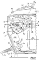
- a pipe cleaning machine 1 is shown, the housing 2 consists of a peripheral frame 3 and two housing covers, not shown, which are screwed onto both sides of the frame 3.
- a flexible cleaning element is guided through the housing 2 along the axis of rotation A-A, which can consist, for example, of the "cleaning spiral" described at the beginning.
- A-A can consist, for example, of the "cleaning spiral” described at the beginning.
- Such a cleaning spiral is shown in EP-A 0 061 003.
- a first hollow shaft 6 is guided concentrically to the axis of rotation AA by means of two roller bearings 4 and 5, on which a toothed belt pulley 7 is arranged in a rotationally fixed manner.
- the toothed belt pulley 7 is connected to a second toothed belt pulley 9 via a toothed belt 8, which sits rotatably on the shaft of a drive motor 10, which is designed as an AC motor with capacitor 11 ( Figure 4).
- the hollow shaft 6 can be set in rotation, which carries at its inner end a driver 12 which is provided with a hollow cone surface (not specified) for receiving a friction clutch 13.
- the friction clutch 13 consists in a known manner of several approximately sector-shaped clutch shoes, which are held in the unloaded state by pressure springs (one of which is shown) at a distance from one another and from the cleaning element.
- a second hollow shaft 16 is mounted in the housing 2 - likewise concentrically to the axis of rotation AA - by means of needle bearings 14 and 15, with the interposition of a longitudinally displaceable bearing bush 17 which has a collar 17a at its inner end.
- a pressure sleeve 18 is fastened in a rotationally fixed manner, which also has a hollow cone surface on its inside. In this way, the friction clutch 13 is held in the manner shown between the two hollow cone surfaces.
- a pressure bearing 19 is arranged between the collar 17a and the pressure sleeve 18, so that the axial movement of the bearing sleeve 17 transmits the displacement movement to the pressure sleeve 18.
- the axial displacement of the pressure sleeve 18 against the axially immovable driver 12, due to the hollow cone surfaces described, causes the individual jaws of the friction clutch 13 to compress radially, and it depends on the actuating force exerted on the pressure sleeve 18 with which radial pressing force the individual jaws of the friction clutch 13 attach the flexible cleaning element is pressed, or with what torque the friction clutch 17 acts on the flexible cleaning element.
- the bearing bush 17 is in turn mounted in a bearing body 20 which is fixed to the housing and has an eye 20a on its underside with a lever axis 21.
- This lever axis runs parallel to a mounting surface 23 and perpendicular to the axis of rotation AA and carries a hand lever 22 which penetrates the frame 3 and has an approximately horizontal handle end 22a at its free end and angled at its inner end with a fork part 24 is, the two legs of which are penetrated by the lever axis 21.
- An elastomeric bellows 25 is provided for sealing between frame 3 and hand lever 22.
- the control panel 26 shown in FIG. 3 is also arranged on the top of the frame 3.
- FIG. 2 the same parts as in FIG. 1 are provided with the same reference symbols.
- a power supply line 27 is used for the power supply, which is introduced into the interior of the housing via an anti-kink sleeve 28 and a stuffing box screw connection 29 and ends there in a terminal box 30 (FIGS. 2 and 4). From this another line 31 leads to the control panel 26, which will be discussed in more detail below.
- a distribution box 32 On the side opposite the terminal box 30 there is a distribution box 32 in which the entire wiring for the electrical control is brought together.
- the line routing is essentially explained with reference to FIG. 4. What is essential here is only the spatial position of the individual switching elements in relation to those components which control these switching elements.
- FIG. 1 shows a first switching element 33 for the drive motor 10.
- This switching element 33 is designed as an inductive proximity switch and responds to the approach or distance of the hand lever 22. More specifically, it is a matter of detecting the position of the fork part 24, which is in the position shown in FIG. 1 in the immediate vicinity of the Switching element 33 is located. If the hand lever 22 is pressed down from this position, the drive motor 10 is first energized so that the hollow shaft 6 is driven. The driver 12, the pressure sleeve 18 and the friction clutch 13 take part in this rotation. With increasing downward movement, the drive motor 10 of course remains switched on, but by reducing the distance between the driver 12 and the pressure sleeve 18, the friction clutch 13 is compressed, the torque transmitted to the flexible cleaning element increasing.
- FIG. 2 first shows how the actuation of the hand lever 22 is transmitted to the friction clutch 13.
- the fork part 24 is connected to the collar 17a above the lever axis 21 via hinge pins 34, rigid tabs 35 and further hinge pins 36, only the front of which are visible.
- the parts 34, 35 and 36 are, however, present in pairs in a mirror-symmetrical arrangement.
- the collar 17a in turn acts on the pressure sleeve 18 via the thrust bearing 19 in the manner already described.
- a second switching element 37 is arranged for reversing the direction of rotation of the drive motor 10. Since the pivoting movement of the fork part 24 is identical to the pivoting movement of the hand lever 22, the hand lever 22 therefore also acts on the second switching element 37.
- This second switching element is designed as a mechanical changeover switch and reacts to the stop of the fork part 24.
- an adjustable stop 38 is assigned to the second switching element 37.
- FIG. 3 also shows that a main switch 43 is arranged in the control panel 26, the actuating element of which is designed as a rocker switch 43a.
- the indicator element 41 or 42 which indicates the starting direction of rotation of the drive motor 10 in which the motor starts when the hand lever 22 is pressed down and thereby actuates the first switching element 33 lights up immediately.
- a control lamp 44 is arranged below the transparent rocker switch 43a, which indicates the operational readiness of the pipe cleaning machine (FIG. 4).
- the lever axis 21 runs parallel to a mounting surface 23 (FIG. 7) and perpendicular to the axis of rotation AA and carries the hand lever 22, which penetrates the frame 3 and has an angled handle end at its free end and a fixed part with a fork part 24 at its inner end is connected, the two legs 24a and 24c of which are penetrated by the lever axis 21. Both legs 24a and 24c are connected to the collar 17a via tabs 35 (FIGS. 5 and 7).
- a power supply line 27 is used for the power supply, which is introduced into the interior of the housing via an anti-kink sleeve 28 and a stuffing box screw connection 29 and ends there in a terminal box 30 (FIG. 7). From this another line 31 leads to the control panel. On the side opposite the terminal box 30 there is an electronic switch box 32a, in which the entire wiring for the electrical control is brought together. What is essential here is only the spatial position of the individual switching elements in relation to those components which control these switching elements.
- FIGS. 5 and 6 show a first switching element 33a for the drive motor 10.
- This switching element 33a is designed as a reed relay and responds to the movement of the hand lever 22. More precisely, it is the detection of the position of a control part 50, which is laterally offset in the position shown in FIG. 5 (see FIG. 6) between the switching element 33a and a further switching element 37a, which is likewise designed as a reed relay.
- the control part 50 is a pin-shaped permanent magnet.
- the control part 50 pivoted upward and the switching element 33a first the drive motor 10 is energized so that the hollow shaft 6 is driven.
- the driver 12, the pressure sleeve 18 and the friction clutch 13 take part in this rotation.
- the drive motor 10 With increasing downward movement, the drive motor 10 of course remains switched on, however, by reducing the distance between the driver 12 and the pressure sleeve 18, the friction clutch 13 is compressed, the torque transmitted to the flexible cleaning element increasing (see again FIG. 1).
- FIGS. 5 and 6 show how the actuation of the hand lever 22 is transmitted to the friction clutch 13.
- the fork part 24 is connected above the lever axis 21 via two hinge pins 34, two rigid tabs 35 and two further hinge pins 36 to the collar 17a, which in turn acts on the pressure sleeve 18 via the thrust bearing 19 in the manner already described. Since the pivoting movement of the fork part 24 is identical to the pivoting movement of the hand lever 22, the hand lever 22 therefore also acts on the second switching element 37a.
- an adjustable stop buffer 38a is assigned to it, which is made of an elastomeric material, e.g. made of rubber ( Figure 7).
- the leg 24a of the fork part 24 facing the viewer in FIG. 5 has at its end below the lever axis 21 a receptacle 24b into which an approximately radially projecting holding part 51 is inserted, which in turn is inserted has at its end a cylindrical arm 52, in the end of which the control part 50 is inserted in the form of a pin-shaped permanent magnet 50a. Because of the arrangement made, the control part 50 pivots about the lever axis 21 and, alternatively, gets into the area of influence of the magnetically actuated switching elements 33a and 37a.
- the Swiveling movements are indicated in FIG. 6 by arrows 53 (switching on, actuating clutch) and 54 (relieving clutch, reversing direction of rotation).
- a tension spring 55 which is stretched between the bearing body 20 and the hinge pin 34, holds the hand lever 22 and thus the control body 50 in the neutral intermediate position shown in FIGS. 5 and 6, in which the other leg 24c on the stop buffer shown in FIG 38a rests, which is adjustably supported by a threaded spindle 38b with lock nut 38c in a tab 20a which is attached to the bearing body 20 in a radially projecting manner.
- FIG. 6 also shows that the switching elements 33a and 37a are arranged on the inner wall surface 32b of a wall 32a of the electronic control box 32, which is made of a plastic.
- the alternative possibility of arranging the switching elements on the outer wall surface 32c is shown in dashed lines.
- the neutral position of the switching element 50 is shown by a dash-dotted line N:
- the switching elements 33a and 37a are equally spaced on both sides of the neutral position.
- a transport aid is associated with the hand lever: This consists of a pawl 56 which can be pivoted about an axis 57 and on whose free end the fork part 24 is supported. As a result, the handle end 22a is held approximately horizontally so that it can serve as a handle. To establish the operational readiness, with the handle end 22a depressed, it is sufficient to press the button 58, as a result of which the pawl 56 is pivoted out of the way of the fork part 24 into the neutral position according to FIG.
Landscapes
- Engineering & Computer Science (AREA)
- Health & Medical Sciences (AREA)
- Life Sciences & Earth Sciences (AREA)
- Hydrology & Water Resources (AREA)
- Public Health (AREA)
- Water Supply & Treatment (AREA)
- Mechanical Engineering (AREA)
- Cleaning In General (AREA)
- Cleaning By Liquid Or Steam (AREA)
Claims (14)
- Procédé d'utilisation pour une machine à nettoyer les tuyaux (1) mue par un moteur d'entraînement (10) et comprenant un embrayage à friction (13) pour l'entraînement d'un élément flexible de nettoyage/dégorgement appelé furet, ainsi qu'un levier à main (22) pour commander l'embrayage à friction, l'agencement étant tel qu'à mesure que la pression exercée par le levier augmente, le couple d'entraînement en rotation appliqué au furet croît, caractérisé en ce qu'un mouvement d'inclinaison du levier à main (22)a) produit d'abord la mise en marche du moteur d'entraînement (10) etb) lors de la poursuite du mouvement du levier (22) au-delà de la position de mise en marche, le couple appliqué par l'embrayage à friction (13) au furet est accru, alors que, par un mouvement du même levier en direction contraire au mouvement de mise en marche,c) le sens de rotation du moteur est inversé.
- Machine à nettoyer les tuyaux (1) pour la mise en oeuvre du procédé d'utilisation selon la revendication 1, comprenant un moteur d'entraînement (10), un embrayage à friction (13) pour l'entraînement d'un élément flexible de nettoyage appelé furet, l'embrayage pouvant être entraîné en rotation par le moteur et commandé par un levier à main (22) inclinable, ainsi que des organes de commutation (33, 33a, 33b et 37, 37a, 37b), pouvant être commandés à partir du levier et servant à la mise en marche et l'arrêt du moteur (10), de même qu'au changement du sens de rotation du moteur, caractérisée en ce que les organes de commutation pour la mise en marche et l'inversion du sens de rotation du moteur d'entraînement (10) sont disposés dans la zone de mouvement du levier à main (22) ou d'au moins une pièce de commande (50) reliée à lui, de manière que par une inclinaison du levier dans une première direction de mouvement, le moteur (10) puisse être mis en marche d'abord et l'embrayage à friction puisse ensuite être commandé en vue de l'application au furet d'un couple d'entraînement en rotation croissant, et qu'une inclinaison du levier dans la direction de mouvement contraire puisse produire l'inversion du sens de rotation du moteur (10).
- Machine à nettoyer les tuyaux selon la revendication 2, caractérisée en ce que le levier (22) est monté sur un axe de levier (21), à l'intérieur d'une carrosserie (2) et au moyen d'une partie de levier en forme de fourche (24) possédant deux branches parallèles (24a, 24b), et que les organes de commutation (33, 33a, 33b et 37, 37a, 37b) peuvent être commandés par le mouvement de la fourche (24) dans le sens de la mise en marche du moteur d'entraînement (10) ou de l'inversion de son sens de rotation.
- Machine à nettoyer les tuyaux selon la revendication 2, caractérisée en ce que des éléments indicateurs (41, 41a; 42, 42a) pour l'indication du sens de rotation sont coordonnés à l'organe de commutation (37, 37a, 37b) pour l'inversion du sens de rotation du moteur d'entraînement (10).
- Machine à nettoyer les tuyaux selon la revendication 2, caractérisée en ce que l'organe de commutation (33) pour la mise en marche et l'arrêt du moteur d'entraînement (10) est un organe de commutation du type à commande de proximité faisant partie du groupe des capteurs capacitifs, inductifs ou optoélectroniques.
- Machine à nettoyer les tuyaux selon la revendication 2, caractérisée en ce que l'organe de commutation (37) pour l'inversion du sens de rotation du moteur d'entraînement (10) est un commutateur bistable de type à contacts.
- Machine à nettoyer les tuyaux selon la revendication 2, caractérisée en ce que la pièce de commande (50) est un aimant (50a), que les organes de commutation (33a, 37a ou 33b, 37b) sont des commutateurs à commande magnétique et que la pièce de commande (50) occupe, à la position de repos du levier (22), une position intermédiaire où elle n'exerce pas d'influence sur les organes de commutation (33a, 37b ou 33b, 37b), mais peut être amenée alternativement dans la zone d'actionnement de l'un (33a, 33b) ou de l'autre organe de commutation (37a, 37b) par le mouvement d'inclinaison du levier (22) dans l'une ou l'autre direction.
- Machine à nettoyer les tuyaux selon la revendication 7, caractérisée en ce que le levier (22) est monté, à l'intérieur d'une carrosserie (2), sur un axe de levier (21) au moyen d'une partie de levier en forme de fourche (24), possédant deux branches parallèles (24a, 24c), et que la pièce de commande (50) est fixée à une branche (24a) de la fourche (24).
- Machine à nettoyer les tuyaux selon la revendication 8, caractérisée en ce qu'une branche (24a) de la fourche (24) est pourvue, au-delà de l'axe de levier (21), d'une pièce de support (51) portant une flèche (52) dans l'extrémité de laquelle est disposée la pièce de commande (50) sous la forme d'un aimant permanent (50a).
- Machine à nettoyer les tuyaux selon la revendication 8, caractérisée en ce que les organes de commutation (33a, 37a ou 33b, 37b) sont réalisés comme des relais à lames vibrantes.
- Machine à nettoyer les tuyaux selon la revendication 8, caractérisée en ce que les organes de commutation (33a, 37a ou 33b, 37b) sont fixés à une paroi (32a) d'un boîtier électronique et de commutation (32) parallèlement à laquelle peut se déplacer la pièce de commande (50).
- Machine à nettoyer les tuyaux selon la revendication 11, caractérisée en ce que le boîtier électronique et de commutation (32) est fait d'un matériau amagnétique et que les organes de commutation (33a, 37a) sont disposés sur une face interne (33b) d'une paroi de ce boîtier.
- Machine à nettoyer les tuyaux selon la revendication 7, caractérisée en ce qu'un tampon de butée (38a) est coordonné à la fourche (24), tampon contre lequel la fourche vient s'appliquer lors du mouvement vers le haut du levier (22).
- Machine à nettoyer les tuyaux selon la revendication 13, caractérisée en ce que le tampon de butée (38a) est disposé réglable dans la direction du mouvement d'inclinaison de la fourche (24).
Applications Claiming Priority (4)
| Application Number | Priority Date | Filing Date | Title |
|---|---|---|---|
| DE4301179 | 1993-01-19 | ||
| DE4301179A DE4301179C2 (de) | 1993-01-19 | 1993-01-19 | Verfahren zum Betrieb einer Rohrreinigungsmaschine und Rohrreinigungsmaschine für die Durchführung des Verfahrens |
| DE4341075 | 1993-12-02 | ||
| DE4341075A DE4341075C2 (de) | 1993-01-19 | 1993-12-02 | Antrieb eines flexiblen Reinigungselements einer Rohrreinigungsmaschine |
Publications (2)
| Publication Number | Publication Date |
|---|---|
| EP0607612A1 EP0607612A1 (fr) | 1994-07-27 |
| EP0607612B1 true EP0607612B1 (fr) | 1997-03-12 |
Family
ID=25922331
Family Applications (1)
| Application Number | Title | Priority Date | Filing Date |
|---|---|---|---|
| EP93120906A Expired - Lifetime EP0607612B1 (fr) | 1993-01-19 | 1993-12-26 | Procédé d'utilisation pour une machine de nettoyage des tuyaux et machine pour la mise en oeuvre ce procédé |
Country Status (3)
| Country | Link |
|---|---|
| EP (1) | EP0607612B1 (fr) |
| AT (1) | ATE149887T1 (fr) |
| DE (3) | DE4301179C2 (fr) |
Cited By (4)
| Publication number | Priority date | Publication date | Assignee | Title |
|---|---|---|---|---|
| DE19841813A1 (de) * | 1998-09-12 | 2000-03-23 | Rothenberger Werkzeuge Ag | Rohrreinigungsmaschine |
| US11396034B2 (en) | 2019-09-30 | 2022-07-26 | Milwaukee Electric Tool Corporation | Motor control of a drain cleaning machine |
| US11999033B2 (en) | 2019-10-03 | 2024-06-04 | Milwaukee Electric Tool Corporation | Drain cleaner cable decoupler tool |
| US12134115B2 (en) | 2020-02-12 | 2024-11-05 | Milwaukee Electric Tool Corporation | Drain cleaning machine |
Families Citing this family (8)
| Publication number | Priority date | Publication date | Assignee | Title |
|---|---|---|---|---|
| DE19739359C2 (de) * | 1997-09-09 | 1999-08-19 | Seitz | Tragbare Rohrreinigungsmaschine |
| US6076219A (en) * | 1999-01-15 | 2000-06-20 | Irwin; Lawrence F. | Waste line clean out apparatus |
| DE102014101010A1 (de) * | 2014-01-28 | 2015-07-30 | Lehmann Gmbh & Co. Kg | Rohr- und Kanalreinigungsmaschine |
| CN218945840U (zh) | 2018-08-10 | 2023-05-02 | 米沃奇电动工具公司 | 排水管清洁组件和引导组件 |
| DE102019130917A1 (de) * | 2019-02-14 | 2020-08-20 | Lehmann Gmbh & Co. Kg | Rohr- und Kanalreinigungsmaschine sowie Verfahren für die Verwendung der Rohr- und Kanalreinigungsmaschine |
| WO2020231966A1 (fr) | 2019-05-15 | 2020-11-19 | Milwaukee Electric Tool Corporation | Dispositif de nettoyage de drains |
| DE102022102628A1 (de) * | 2022-02-03 | 2023-08-03 | Lehmann Gmbh & Co. Kg | Rohr- und Kanalreinigungsmaschine |
| CN114673249B (zh) * | 2022-04-06 | 2023-11-17 | 温州凯睿建设有限公司 | 一种市政下水管道清理装置及其清理方法 |
Family Cites Families (8)
| Publication number | Priority date | Publication date | Assignee | Title |
|---|---|---|---|---|
| US3213473A (en) * | 1963-09-03 | 1965-10-26 | Singer Louis | Pipe cleaning device |
| DE1690197A1 (de) * | 1968-01-17 | 1971-05-06 | Scheer & Cie C F | Magnet-Schwimmerschalter |
| US3776179A (en) * | 1968-09-24 | 1973-12-04 | W Raney | Device for pushing and pulling implements, including cables, into and from conduits and the like |
| DE2613944C3 (de) * | 1976-04-01 | 1981-07-23 | Rowo Rohrwolf Produktions Ag Und Co Vertriebs Kg, 3436 Hessisch Lichtenau | Tragbares Rohrreinigungsgerät mit einer in Umdrehung versetzbaren Drahtwendel |
| DE3109876A1 (de) * | 1981-03-14 | 1982-09-30 | Rothenberger GmbH & Co Werkzeuge-Maschinen KG, 6000 Frankfurt | Rohrreinigungsmaschine mit einem behaelter fuer die aufnahme von reinigungsspiralen unterschiedlicher durchmesser |
| US4361924A (en) * | 1981-06-24 | 1982-12-07 | Lawrence Irwin F | Grip handle chuck |
| CH682061A5 (en) * | 1991-07-12 | 1993-07-15 | Eduard Isenschmid | Flat-work-cutting machine |
| DE9110901U1 (de) * | 1991-09-03 | 1992-01-02 | Horst Klünder GmbH, 6367 Karben | Rohrreinigungsgerät |
-
1993
- 1993-01-19 DE DE4301179A patent/DE4301179C2/de not_active Expired - Fee Related
- 1993-12-02 DE DE4341075A patent/DE4341075C2/de not_active Expired - Fee Related
- 1993-12-26 AT AT93120906T patent/ATE149887T1/de active
- 1993-12-26 DE DE59305768T patent/DE59305768D1/de not_active Expired - Fee Related
- 1993-12-26 EP EP93120906A patent/EP0607612B1/fr not_active Expired - Lifetime
Cited By (6)
| Publication number | Priority date | Publication date | Assignee | Title |
|---|---|---|---|---|
| DE19841813A1 (de) * | 1998-09-12 | 2000-03-23 | Rothenberger Werkzeuge Ag | Rohrreinigungsmaschine |
| DE19841813C2 (de) * | 1998-09-12 | 2001-03-22 | Rothenberger Werkzeuge Ag | Rohrreinigungsmaschine |
| US11396034B2 (en) | 2019-09-30 | 2022-07-26 | Milwaukee Electric Tool Corporation | Motor control of a drain cleaning machine |
| US11638940B2 (en) | 2019-09-30 | 2023-05-02 | Milwaukee Electric Tool Corporation | Motor control of a drain cleaning machine |
| US11999033B2 (en) | 2019-10-03 | 2024-06-04 | Milwaukee Electric Tool Corporation | Drain cleaner cable decoupler tool |
| US12134115B2 (en) | 2020-02-12 | 2024-11-05 | Milwaukee Electric Tool Corporation | Drain cleaning machine |
Also Published As
| Publication number | Publication date |
|---|---|
| DE4301179A1 (de) | 1994-07-21 |
| DE59305768D1 (de) | 1997-04-17 |
| DE4341075A1 (de) | 1995-06-08 |
| DE4301179C2 (de) | 1995-11-16 |
| EP0607612A1 (fr) | 1994-07-27 |
| DE4341075C2 (de) | 1996-06-05 |
| ATE149887T1 (de) | 1997-03-15 |
Similar Documents
| Publication | Publication Date | Title |
|---|---|---|
| EP0607612B1 (fr) | Procédé d'utilisation pour une machine de nettoyage des tuyaux et machine pour la mise en oeuvre ce procédé | |
| DE3543143C2 (de) | Werkzeugmaschine mit elektromagnetischer Grundplatte | |
| DE69412957T2 (de) | Linearer Antrieb | |
| EP0182986B1 (fr) | Dispositif de serrage actionné par moteur avec réglage du couple variable | |
| DE3009516C2 (de) | Bohrmaschine mit magnetischer basis | |
| DE69734079T2 (de) | Elektricher Stellantrieb | |
| DE68907376T2 (de) | Elektrische Zange mit magnetischer Halterung. | |
| DE102011014543A1 (de) | Medizinisches Instrument | |
| EP1420974B1 (fr) | Levier de retrogradage force resistant a l'usure | |
| EP0239670B1 (fr) | Machine motorisée avec réglage du couple, en particulier outillages électriques | |
| DE3039584C2 (de) | Regulierhebel, insbesondere zur Vorwahl der Fahrgeschwindigkeit an selbstfahrenden landwirtschaftlichen Maschinen | |
| DE2613944C3 (de) | Tragbares Rohrreinigungsgerät mit einer in Umdrehung versetzbaren Drahtwendel | |
| DE102018130565A1 (de) | 4-Wege-Crimpwerkzeug | |
| EP3643458A2 (fr) | Dispositif de préhension permettant d'appréhender des feuilles métalliques | |
| DE102004008488A1 (de) | Intelligenter Schalter | |
| EP1201800B1 (fr) | Entraínement rotatif pour un rotor de filage pendant son nettoyage | |
| DE3025974A1 (de) | Antriebsvorrichtung fuer einen schlitten | |
| DE10045116A1 (de) | Medizinisches oder dentalmedizinisches Handstück | |
| DE602005002217T2 (de) | Werkzeugschadenerfassungseinrichtung | |
| EP0038287B1 (fr) | Poignée rotative pour commande à la main d'une propulsion d'énergie | |
| DE10016290A1 (de) | Küchenmaschine | |
| DE7908672U1 (de) | Vorrichtung zur Bearbeitung zahnärztlicher Werkstücke | |
| DE1550964A1 (de) | Steuervorrichtung fuer Antriebe | |
| DE202007018780U1 (de) | Sicherheitsmechanismus für eine Küchenmaschine mit Rührschüssel und Deckel | |
| EP2712996A2 (fr) | Dispositif de mouvement pour un élément mobile de meuble |
Legal Events
| Date | Code | Title | Description |
|---|---|---|---|
| PUAI | Public reference made under article 153(3) epc to a published international application that has entered the european phase |
Free format text: ORIGINAL CODE: 0009012 |
|
| AK | Designated contracting states |
Kind code of ref document: A1 Designated state(s): AT BE CH DE DK FR GB IT LI LU NL SE |
|
| 17P | Request for examination filed |
Effective date: 19950119 |
|
| 17Q | First examination report despatched |
Effective date: 19951116 |
|
| GRAG | Despatch of communication of intention to grant |
Free format text: ORIGINAL CODE: EPIDOS AGRA |
|
| GRAH | Despatch of communication of intention to grant a patent |
Free format text: ORIGINAL CODE: EPIDOS IGRA |
|
| GRAH | Despatch of communication of intention to grant a patent |
Free format text: ORIGINAL CODE: EPIDOS IGRA |
|
| GRAA | (expected) grant |
Free format text: ORIGINAL CODE: 0009210 |
|
| ITF | It: translation for a ep patent filed | ||
| AK | Designated contracting states |
Kind code of ref document: B1 Designated state(s): AT BE CH DE DK FR GB IT LI LU NL SE |
|
| PG25 | Lapsed in a contracting state [announced via postgrant information from national office to epo] |
Ref country code: DK Effective date: 19970312 |
|
| REF | Corresponds to: |
Ref document number: 149887 Country of ref document: AT Date of ref document: 19970315 Kind code of ref document: T |
|
| REG | Reference to a national code |
Ref country code: CH Ref legal event code: EP |
|
| REG | Reference to a national code |
Ref country code: CH Ref legal event code: NV Representative=s name: KEMENY AG PATENTANWALTBUERO |
|
| GBT | Gb: translation of ep patent filed (gb section 77(6)(a)/1977) |
Effective date: 19970313 |
|
| RAP2 | Party data changed (patent owner data changed or rights of a patent transferred) |
Owner name: ROTHENBERGER WERKZEUGE AKTIENGESELLSCHAFT |
|
| REF | Corresponds to: |
Ref document number: 59305768 Country of ref document: DE Date of ref document: 19970417 |
|
| NLT2 | Nl: modifications (of names), taken from the european patent patent bulletin |
Owner name: ROTHENBERGER WERKZEUGE AKTIENGESELLSCHAFT |
|
| PG25 | Lapsed in a contracting state [announced via postgrant information from national office to epo] |
Ref country code: SE Effective date: 19970612 |
|
| ET | Fr: translation filed | ||
| PLBE | No opposition filed within time limit |
Free format text: ORIGINAL CODE: 0009261 |
|
| STAA | Information on the status of an ep patent application or granted ep patent |
Free format text: STATUS: NO OPPOSITION FILED WITHIN TIME LIMIT |
|
| PGFP | Annual fee paid to national office [announced via postgrant information from national office to epo] |
Ref country code: LU Payment date: 19980205 Year of fee payment: 5 |
|
| PGFP | Annual fee paid to national office [announced via postgrant information from national office to epo] |
Ref country code: CH Payment date: 19980210 Year of fee payment: 5 |
|
| 26N | No opposition filed | ||
| PGFP | Annual fee paid to national office [announced via postgrant information from national office to epo] |
Ref country code: GB Payment date: 19981223 Year of fee payment: 6 |
|
| PGFP | Annual fee paid to national office [announced via postgrant information from national office to epo] |
Ref country code: FR Payment date: 19981224 Year of fee payment: 6 Ref country code: BE Payment date: 19981224 Year of fee payment: 6 |
|
| PG25 | Lapsed in a contracting state [announced via postgrant information from national office to epo] |
Ref country code: LU Free format text: LAPSE BECAUSE OF NON-PAYMENT OF DUE FEES Effective date: 19981226 |
|
| PGFP | Annual fee paid to national office [announced via postgrant information from national office to epo] |
Ref country code: AT Payment date: 19981228 Year of fee payment: 6 |
|
| PG25 | Lapsed in a contracting state [announced via postgrant information from national office to epo] |
Ref country code: LI Free format text: LAPSE BECAUSE OF NON-PAYMENT OF DUE FEES Effective date: 19981231 Ref country code: CH Free format text: LAPSE BECAUSE OF NON-PAYMENT OF DUE FEES Effective date: 19981231 |
|
| PGFP | Annual fee paid to national office [announced via postgrant information from national office to epo] |
Ref country code: NL Payment date: 19981231 Year of fee payment: 6 |
|
| PGFP | Annual fee paid to national office [announced via postgrant information from national office to epo] |
Ref country code: DE Payment date: 19990301 Year of fee payment: 6 |
|
| REG | Reference to a national code |
Ref country code: CH Ref legal event code: PL |
|
| PG25 | Lapsed in a contracting state [announced via postgrant information from national office to epo] |
Ref country code: GB Free format text: LAPSE BECAUSE OF NON-PAYMENT OF DUE FEES Effective date: 19991226 Ref country code: AT Free format text: LAPSE BECAUSE OF NON-PAYMENT OF DUE FEES Effective date: 19991226 |
|
| PG25 | Lapsed in a contracting state [announced via postgrant information from national office to epo] |
Ref country code: BE Free format text: LAPSE BECAUSE OF NON-PAYMENT OF DUE FEES Effective date: 19991231 |
|
| BERE | Be: lapsed |
Owner name: ROTHENBERGER WERKZEUGE A.G. Effective date: 19991231 |
|
| PG25 | Lapsed in a contracting state [announced via postgrant information from national office to epo] |
Ref country code: NL Free format text: LAPSE BECAUSE OF NON-PAYMENT OF DUE FEES Effective date: 20000701 |
|
| GBPC | Gb: european patent ceased through non-payment of renewal fee |
Effective date: 19991226 |
|
| PG25 | Lapsed in a contracting state [announced via postgrant information from national office to epo] |
Ref country code: FR Free format text: LAPSE BECAUSE OF NON-PAYMENT OF DUE FEES Effective date: 20000831 |
|
| NLV4 | Nl: lapsed or anulled due to non-payment of the annual fee |
Effective date: 20000701 |
|
| PG25 | Lapsed in a contracting state [announced via postgrant information from national office to epo] |
Ref country code: DE Free format text: LAPSE BECAUSE OF NON-PAYMENT OF DUE FEES Effective date: 20001003 |
|
| REG | Reference to a national code |
Ref country code: FR Ref legal event code: ST |
|
| PG25 | Lapsed in a contracting state [announced via postgrant information from national office to epo] |
Ref country code: IT Free format text: LAPSE BECAUSE OF NON-PAYMENT OF DUE FEES;WARNING: LAPSES OF ITALIAN PATENTS WITH EFFECTIVE DATE BEFORE 2007 MAY HAVE OCCURRED AT ANY TIME BEFORE 2007. THE CORRECT EFFECTIVE DATE MAY BE DIFFERENT FROM THE ONE RECORDED. Effective date: 20051226 |