EP0607638B1 - Système de télémétric pour dispositif cardiaque implantable - Google Patents
Système de télémétric pour dispositif cardiaque implantable Download PDFInfo
- Publication number
- EP0607638B1 EP0607638B1 EP93250362A EP93250362A EP0607638B1 EP 0607638 B1 EP0607638 B1 EP 0607638B1 EP 93250362 A EP93250362 A EP 93250362A EP 93250362 A EP93250362 A EP 93250362A EP 0607638 B1 EP0607638 B1 EP 0607638B1
- Authority
- EP
- European Patent Office
- Prior art keywords
- command
- transmitter
- receiver
- programmer
- implantable
- Prior art date
- Legal status (The legal status is an assumption and is not a legal conclusion. Google has not performed a legal analysis and makes no representation as to the accuracy of the status listed.)
- Expired - Lifetime
Links
Images


Classifications
-
- A—HUMAN NECESSITIES
- A61—MEDICAL OR VETERINARY SCIENCE; HYGIENE
- A61N—ELECTROTHERAPY; MAGNETOTHERAPY; RADIATION THERAPY; ULTRASOUND THERAPY
- A61N1/00—Electrotherapy; Circuits therefor
- A61N1/18—Applying electric currents by contact electrodes
- A61N1/32—Applying electric currents by contact electrodes alternating or intermittent currents
- A61N1/36—Applying electric currents by contact electrodes alternating or intermittent currents for stimulation
- A61N1/372—Arrangements in connection with the implantation of stimulators
- A61N1/37211—Means for communicating with stimulators
- A61N1/37252—Details of algorithms or data aspects of communication system, e.g. handshaking, transmitting specific data or segmenting data
- A61N1/37276—Details of algorithms or data aspects of communication system, e.g. handshaking, transmitting specific data or segmenting data characterised by means for reducing power consumption during telemetry
-
- A—HUMAN NECESSITIES
- A61—MEDICAL OR VETERINARY SCIENCE; HYGIENE
- A61N—ELECTROTHERAPY; MAGNETOTHERAPY; RADIATION THERAPY; ULTRASOUND THERAPY
- A61N1/00—Electrotherapy; Circuits therefor
- A61N1/18—Applying electric currents by contact electrodes
- A61N1/32—Applying electric currents by contact electrodes alternating or intermittent currents
- A61N1/36—Applying electric currents by contact electrodes alternating or intermittent currents for stimulation
- A61N1/372—Arrangements in connection with the implantation of stimulators
- A61N1/37211—Means for communicating with stimulators
- A61N1/37252—Details of algorithms or data aspects of communication system, e.g. handshaking, transmitting specific data or segmenting data
- A61N1/37254—Pacemaker or defibrillator security, e.g. to prevent or inhibit programming alterations by hackers or unauthorised individuals
Definitions
- the present invention generally relates to a telemetry system for an implantable cardiac device.
- the present invention is more particularly directed to a telemetry system for an implantable cardiac device which monitors activity of a human heart, which also may additionally deliver therapy to the human heart, and which communicates with a non-implanted external device.
- the present invention is more particularly directed to a cardiac device which utilizes such a system to provide reduced power consumption while communicating data and command transmissions at a high transmission rate and with error correction and detection to assure accurate transmission even in noisy environments.
- Implantable cardiac devices are designed to be small in size and implanted beneath the skin of a patient. Such devices establish electrical contact with the heart by one or more electrical leads having electrodes implanted within the heart, attached to the surface of the heart, or disposed subcutaneously and spaced from the heart.
- Implantable cardiac devices include devices which monitor heart activity. Monitoring heart activity includes sensing electrical signals generated by the heart, recording data indicative of the sensed electrical signals and analyzing the recorded data to provide characterization data of the heart activity. Such devices detect arrhythmias of the heart, ischemia, or other conditions. The implantable device, under direction of a microprocessor, generates data indicative of these conditions and stores the data in memory. The data may be retrieved by an external device through telemetry.
- cardiac devices may also provide corrective therapy to the heart in the form of applied electrical energy.
- One such cardiac device is an implantable atrial defibrillator. Atrial defibrillators function to sense heart activity and deliver cardioverting or defibrillating electrical energy to the atria of the heart when the atria are in need of cardioversion. Control of these devices is provided by internal circuits including devices such as a microprocessor. The microprocessor may be coupled to a sensing circuit which senses the electrical activity of the heart and produce digital data corresponding to the sensed electrical activity. An atrial defibrillator implemented in the microprocessor in turn analyzes the digital data to detect conditions such as fibrillation of the atria. In response to detecting such a condition, the microprocessor directs other circuitry to apply defibrillating electrical energy to the atria of the heart to defibrillate the atria and return the heart to a normal rhythm.
- Implanted cardiac devices such as these may receive command instructions from a non-implanted device such as a programmer which is external to the skin of the patient. These command instructions are referred to herein as inbound transmissions, viewed from the perspective of the implanted device.
- the received command instructions may include program instructions or steps for directing the microprocessor's operation.
- the received command instructions may also include data such as program limits and timing data.
- the implantable cardiac device may transmit ECG or characterization data and other information to the external device. These are referred to herein as outbound transmissions, viewed from the perspective of the implanted device.
- the programmer may function to receive information from the implanted device as well as to transmit command transmissions including programming commands to the implanted device. Communication between the implanted device and the programmer may be limited to transmissions by only one of the devices with the other device receiving those transmissions. Alternatively, communication between the implanted device and the programmer may include transmissions by both devices.
- Such communication is facilitated by receiving and transmitting circuits included in the implantable cardiac device and in the programmer.
- the receiving and transmitting circuits may cooperate with the microprocessor to receive command transmissions from the programmer and to transmit data and other information to the programmer.
- the programmer includes analogous transmitting and receiving circuits for communicating with the implanted cardiac device. Both the implanted cardiac device and the programmer include an antenna or antennas coupled to the receiving and transmitting means for transmitting and receiving electromagnetic energy.
- Prior art devices typically enclose the antenna or antennas of the implanted cardiac device inside the enclosure of the implanted device.
- Such enclosures are typically metallic in nature and may be made of titanium.
- Metal enclosures act as low pass filters to limit the bandwidth of signals transmitted from and received by the implanted cardiac devices.
- Prior art designs which enclosed the antenna or antennas in the enclosure have experienced limited data transmission rates of less than 10 K bits/second.
- Both the receiving circuit and the transmitting circuit of an implanted cardiac device are used only intermittently to communicate with the programmer. After command transmissions are received from the programmer or after data and other information is transmitted to the programmer, the receiving means and transmitting means may remain inactive for extended periods of time. Accordingly, these circuits are well-suited to being de-energized when not in use in order to minimize power consumption.
- One possible design for activating the device is passive wakeup.
- the programmer transmits a wakeup command with sufficient energy to convert the receiving means of the implanted device from a quiescent state, in which receiving and transmitting circuits are de-energized, to an active state, in which the implanted device and programmer are communicating.
- a relatively large receiving antenna is required in order to couple sufficient electromagnetic energy to the receiving means to facilitate this wakeup function.
- Such an antenna may be inconsistent with a physically compact implanted cardiac device or with an implanted cardiac device with the antenna in the header.
- the header is the epoxy or other non-metallic cover which sealingly engages the metallic enclosure of the implantable cardiac device.
- the antenna may be large enough that a wakeup command can be received by a quiescent circuit.
- the need for an active circuit to receive the wakeup command becomes apparent. Therefore, there is a need for an implanted device having a receiving circuit which may rest in a quiescent state and requires only a single, relatively small antenna while still providing reduced power consumption.
- a further aspect of assuring accuracy of transmitted data is establishing a reliable data link.
- programmer antennas are disposed in moveable programmer heads which are to be placed in close proximity to the implantation site of the cardiac device. Because the implanted cardiac device is implanted and not visible, determining the proper orientation of the programming head of the external device can be difficult. To assure that data is transmitted accurately, the programming head antennas must be positioned to maximize signal strength received from the implanted cardiac device. Accordingly, there is a need for a telemetry system which provides an indication to the user of the relative received signal strength so that the antennas of the programming head can be positioned properly.
- implantable cardiac devices In addition to assuring reliable communication of command transmissions and response information, another important design criterion for implantable cardiac devices is the ability to avoid locked-up devices after final manufacture of the device.
- a telemetry system including a hardware reset operation which will reset the cardiac device to a predetermined initial state. For this operation to function properly, the receiving means and transmitting means of the cardiac device must be able to operate independently of the microprocessor.
- US-A-4,979,506 discloses a cardiac device which monitors activity of a human heart, or provides therapy to the human heart, or both.
- the cardiac device is implantable beneath the skin of a patient and communicates with a non-implanted external receiver and transmitter.
- the receiver receives command transmissions from the non-implanted external transmitter, wherein the command transmissions conform to a first protocol.
- the transmitter is for transmitting information including the data to the non-implanted external receiver.
- this prior art cardiac device uses the same protocols for inbound (to implanted device) and outbound (from an implanted device) and information transmissions respectively.
- US-A-4,944,299 discloses different types of telemetry schemes or transmission principles are typically used to transfer data from the implanted device to the external device than are used to transfer data from the external device to the implanted device.
- the different types of "transmission principles" being referred to are different transmission techniques, such as static magnetic field coupling, reflected impedance coupling, and RF coupling.
- US-A-4,681,111 suggests transmitting energy or data inbound at one frequency while transmitting data outbound at another frequency.
- EP-A-0 362 611 describes transmitters and receivers in one or more implantable and non-implantable devices which communicate with each other at a frequency in the range of 10kH to 100kH by propagating communication signals between the devices in the ion medium of the intra- and extra-cellular body liquids of a patient in which the implantable devices are implanted or to which the external devices are connected.
- Nothing in this reference describes or suggests an implantable device receiving inbound command transmissions in accordance with a first protocol and transmitting outbound data transmissions in accordance with a second, and different, protocol.
- the present invention relates to a system as claimed in claim 1 and to a method as claimed in claim 13.
- FIG. 1 shows a schematic block diagram of a cardiac system 10 embodying the present invention.
- the cardiac system 10 generally includes an implantable cardiac device 12 and an external programmer 14.
- the cardiac device 12 may be implanted beneath the skin of a patient and includes at least one and preferably a plurality of electrodes 16 carried by leads 18 and adapted to make electrical contact with the heart.
- the leads 18 are coupled to a circuit means 20.
- the circuit means 20 may take the form of a defibrillator, pacemaker or monitor circuit of the type known in the art and capable of monitoring activity of the heart of a patient.
- the circuit means 20 takes the form of a defibrillator, it functions to sense heart activity and deliver defibrillating electrical energy to the heart through the electrodes 16 when the heart is in fibrillation.
- the circuit means 20 may take the form of an atrial defibrillator as disclosed, for example, in copending EP-A-0 533 917.
- the circuit means 20 When the circuit means 20 takes the form of a monitor, it detects signals indicative of the functioning of the heart through electrodes 16, converts those signals to digital data and stores the data in memory means 24. More specifically, the circuit means may take the form of a patient monitor as disclosed, for example, in copending US-A-5,313,953.
- the circuit means 20 includes sensing means 19, a direct memory access (“DMA") controller 21, a microprocessor 22, a memory means 24 and a telemetry support section 30.
- the sensing means 19 produces digital data corresponding to electrical activity of the heart sensed by the electrodes 16.
- the memory means 24 stores both command instructions for directing the operation of the microprocessor 22 as well as data indicative of heart activity.
- the cardiac device also includes a depletable energy source such as a battery 26 which supplies electrical energy to the cardiac device 12.
- the cardiac device 12 further includes telemetry means 28.
- the telemetry means 28 is coupled to the microprocessor 22 through a telemetry support section 30.
- the telemetry means 28 has a receiving means such as receiver section 32 and a transmitting means such as transmitter section 34. Both the receiver section 32 and the transmitter section 34 are coupled to the antenna 36 for communicating with the external programmer 14.
- the external programmer 14 includes a receive coil 38 and a transmit coil 40 in a movable wand or programmer head 42.
- the particular programmer head 42 described herein does not form part of the invention, but represents background art useful for understanding the invention.
- the programmer head 42 is placed near the chest of the patient in the vicinity of the implanted cardiac device 12 to allow command instructions to be transmitted to the cardiac device 12 and information to be transmitted to the programmer head 42.
- the programmer head 42 includes external receiving means such as programmer receiver section 44 coupled to the receive coil 38 for decoding information received by the receive coil 38 from the cardiac device 12.
- the programmer head 42 also includes external transmitting means such as programmer transmitter section 46 for encoding command instructions to be transmitted by the transmit coil 40 to the cardiac device 12.
- the programmer head 42 is coupled to a programmer interface 48.
- the programmer interface 48 allows human interface with the cardiac device 12.
- the programmer interface 48 may include devices for displaying information indicative of heart activity collected by the implantable cardiac device 12.
- Programmer interface 48 may also include devices for generating command transmissions to be transmitted to the cardiac device 12.
- programmer interface 48 may allow coupling to telephonic devices to permit transfer of command transmissions to the cardiac device 12 and information from the cardiac device 12 over, for example, telephone lines or cellular telephone links between the patient's location and equipment located, for example, in a doctor's office or hospital.
- the programmer interface 48 sends a command transmission to the cardiac device 12.
- the command transmission is in the form of digital data.
- the data are encoded for transmission by the programmer transmitter section 46 which drives the transmit coil 40.
- Electromagnetic energy is coupled between the transmit coil 40 and the antenna 36 in the cardiac device.
- the receiver section 32 of the telemetry means 28 of the cardiac device 12 senses the energy received by the antenna 36 and decodes the signal to digital data.
- the digital data form a command instruction which is then conveyed to the telemetry support section 30 and the microprocessor 22.
- the microprocessor 22 acts on the received command instruction, for example, by programming an atrial defibrillator.
- the microprocessor 22 analyzes digital data produced by the sensing means 19 and stored in the memory means 24 to detect conditions such as fibrillation of the atria. In response to detecting such a condition, the microprocessor causes defibrillating electrical energy to be applied to the atria of the heart through the leads 18 to defibrillate the atria and return the heart to a normal rhythm.
- the received command may direct the microprocessor 22 to transfer information including data from the memory means 24 to the external programmer 14.
- the received command may implement direct memory access (DMA), bypassing the microprocessor 22 and conveying data from the memory means 24 to the telemetry means 28 under control of DMA controller 21.
- DMA direct memory access
- the information is transferred to the transmitter section 34 of the telemetry means 28.
- the transmitter section 34 encodes the data for transmission and drives the antenna 36. Electromagnetic energy is coupled between the antenna 36 and the receive coil 38 of the programmer head.
- the DMA channel may also be used in the inbound direction to communicate commands from the programmer 14 to the memory means 24 of the implanted cardiac device 12.
- the microprocessor 22 is bypassed and commands transmitted from the programmer 14 are received by the implant receiver section 32 and telemetry support section 30 and then are conveyed via the DMA controller 21 to the memory means 24.
- the programmer receiver section 44 senses the energy received by the receive coil 38 and decodes the signal to digital data. The digital data are then conveyed to the programmer interface 48 for display or further processing.
- the telemetry means 28 thus communicates information from the cardiac device 12 to the external programmer 14 in response to a command transmission communicated from the external programmer 14 to the cardiac device 12.
- One particular command transmission employed, in accordance with the present invention is a command transmission which initiates a communications transaction between the external programmer 14 and the cardiac device 12. This is referred to herein as the initiation command.
- the term “wakeup” is meant to denote the full activation of the telemetry means 28 of the cardiac device 12 in response to an initialization command signal from the external programmer 14.
- the initiation command is transmitted by the external programmer 14 to convert the telemetry means 28 of the cardiac device 12 from a partially active state to a fully active state.
- the receiver section 32 and transmitter section 34 of the telemetry means 28 are generally de-energized.
- the telemetry means 28 enters the partially active state wherein the receiver section 32 is energized to detect energy transmitted by the programmer transmitter section 46. If energy is detected, the receiver section remains energized to look for the transmitted initiation command. If the initiation command is detected, the telemetry means 28 is fully activated and the transmitter section 34 responds by transmitting a response code to the external programmer 14.
- a communications transaction then begins between the external programmer 14 and the cardiac device 12.
- the transmission of command transmissions from the external programmer 14 to the cardiac device 12 is preferably in accordance with a first protocol.
- the transmission of information from the cardiac device 12 to the external programmer 14 is preferably in accordance with a second protocol.
- Figure 2 is a series of diagrams illustrating the first and second transmission protocols which provide for verifying accurate reception of data in accordance with the present invention.
- phase modulation data are encoded through phase modulation.
- a carrier signal phase shift may be modulated in accordance with the transmitted data.
- a single bit of data is encoded per cycle of the carrier.
- Such encoding permits high data transfer rates in accordance with a carrier frequency of 4 Mbits per second.
- the programmer receiver section 44 in the programmer head 42 detects the phase and phase changes of the carrier signal and reproduces the transmitted information and a clock signal.
- both inbound and outbound transmissions include a packet of data.
- the packet in turn comprises one or more frames.
- the frames are used for verifying accurate transmission and receipt of communicated data.
- the telemetry link is reversed and a packet is transmitted in the opposite direction.
- the maximum number of frames in a packet is determined so that transmission time in any one direction is below an upper bound. Very large blocks of data are sent as multiple packets.
- Figure 2(a) shows an outbound packet 50 of data.
- the packet includes a carrier and clock recovery pattern (“CCRP") 52 and one or more outbound frames 54 separated by clock recovery patterns (“CRP”) 56.
- CCRP 52 and the CRP 56 are predetermined patterns of data which allow the programmer receiver section 44 of the programmer head 42 to lock on to the received signal before the programmer receiver section 44 begins receiving frames of data.
- the length of the outbound frames 54 is fixed.
- a fixed frame length provides advantages such as simplified error detection and recovery. While a fixed frame length creates the possibility of wasted time and energy for transmission of small blocks of data that do not fill up a frame, this is outweighed by the noted advantages.
- Figure 2(b) shows an outbound frame 54 of data.
- the outbound frame 54 includes a preamble 58, a frame count 60, a data field 62, a control byte 64, a frame check 66, and a postamble 68.
- the preamble 58 is used to determine the start of every outbound frame 54 of an outbound packet following a CCRP 52 or a CRP 56. If the communications channel was noise free, no further preamble or postamble would be necessary. Since the frames are of fixed length, parsing a frame would require only counting received bits. However, the channel may not be noise free.
- the preamble 58 and postamble 68 are thus used for error detection and recovery in the event of a noisy channel. For a received frame to be considered error-free, the preamble 58, the postamble 68 and the frame check 66 must match the values expected for each of them by the external programmer 14.
- the programmer receiver section 44 in the programmer head 42 counts received bits to determine the position of the fields shown in Figure 2(b). If bits are missed or inserted due to noise, then the preamble or postamble, which comprise predetermined bit patterns, will be in the wrong place and a framing error will be detected. Following a framing error, the external programmer 14 attempts to recover framing by looking for the next preamble.
- the frame count 60 is a sequence number given to each frame.
- the first frame transmitted has a frame count 60 equal to the total number of frames to be transmitted minus one.
- the frame count 60 of each subsequent frame is decremented by one.
- each transmitted frame has a unique frame count identifier.
- the external programmer 14 uses the frame count 60 for recovery of outbound transmissions.
- the final frame sent has a frame count 60 of zero, which value may be used to determine that it is the final frame.
- the control byte 64 may be used to indicate the last frame in the packet 50.
- the control byte 64 preferably echoes the command that invoked the outbound transmission.
- the frame check 66 comprises a block type error detecting code such as cyclic redundancy check code CRC-16, well known in the art.
- the data field 62 may contain various kinds and amounts of information, depending on the command that invoked the outbound transmission. This information may be the data indicative of monitored heart activity produced by the sensing means 19 and stored in the memory means 24 for transmission to the external programmer 14.
- command transmissions which are transmitted from the programmer head 42 to the implantable cardiac device 12
- command transmissions are transmitted according to a first, or inbound, protocol.
- data to be transmitted from the programmer head 42 pulse width modulates a carrier signal by turning on and off the signal. For example, a logical 1 may be transmitted by turning on the carrier signal for one-third of the bit period. A logical 0 may be transmitted by turning on the carrier signal for two-thirds of the bit period. In this manner, the carrier is modulated in accordance with the data to be transmitted.
- inbound transmissions occur at two different speeds.
- commands are transmitted at a first, relatively low, data rate, such as 2,048 bits per second. Because power consumption is proportional to clock rate, a low data rate during this initiation procedure saves power in the cardiac device 12.
- a second, relatively high data rate such as 131,072 bits per second.
- the ability to transmit and receive at multiple speeds also allows both the external programmer 14 and the cardiac device 12 to be adapted to communicate with other devices. In accordance with the first protocol, then, inbound transmissions are at one of two possible rates.
- Figure 2(c) shows a low-speed inbound frame 84 in accordance with the first protocol.
- a leading flag 74 and a trailing flag 82 aid in delimiting the frame.
- a control byte 76 contains the command (such as the aforementioned initiation command) being transmitted to the cardiac device 12.
- the frame check 80 is a block type error detecting code such as CRC-16, well known in the art.
- Figure 2(d) shows an inbound packet 70, in accordance with the first protocol.
- the inbound packet 70 includes one or more inbound frames 72.
- Figure 2(e) shows a high-speed inbound frame 72.
- the high-speed inbound frame 72 includes a leading flag 74, a control byte 76, a data field 78, a frame check 80 and a trailing flag 82.
- the data field 78 may contain various kinds and amounts of data depending on the command.
- the control byte 76 is used to indicate the last frame in the packet 70.
- FIG 3 it illustrates in schematic block diagram form an implantable cardiac device 12 embodying the present, invention capable of communicating with a non-implanted external receiver and transmitter in accordance with the present invention.
- Cardiac device 12 includes the telemetry means 28 and the circuit means 20 which includes telemetry support 30.
- the cardiac device 12 is capable of being fully implanted beneath the skin of a patient for monitoring activity of the heart of the patient and/or providing therapy to the heart.
- the telemetry means 28 includes the receiver section 32; a transmitter section 34, a wakeup detect 35 and an antenna 36.
- the receiver section 32 is coupled to the antenna 36.
- the antenna 36 is preferably located in the neck of the metal enclosure (not shown) which contains cardiac device 12, as disclosed, for example, in the aforementioned US-A-5,313,953. By placing antenna 36 outside the metal enclosure, the metal enclosure will not act as a low pass filter to limit the bandwidth of the signals transmitted and received by the antenna 36. Rather, signals may be transmitted and received at high carrier frequencies such as, for example, 8 MHz.
- the receiver section 32 includes a receive amplifier 86 coupled to the antenna 36.
- the receive amplifier 86 has an enable input 87.
- the receive amplifier 86 is coupled to a pulse counter 88 which has a clear input 90.
- the pulse counter 88 is coupled by data bus 92 to the bit decoder 94.
- the bit decoder 94 decodes incoming data bits in response to a pulse count received from the pulse counter 88 over data bus 92.
- the bit decoder 94 has a bit clock output 96 and a data bit output 98.
- the bit decoder 94 supplies decoded bits of received data to a command decoder 100 over these two outputs.
- the bit decoder 94 also has a clear output 99. Clear output 99 is coupled to the clear input 90 of the pulse counter 88 by the clear line 95 and an OR gate 89. The other input of the OR gate 89 is coupled by enable line 91 to wakeup detect 35 which can independently clear the pulse counter 88.
- the command decoder 100 has a wakeup input 102.
- the command decoder 100 is coupled to telemetry support 30 of the circuit means 20 through read control byte input 104, interrupt output 106, valid command output 108, reset output 110, command data bus 112, DMA write output 114, and DMA acknowledge input 116.
- the receive amplifier 86 when enabled at its enable input 87, detects electromagnetic energy received by the antenna 36 and converts that energy into digital pulses for use by the pulse counter 88.
- the pulse counter 88 counts the number of inbound carrier pulses it receives and produces a pulse count on the data bus 92.
- the data bus 92 supplies to the bit decoder 94 the number of pulses counted by the pulse counter 88.
- the bit decoder 94 preferably samples the 9-bit output data bus 92 at a frequency sixteen times the bit rate.
- the bit decoder 94 is responsive to clocking signals on 16X Clock line 118, which is coupled to bit decoder 30 through an AND gate 120.
- the other input to the AND gate 120 is coupled to the on or enable line 122.
- the on line 122 is coupled to wakeup detect 35 and enable input 87 of receive amplifier 86. Signals on line 122 enable both the receive amplifier 87 and gate the clock signal on the 16X clock line 118.
- the clock signal on 16X Clock line 118 is selected by multiplexer 124 from either the clock signal on 32 KHz clock line 126 or the clock signal on 2 MHz clock line 128 supplied by the telemetry support 30 of the circuit means 20.
- the bit decoder 94 can accurately decode inbound bits at both data rates according to the first protocol.
- the bit decoder 94 uses the number of pulses counted to determine the start of a received bit, the end of a received bit, and the logical value of the received bit. If the number of carrier pulses counted by the pulse counter 88 is greater than a predetermined number, the bit is decoded to be, for example, a logical 0. If the number of carrier pulses counted by the pulse counter is less than the predetermined number, the bit is decoded to be, for example, a logical 1. After decoding a bit, the bit decoder 94 supplies the command decoder 100 a bit clock signal on the bit clock output 96 and the decoded data bit on data bit output 98. The bit counter 88 is cleared every cycle of the 16X clock 118.
- the command decoder 100 uses the signals from the bit clock output 96 and the data bit output 98 to determine boundaries of the bytes that form the inbound frames 72 ( Figure 2(d)) based on the leading flag 74 of an inbound frame 72. Once a leading flag 74 is detected and byte boundaries have been detected, the command decoder 100 parses the inbound frame 72 and processes the components of the frame as is appropriate. For example, if a low-speed command is expected and received ( Figure 2(c)), the command decoder 100 stores the control byte 76. In response to a signal received at the read control byte input 104, the stored control byte is transferred to the telemetry support section 30 via the command data bus 112.
- the command decoder 100 transmits an interrupt to the circuit means 20 from the interrupt output 106. If the trailing flag 82 and the frame check 80 were correct, the command decoder 100 also conveys a valid command signal from valid command output 108.
- the command decoder 100 writes the received control byte 76 and the data field 78 into the memory means 24 ( Figure (1)) via direct memory access controller 21.
- the command decoder transmits an interrupt to the telemetry support 30 of the circuit means 20 from the interrupt output 106. If the trailing flag 82 and the frame check 80 for each frame 72 was correct, the command decoder 100 also conveys a valid command signal from the valid command line 108.
- the data field 78 of the command is conveyed to the circuit means 20 over the command data bus 112 and a signal from DMA write output 114 notifies the DMA controller 21 of the circuit means 20 that the data on command data bus 112 is to be written directly to the memory means 24.
- the circuit means 20 responds by supplying a signal to the DMA acknowledge input 116 of the command decoder 100.
- a hardware reset signal is placed on the reset output 110.
- the reset command resets the cardiac device 12 by initializing it to a predetermined state.
- the reset command is hardware decoded and does not require action by the circuit means 20 of the cardiac device 12.
- the hardware reset command is included because of the possibility that the cardiac device 12 may become completely inert after final manufacture including welding the enclosure. That is, the cardiac device 12 may generate no output and not respond to telemetry transmissions.
- the hardware reset command allows the circuit means 20 to be initialized to a predetermined state from external to the enclosure of the implantable cardiac device. Accordingly, for this command to function properly, the telemetry means 28 of the cardiac device 12 must be able to operate independently of the circuit means 20. Thus, reception and execution of the reset command must not be software mediated.
- the transmitter section 34 of telemetry means 28 includes a response encoder 130, a transmit encoder 132 and tri-state buffers 134 and 136.
- the response encoder 130 encodes response transmissions to be transmitted to the external programmer 14 and is coupled to the telemetry support 30 of the circuit means 20 through load max frame count input 138, load control byte input 140, send response input 142, response data bus 144, DMA read output 146, DMA acknowledge input 116, and DMA done input 148.
- the transmit encoder 132 is coupled to the response encoder 130 through the data bit input 150 and the bit clock output 152.
- the transmit encoder also includes 2X bit clock input 154, transmit enable input 156, a wakeup data bit input 158, and a wakeup bit clock output 160.
- the wakeup data bit input 158, and the wakeup bit clock output 160 are coupled to the wakeup detect 35.
- the transmit enable input 156 is coupled to the OR gate 162.
- the OR gate 162 provides transmit enable signals to the transmit enable input 156 from either the wakeup detect 35 or the response encoder 130.
- the telemetry support 30 of the circuit means 20 supplies clocking signals to the 2X bit clock input 154 to clock the transmission of data by the transmit encoder 132.
- the tristate buffers 134 and 136 are coupled to the transmit encoder 132. Each tristate buffer 134 and 136 has an output 164 and 166, respectively, coupled to respective ends of antenna 36. Each tristate buffer 134 and 136 has an enable input 168 and 170, respectively, coupled to transmit encoder 132. When an enable signal is supplied to enable inputs 168 and 170, the tristate buffers 134 and 136 drive a voltage across the antenna 36 and modulate a carrier signal phase shift in accordance with the response transmission data encoded by the response encoder 130. When an enable signal is not supplied to the enable inputs 168 and 170, the tristate buffer outputs 164 and 166 are placed in a high impedance state as is well known in the art.
- information for transmission and for controlling the transmission of data is conveyed to the response encoder 130 over the 8 bit response data bus 144 from the circuit means 20.
- the circuit means 20 places on the response data bus 144 the maximum number of frames to be transmitted, the circuit means also conveys a signal to the Load Max Frame Count input 138.
- the response encoder 130 uses the maximum number of frames to form the frame count byte 60 ( Figure 2(b)).
- the circuit means 20 places on the response data bus 144 the control byte 64 which is to be transmitted, a signal is also conveyed to load control byte input 140.
- the response encoder 130 uses this byte to form the control byte 64 ( Figure 2(b)).
- the response encoder 130 When the response encoder 130 seeks to read one or more bytes of outbound information from memory means 24, it conveys a signal from the DMA read output 146.
- the DMA controller 21 of the circuit means 20 responds by conveying a signal to the DMA Acknowledge line 116 when the information is available to be read from the memory means 24.
- the requested bytes of information are then conveyed to the response encoder 130 over the response data bus 144.
- the response encoder 130 uses these bytes of information to form data field 62 ( Figure 2(b)).
- the circuit means conveys a signal to the DMA done input 148.
- the transmitter section 34 transmits the information.
- the response encoder 130 formats outbound frames for transmission in accordance with the second protocol.
- the response encoder 130 begins encoding an outbound frame 54 by encoding a preamble 58 and a frame count 60 ( Figure 2(b)).
- the circuit means 20 conveys the control byte 64 to the response encoder 130 which in turn encodes the control byte and the data 62.
- the data are read directly from the memory means 24.
- the response encoder 130 then encodes a frame check 66 and the postamble 68 to complete the encoding of the frame.
- the response encoder 130 completes the frame with data which has no meaning, such as a string of all digital zeroes.
- the outbound frame 54 is padded with data in this manner to keep its length fixed in accordance with the second protocol.
- the response encoder 130 will decrement the frame count 60 between each frame and will continue sending frames until the response encoder receives a signal on DMA done input 148 indicating that all data to be encoded have been encoded.
- the bits of the encoded outbound transmission are conveyed serially from the response encoder 130 to the data bit input 150 of the transmit encoder 132.
- the transmit encoder 132 also receives a clock signal at the 2X bit clock input 154 from the circuit means 20. This clock signal is used by the transmit encoder 132 to produce the bit clock signal on bit clock output 152 and bit clock output 160.
- the bit clock signal is conveyed from the bit clock output 152 to the response encoder 130 to clock the transmission of data to the data bit input 150.
- the transmit encoder 132 encodes the data received at data bit input 150 for transmission, in accordance with the present invention, at the rate of one bit per clock period of the bit clock.
- the transmit encoder 132 controls the tri-state buffers 134 and 136 to drive the antenna 36 with the phase of a carrier signal modulated according to the encoded data.
- a single bit of data is encoded in each phase of the carrier. If a logical 0 is to be transmitted, a first phase waveform of the carrier signal is transmitted. If a logical 1 is to be transmitted, a second phase waveform is sent, the second phase waveform being 180 degrees out of phase relative to the first phase waveform. This is the form of phase modulation known as absolute phase shift keying, well known in the art.
- phase sense of the received signal may be inverted, causing a transmitted logical 0 to be received as a logical 1 and a transmitted logical 1 to be received as a logical 0.
- the programmer receiver section 44 In order to restore the correct sense of the phase, the programmer receiver section 44 must be able to recognize a pattern in the received signal which indicates whether the signal is being received in normal or inverted phase.
- the preamble 58 of the outbound frame 54 ( Figure 2(b)) can be used to recognize phase sense.
- a relative phase shift keying form of phase modulation can be used. Absolute phase shift encoding is preferable to relative phase shift in that fewer components operating at the high data rates are required in the implantable cardiac device.
- a carrier clock signal is also encoded in the carrier.
- the wakeup detect 35 which forms an activation means.
- the receiver section 32 and the transmitter section 34 of the telemetry means 28 are generally used only intermittently. After command transmissions are received from the external programmer 14 or after information is transmitted from the cardiac device 12 to the external programmer 14, the receiver section 32 and transmitter section 34 may remain inactive for extended periods of time. Since minimizing power consumption of the implanted cardiac device is important, it is preferable to deenergize the receiving means and transmitting means during such periods of inactivity.
- the receiver section 32 when the receiver section 32 is de-energized, the cardiac device 12 is not capable of receiving command transmissions. Therefore, in accordance with the present invention, the receiver section 32 generally remains in a de-energized, quiescent state. At spaced apart time intervals, preferably every 125 milliseconds (8 Hz), the wakeup detect 35 energizes receive amplifier 86 and pulse counter 88, enabling the receiver section 32 to sense inbound energy coupled to the antenna 36. This corresponds to the partially energized state of the telemetry means 28. The wakeup detect 35 is coupled to the receive amplifier 86 at the enable input 87 of the receive amplifier 86. When the wakeup detect 35 supplies an enable signal to the enable input 87, the receive amplifier 86 and pulse counter 88 is enabled to detect a transmission command from the programmer transmitter section 46 located in the external programmer 14 ( Figure 1).
- a communications session between the external programmer 14 and the cardiac device 12 begins when the external programmer 14 transmits a transmission command in the form of an initiation code to the cardiac device 12.
- the external programmer 14 transmits the initiation code for a predetermined period of time.
- the external programmer 14 then waits to detect a response code transmitted by the cardiac device 12. If no response code is detected by the programmer receiver section 44 in programmer head 42 (figure 1), the initiation code is re-transmitted until a response code is detected.
- the wakeup detect 35 receives clock signals from the circuit means 20 on lines 172 and 174 to energize the receiver section 32 for an activation period.
- the clock signal on line 172 preferably has a frequency of 8 Hz.
- the wakeup detect 35 energizes the receive amplifier 86 by supplying an enable signal to enable input 87 for a period at spaced apart time intervals. This enable signal is also supplied to AND gate 120, enabling the 16X clock signal on line 118 to be conveyed to bit decoder 94.
- the wakeup detect 35 clears the pulse counter 88 by supplying a signal to clear input 90 through the OR gate 89. In order to minimize energy consumption, the duty cycle of - this activation period is kept short.
- the clock signal on line 174 preferably has a frequency of 32 KHz.
- the activation period is preferably limited to four periods of this 32 KHz clock.
- the wakeup detect 35 looks for an indication on the data bus 92 that energy has been received by the receive amplifier 86 and sensed by the pulse counter 88. If the wakeup detect 35 does not receive an indication that received energy has been detected, the wakeup detect 35 de-energizes the receiver section 32 and the receiver section 32 returns to its quiescent state.
- the wakeup detect 35 receives an indication that energy has been detected by the receive amplifier 86, the wakeup detect 35 continues to supply an enable signal to enable input 87 of the receive amplifier 86 in order to sense the initiation code.
- the initiation code is preferably a predetermined string of bits.
- the wakeup detect 35 can calculate the time in which a response must be transmitted to the external programmer 14. At that time, the wakeup detect 35 de-energizes the receiver section 32 and supplies an enable signal to the OR gate 162 to energize the transmitter section 34. The transmitter section 34 has heretofore been in a de-energized, quiescent state. Responsive to clock signals from bit clock output 160, the wakeup detect then conveys a response code to the response data bit input 158 of the transmit encoder 132 for transmission to the external programmer 14. In accordance with the present invention, the response code is the same as the initiation code.
- the transmitter section 34 transmits the response code for a predetermined time period.
- the wakeup detect 35 then enables the command decoder 100 by supplying an enable signal to wakeup input 102.
- the command decoder 100 looks for an inbound command transmitted at low speed.
- the external programmer 14 stops transmitting the initiation code and begins transmitting a low speed command.
- the low speed command may request the cardiac device 12 to identify itself by model number or serial number.
- the command decoder 100 receives and decodes the low speed command, the telemetry means 28 no longer needs to look for a received initiation code and can assume that all inbound transmissions are commands.
- the command decoder 100 conveys the received low speed command to the circuit means 20.
- the circuit means 20 supplies a stay awake signal on line 176.
- the stay awake signal deactivates the wakeup detect 35.
- the receiver section 32 remains continuously energized.
- the stay awake signal also selects the 2 MHz clock signal on line 128 at multiplexer 124 so the bit decoder 94 can decode incoming command transmissions at the high data rate.
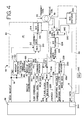
- FIG 4 it is a schematic block diagram of an external programmer 14 embodying the present invention for communicating with the cardiac device 12 of Figure 1.
- the external programmer 14 generally includes the programmer interface 48 and the programmer telemetry means or programmer head 42. Together, the programmer head 42 and the programmer interface 48 form the external programmer 14 which transmits command transmissions to the cardiac device 12 and receives information from the cardiac device 12.
- the programmer head 42 takes the form of a movable unit or wand which may be positioned externally to the patient in proximity to the cardiac device 12 implanted in the patient.
- the programmer head 42 includes the receive coil 38 and the transmit coil 40 for coupling electromagnetic energy with the antenna 36 of the cardiac device 12 ( Figures 1, 2 and 3).
- Coupled to the receive coil 38 is a programmer receiver section 44 for receiving information from the implantable cardiac device 12.
- Coupled to the transmit coil 40 is a programmer transmitter section 46 for transmitting program transmissions to the cardiac device 12.
- the wakeup generation 178 is coupled to the programmer interface 48.
- the wakeup generation 178 has an input 180 coupled to a send wakeup line 181, an output 182 for conveying the wakeup or initiation code and an output 184 coupled to wakeup response detection 186.
- the wakeup response detection 186 has an input 188, an enable input 189 coupled to send wakeup line 181, and an output 190 coupled to the programmer interface for conveying a wakeup acknowledged signal.
- the programmer transmitter section 46 also includes command encoder 192.
- the command encoder 192 is coupled to the programmer interface 48 by a command data bus 194, a control input 196, a control output 198, and a clock input 200 and has an output 202.
- the clock input 200 is coupled to a multiplexer 204. Responsive to select signals on select line 205, the multiplexer 204 selects one of two clock signals for clocking the transmission of data, including a high speed clock on line 206, preferably with a frequency of 131,072 Hz, and a low speed clock on line 208, preferably with a frequency of 2,048 Hz. Both clock signals are supplied by programmer interface 48.
- the output 182 of the wakeup generation 178 and the output 202 of the command encoder 192 are coupled to a multiplexer 210.
- the output of the multiplexer 210 responsive to a select signal on the send wakeup line 181 coupled to the select input 212 of the multiplexer 210, conveys serial data received from either output 182 or output 202 to an input 213 of a bit encoder 214.
- the bit encoder 214 encodes the digital data for driving the transmit coil 40.
- the command encoder 192 receives command transmissions in the form of digital data from the programmer interface 48 and serially shifts the data out at a rate determined by the clock signal at clock input 200. Command transmissions are sent in accordance with a first protocol. The command encoder 192 fashions or assembles the serial stream of bits which form the command transmissions in accordance with the first protocol. If the external programmer 14 is sending a command transmission which is not the initiation code, the multiplexer 210 conveys the output 202 of the command encoder 192 to the bit encoder 214. The bit encoder 214 drives the transmit coil 40 to pulse width modulate a carrier signal in accordance with the digital data received from multiplexer 210 at input 213.
- the programmer receiver section 44 includes a programmer receive amplifier 216 coupled to receive coil 38.
- the programmer receive amplifier 216 has an AGC input 218 coupled to an automatic gain control (AGC) 220.
- the programmer receive amplifier 216 also has an output 222 coupled to a programmer bit decoder 224 and the automatic gain control 220.
- the programmer bit decoder 224 has an output 226 coupled to the input 188 of the wakeup response detection 186 and to the input 228 of the response decoder 230.
- the response decoder 230 is coupled to the response data bus 232 which is also coupled to the programmer interface 48.
- the response decoder 230 also has two control outputs 236 and 238.
- the programmer receive amplifier 216 detects energy received by the receive coil 38 and amplifies it to voltage levels compatible with the programmer bit decoder 224.
- the programmer bit decoder 224 receives the amplified received signal and decodes the phase modulation encoded data as well as the carrier clock signal.
- the decoded data and the decoded clock signal are conveyed to the input 228 of the response decoder 230 and to the input 188 of the wakeup response detection 186.
- the response decoder 230 decodes the components of the transmitted information.
- the response decoder 230 parses the received data to decode the components of an outbound frame 54 ( Figure 2(b)) which are then conveyed to the programmer interface 48.
- the programmer interface 48 may then use these components for verifying the accuracy of the received information. For example, the programmer interface 48 may determine which, if any, received frames contained errors.
- the response decoder 230 provides a signal at control output 236 to indicate to the programmer interface 48 that a response has been received.
- the response decoder 230 provides a signal at control output 238 when it writes the response data to the response data bus 232.
- the automatic gain control 220 ensures that the level of the amplified received data from the programmer receive amplifier 216 is always within a range which can be interpreted by the programmer bit decoder 224. If the automatic gain control 220 cannot ensure the level, it may be due to the programmer head 42 being moved too far from the cardiac device 12.
- the automatic gain control 220 responds by providing a signal to the input 218 of programmer receive amplifier 216 which causes the amplification provided by programmer receive amplifier 216 to be varied.
- An automatic gain control digitizer 240 transforms the analog signal supplied by the automatic gain control 220 to the input 218 into a digital value and supplies the digital value to the programmer interface 48. The programmer interface 48 may use the digital value to determine how far from the implantable cardiac device the programmer head is located.
- the signal strength indicating means 242 provides an indication of received signal strength.
- the programmer interface 48 may include a signal strength determining means 244.
- the particular signal strength indicating means 242 and signal strength determining means 244 described herein do not form part of the invention, but represent background art useful for understanding the invention.
- the signal strength determining means 244 uses the digital value provided by the automatic gain control digitizer 240 to determine how far the programmer head 42 is from the cardiac device 12. The signal strength determining means 244 then conveys a signal to the signal strength indicating means 242 which in turn provides an indication.
- This indication may be visual, such as a light emitting diode array such as bargraph in which the number of illuminated light emitting diodes corresponds to received signal strength, or a flashing LED which flashes at: a rate dependent on signal strength, or audible such as a tone with pitch or volume indicative of received signal strength, or a combination of the three.
- the user in response to the indication, may then reposition the programmer head 42 to increase the received signal strength.
- the signal strength indicating means 242 provides user feedback to allow optimal placement of the programmer head 42 for optimum signal strength from the implanted cardiac device 12.
- FIG. 5 is a flow diagram illustrating the manner in which the programming unit of Figure 4 may be implemented for positioning the programming unit for optimal reception of signals from the implantable cardiac device of Figure 3.
- This process begins at step 246 with transmission of the initiation code to the implantable cardiac device 12 by the wakeup generation 178 of the programmer head 142.
- the wakeup generation 178 responds to a send wakeup (initiation) signal received at input 180 from programmer interface 48.
- the wakeup generation 178 conveys the initiation code to multiplexer 210.
- the multiplexer 210 conveys the initiation code to the bit encoder 214.
- the bit encoder 214 drives the transmit coil 40 and pulse wave modulates a carrier signal according to the initiation code.
- the external programmer 14 listens for a response.
- the wakeup detect 35 of the cardiac device 12 energizes the receive amplifier 86 ( Figure 3) to detect the energy transmitted by the programmer head 42. If the initiation code is detected by the cardiac device 12, the cardiac device 12 responds by transmitting information in the form of the response code.
- the response code acts as a locating signal for the programmer head 42.
- the external programmer 14 tests if a response code has been received. If the cardiac device 12 transmitted the response code, the programmer receive amplifier 216 may detect the code and the bit decoder 224 will decode the received response code. In response to the send wakeup signal at the input 189 to the wakeup response detection 186, the wakeup response detection 186 will compare the received response with the initiation code. If the response and the initiation codes match, the wakeup response detection 190 will signal the programmer interface 48 by placing a wakeup acknowledged signal on output 190.
- control is returned to step 246 and the initiation code is re-transmitted.
- the external programmer 14 determines the range from the programmer head 42 to the cardiac device 12 based on received signal strength. During this time, the cardiac device 12, which has detected the initiation code, responds by transmitting the response code to allow the external programmer 14 to lock on to the transmission and determine a received signal strength. There are multiple transmissions of the initiation code by the programmer 14; for every correct reception of the initiation code by the implant 12, the implant transmits the response code. The programmer 14 uses the multiple response codes to effectively lock on to the signal and determine a received signal strength.
- automatic gain control digitizer 240 supplies to the programmer interface 48 a digital value corresponding to the analog signal produced by the automatic gain control 220.
- the programmer interface 48 uses this digital value to determine the range from the programmer head 42 to the cardiac device 12. At step 254, the programmer interface 48 also uses this digital value to update the light emitting diode bargraph or other signal strength indicating means 242. The user can use this indication to move the programmer head 42 in relation to the implantation site of the cardiac device within the patient in order to properly locate the programmer head 42 for optimal transmission and receipt of telemetry signals.
- the initial command begins with the preamble 58 of an inbound frame 54.
- the preamble 58 must be clearly distinguishable from the initiation code. Therefore, the initiation code and the preamble preferably are digital bit streams that can't easily be produced from one another. This can be accomplished if the Hamming distance between the bit strings is large and remains large as one bit string is shifted with respect to the other bit string by one or two bits.
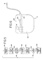
- FIG. 6 it is a front plan view of an implantable cardiac device 12 embodying the present invention.
- the cardiac device 12 of Figure 6 includes a hermetically sealed enclosure 260 defining a cavity having an open perimeter 262 and a header 264 sealingly engaging the perimeter 262.
- the cardiac monitor 12 further includes electrodes 16 for sensing activity of the heart, providing therapy to the heart, or both.
- the antenna 36 Within the header 264 is the antenna 36. Because the antenna 36 is located within the insulative header 264, efficient telemetry of data will be provided. Also disposed within the header 264 is one or more connectors 273. The connectors 273 may include one or more circuits as needed to connect one or more electrodes 16 as may be required by the cardiac device 12. The enclosure 260 may enclose the electrical circuitry previously described. The particular enclosure 260 and header 264 described herein do not form part of the invention, but represent background art useful for understanding the invention.
- the present invention provides a new and improved telemetry system comprising the telemetry means 28 of the implantable cardiac device 12 and the programmer telemetry means of the programmer head 42 of the external programmer 14.
- the improved telemetry system allows reduced power consumption within the implantable cardiac device 12, verification of accurate receipt of data and command transmissions, and accurate location of the external programmer head 42 relative to the implantation site of the implanted cardiac device 12.
Landscapes
- Health & Medical Sciences (AREA)
- Life Sciences & Earth Sciences (AREA)
- Animal Behavior & Ethology (AREA)
- Nuclear Medicine, Radiotherapy & Molecular Imaging (AREA)
- Radiology & Medical Imaging (AREA)
- Biomedical Technology (AREA)
- Engineering & Computer Science (AREA)
- General Health & Medical Sciences (AREA)
- Public Health (AREA)
- Veterinary Medicine (AREA)
- Biophysics (AREA)
- Heart & Thoracic Surgery (AREA)
- Electrotherapy Devices (AREA)
- Measuring And Recording Apparatus For Diagnosis (AREA)
Claims (14)
- Système (10) comportant un dispositif cardiaque (12) qui surveille l'activité d'un coeur humain, ou fournit une thérapie au coeur humain, ou les deux, le dispositif cardiaque (12) pouvant être implanté en dessous de la peau d'un patient et communiquant avec un récepteur (44) et un émetteur (46) extérieurs non-implantés, le dispositif cardiaque (12) comportant au moins une électrode (16) pour détecter l'activité du coeur ou fournir une thérapie au coeur et un circuit (20) relié à la au moins une électrode (16) pour fournir une thérapie ou surveiller l'activité du coeur détectée par la au moins une électrode, le circuit (20) comportant un processeur (22) pour produire des données représentatives de l'activité surveillée ou de l'activité thérapeutique conformément à des transmissions d'instruction reçues, comportant de plus :un récepteur (32) destiné à recevoir les transmissions d'instruction provenant de l'émetteur extérieur non-implanté (46), les transmissions d'instruction se conformant à un premier protocole et les transmissions d'instruction étant transmises de manière sélective à deux ou plus de deux vitesses conformément au premier protocole, et incluant une transmission d'instruction de déclenchement transmise de manière sélectionnée à une première vitesse relativement lente,un émetteur (34) destiné à transmettre des informations incluant les données au récepteur extérieur non-implanté (44) conformément à un second protocole, le premier protocole étant différent du second protocole, etun détecteur de réveil (35) sensible à la transmission d'une instruction de déclenchement pour mettre entièrement sous tension le récepteur (32) et l'émetteur (34).
- Système selon la revendication 1, caractérisé en outre en ce que le récepteur (44) et l'émetteur (46) extérieurs non-implantés sont dans un dispositif extérieur non-implantable.
- Système selon la revendication 2, caractérisé en outre en ce que l'émetteur (46) comporte un émetteur d'instructions (214) qui transmet les transmissions d'instruction de déclenchement à la première vitesse, relativement basse, avant qu'une liaison de communication ne soit établie entre l'émetteur implanté (34) et le récepteur (44), et l'émetteur d'instructions (214) transmet les transmissions d'instruction à une seconde vitesse, relativement plus rapide, après que la liaison de communication a été établie.
- Système selon la revendication 3, caractérisé en outre en ce que le récepteur implantable (32) a un décodeur d'instruction (100) destiné à décoder les transmissions d'instruction.
- Système selon la revendication 2, caractérisé en outre en ce que l'émetteur (46) situé dans le dispositif extérieur non-implantable (14) comporte un générateur de réveil (178) pour créer la transmission d'instruction de déclenchement.
- Système selon la revendication 5, caractérisé en outre en ce que la transmission d'instruction de déclenchement a une configuration binaire prédéterminée.
- Système selon la revendication 2, caractérisé en outre en ce que le récepteur implantable (32) répond à une instruction de réinitialisation transmise par l'émetteur (46) situé dans le dispositif extérieur non-implantable (14) en déclenchant le dispositif cardiaque (12) vers un état prédéterminé.
- Système selon la revendication 2, caractérisé en outre en ce que le détecteur de réveil (35) situé dans le dispositif cardiaque (12) permettant au récepteur implantable (32) de recevoir les transmissions d'instruction de déclenchement à des intervalles de temps ayant une durée commandée séparés par des intervalles de temps pendant lesquels le détecteur de réveil (35) invalide le récepteur implantable (32) vis-à-vis d'une réception des transmissions d'instruction de déclenchement.
- Système selon la revendication 8, caractérisé en outre en ce que le dispositif cardiaque (12) comporte une antenne unique (36) couplée au récepteur implantable (32) et à l'émetteur implantable (34) pour à la fois recevoir les transmissions d'instruction et transmettre les informations.
- Système selon la revendication 9, caractérisé en outre en ce que le récepteur implantable (32) comporte un amplificateur de réception (86), le détecteur de réveil (35) permettant à l'amplificateur de réception (86) de détecter l'instruction de déclenchement provenant de l'émetteur (46) pendant une période de temps prédéterminée pendant chaque intervalle constitué des intervalles de temps ayant une durée commandée.
- Système selon la revendication 10, caractérisé en outre en ce que le détecteur de réveil (35) valide l'émetteur implantable (34) et l'émetteur implantable (34) transmet un code de réponse au récepteur (44) en réponse à l'amplificateur de réception (86) détectant l'instruction de déclenchement.
- Système selon la revendication 11, caractérisé en outre en ce que le récepteur implantable (32) et l'émetteur implantable (34) ne sont pas sous tension lorsqu'ils ne sont pas validés.
- Procédé de communication d'un dispositif cardiaque (12), consistant à :détecter l'activité du coeur,produire des données représentatives de l'activité conformément à des transmissions d'instruction reçues,fournir un récepteur (32) et recevoir à partir d'un émetteur non-implanté (46) les transmissions d'instruction, les transmissions d'instruction se conformant à un premier protocole et étant transmises de manière sélective à deux ou plus de deux vitesses conformément au premier protocole, et comportant une transmission d'instruction de déclenchement transmise de manière sélective à une première vitesse relativement basse,mettre entièrement sous tension le récepteur (32) sensible à la transmission d'instruction de déclenchement, ettransmettre des informations incluant les données à un récepteur non-implanté (44) conformément à un second protocole, le second protocole étant différent du premier protocole.
- Procédé selon la revendication 13, caractérisé en outre en ce qu'il établit une liaison de communication entre un émetteur non-implanté (46) et le récepteur (32) et transmet les transmissions d'instruction de déclenchement à la première vitesse, relativement plus faible, avant que la liaison de communication ne soit établie et transmet les transmissions d'instruction à une seconde vitesse, relativement plus rapide, après que la liaison de communication a été établie.
Priority Applications (1)
| Application Number | Priority Date | Filing Date | Title |
|---|---|---|---|
| EP01124342A EP1174163A1 (fr) | 1993-01-07 | 1993-12-23 | Dispositif cardiaque implantable |
Applications Claiming Priority (2)
| Application Number | Priority Date | Filing Date | Title |
|---|---|---|---|
| US08/001,330 US5342408A (en) | 1993-01-07 | 1993-01-07 | Telemetry system for an implantable cardiac device |
| US1330 | 2007-11-01 |
Related Child Applications (1)
| Application Number | Title | Priority Date | Filing Date |
|---|---|---|---|
| EP01124342A Division EP1174163A1 (fr) | 1993-01-07 | 1993-12-23 | Dispositif cardiaque implantable |
Publications (3)
| Publication Number | Publication Date |
|---|---|
| EP0607638A2 EP0607638A2 (fr) | 1994-07-27 |
| EP0607638A3 EP0607638A3 (en) | 1996-07-31 |
| EP0607638B1 true EP0607638B1 (fr) | 2002-05-02 |
Family
ID=21695488
Family Applications (2)
| Application Number | Title | Priority Date | Filing Date |
|---|---|---|---|
| EP93250362A Expired - Lifetime EP0607638B1 (fr) | 1993-01-07 | 1993-12-23 | Système de télémétric pour dispositif cardiaque implantable |
| EP01124342A Withdrawn EP1174163A1 (fr) | 1993-01-07 | 1993-12-23 | Dispositif cardiaque implantable |
Family Applications After (1)
| Application Number | Title | Priority Date | Filing Date |
|---|---|---|---|
| EP01124342A Withdrawn EP1174163A1 (fr) | 1993-01-07 | 1993-12-23 | Dispositif cardiaque implantable |
Country Status (5)
| Country | Link |
|---|---|
| US (1) | US5342408A (fr) |
| EP (2) | EP0607638B1 (fr) |
| AU (1) | AU664349B2 (fr) |
| CA (1) | CA2112162C (fr) |
| DE (1) | DE69331875T2 (fr) |
Cited By (3)
| Publication number | Priority date | Publication date | Assignee | Title |
|---|---|---|---|---|
| US7668596B2 (en) | 2002-02-07 | 2010-02-23 | Cardiac Pacemakers, Inc. | Methods and apparatuses for implantable medical device telemetry power management |
| US8151127B2 (en) | 2000-07-26 | 2012-04-03 | Bridgestone Americas Tire Operations, Llc | System for conserving battery life in a battery operated device |
| US8266465B2 (en) | 2000-07-26 | 2012-09-11 | Bridgestone Americas Tire Operation, LLC | System for conserving battery life in a battery operated device |
Families Citing this family (353)
| Publication number | Priority date | Publication date | Assignee | Title |
|---|---|---|---|---|
| US5490862A (en) | 1991-04-12 | 1996-02-13 | Adams; John M. | Atrial defibrillator having patient activated modality |
| US5342402A (en) * | 1993-01-29 | 1994-08-30 | Medtronic, Inc. | Method and apparatus for detection and treatment of tachycardia and fibrillation |
| US5354316A (en) * | 1993-01-29 | 1994-10-11 | Medtronic, Inc. | Method and apparatus for detection and treatment of tachycardia and fibrillation |
| US5383909A (en) * | 1993-01-29 | 1995-01-24 | Medtronic, Inc. | Diagnostic telemetry system for an apparatus for detection and treatment of tachycardia and fibrillation |
| US5394879A (en) | 1993-03-19 | 1995-03-07 | Gorman; Peter G. | Biomedical response monitor-exercise equipment and technique using error correction |
| US5383912A (en) * | 1993-05-05 | 1995-01-24 | Intermedics, Inc. | Apparatus for high speed data communication between an external medical device and an implantable medical device |
| DE4329898A1 (de) | 1993-09-04 | 1995-04-06 | Marcus Dr Besson | Kabelloses medizinisches Diagnose- und Überwachungsgerät |
| US5476488A (en) * | 1993-12-15 | 1995-12-19 | Pacesetter, Inc. | Telemetry system power control for implantable medical devices |
| US6249703B1 (en) * | 1994-07-08 | 2001-06-19 | Medtronic, Inc. | Handheld patient programmer for implantable human tissue stimulator |
| DE4435602C2 (de) * | 1994-10-05 | 1998-07-16 | Gunter Preis | Verfahren und Vorrichtung zur Versorgung implantierter Meß-, Steuer- und Regelsysteme mit Energie und zum bidirektionalen Datentransfer |
| AU4131696A (en) * | 1994-10-12 | 1996-05-06 | Ael Industries, Inc. | Telemetry system for an implanted device |
| US5626630A (en) * | 1994-10-13 | 1997-05-06 | Ael Industries, Inc. | Medical telemetry system using an implanted passive transponder |
| US5629678A (en) * | 1995-01-10 | 1997-05-13 | Paul A. Gargano | Personal tracking and recovery system |
| FI111215B (fi) * | 1995-05-31 | 2003-06-30 | Polar Electro Oy | Telemetristä tiedonsiirtoa käyttävä menetelmä ja järjestelmä sydänsykkeen mittaukseen |
| US5759199A (en) * | 1995-08-02 | 1998-06-02 | Pacesetter, Inc. | System and method for ambulatory monitoring and programming of an implantable medical device |
| US5720770A (en) * | 1995-10-06 | 1998-02-24 | Pacesetter, Inc. | Cardiac stimulation system with enhanced communication and control capability |
| US5774501A (en) * | 1995-10-24 | 1998-06-30 | Halpern, Deceased; Peter H. | High speed multilevel symbol telemetry system for cardiac pacemakers |
| US5662691A (en) | 1995-11-22 | 1997-09-02 | Incontrol, Inc. | System and method for implanting an implantable cardiac device |
| US5813999A (en) | 1995-12-21 | 1998-09-29 | Incontrol, Inc. | Implantable atrial defibrillator providing reduced cardioversion discomfort |
| US5683432A (en) * | 1996-01-11 | 1997-11-04 | Medtronic, Inc. | Adaptive, performance-optimizing communication system for communicating with an implanted medical device |
| US5674249A (en) * | 1996-05-02 | 1997-10-07 | Incontrol, Inc. | Atrial defibrillation system having a portable communication device |
| FR2749175B1 (fr) * | 1996-06-04 | 1998-08-14 | Ela Medical Sa | Dispositif de filtrage des signaux emis par un appareil medical, notamment un appareil medical actif implante |
| US5814081A (en) | 1997-04-07 | 1998-09-29 | Incontrol, Inc. | Atrial flutter cardioverter and method |
| US6115634A (en) * | 1997-04-30 | 2000-09-05 | Medtronic, Inc. | Implantable medical device and method of manufacture |
| US5861019A (en) * | 1997-07-25 | 1999-01-19 | Medtronic Inc. | Implantable medical device microstrip telemetry antenna |
| US6068651A (en) * | 1998-03-26 | 2000-05-30 | Pacesetter, Inc. | Atrial defibrillation lock out feature |
| USRE38515E1 (en) | 1998-04-15 | 2004-05-18 | Cardiac Pacemakers, Inc. | Atrial defibrillation system having patient selectable atrial fibrillation detection |
| US6477424B1 (en) * | 1998-06-19 | 2002-11-05 | Medtronic, Inc. | Medical management system integrated programming apparatus for communication with an implantable medical device |
| US5910120A (en) | 1998-06-23 | 1999-06-08 | Incontrol, Inc. | Method and system for detecting dislodgment of an implanted right atrial endocardial lead |
| US5991662A (en) | 1998-06-23 | 1999-11-23 | Cardiac Pacemakers, Inc. | Method and system for detecting dislodgment of an implanted right atrial endocardial lead using sensing periods established with one other lead |
| US6067469A (en) | 1998-06-23 | 2000-05-23 | Cardiac Pacemakers, Inc. | Method and system for detecting dislodgment of an implanted right atrial endocardial lead using a sensing period derived from a ventricular lead |
| US6052617A (en) | 1998-07-01 | 2000-04-18 | Cardiac Pacemakers, Inc. | System and method for reliably detecting atrial events of a heart using only atrial sensing |
| US7231254B2 (en) | 1998-08-05 | 2007-06-12 | Bioneuronics Corporation | Closed-loop feedback-driven neuromodulation |
| US7209787B2 (en) | 1998-08-05 | 2007-04-24 | Bioneuronics Corporation | Apparatus and method for closed-loop intracranial stimulation for optimal control of neurological disease |
| US9375573B2 (en) | 1998-08-05 | 2016-06-28 | Cyberonics, Inc. | Systems and methods for monitoring a patient's neurological disease state |
| US7277758B2 (en) | 1998-08-05 | 2007-10-02 | Neurovista Corporation | Methods and systems for predicting future symptomatology in a patient suffering from a neurological or psychiatric disorder |
| US9042988B2 (en) | 1998-08-05 | 2015-05-26 | Cyberonics, Inc. | Closed-loop vagus nerve stimulation |
| US7324851B1 (en) | 1998-08-05 | 2008-01-29 | Neurovista Corporation | Closed-loop feedback-driven neuromodulation |
| US7242984B2 (en) | 1998-08-05 | 2007-07-10 | Neurovista Corporation | Apparatus and method for closed-loop intracranial stimulation for optimal control of neurological disease |
| US8762065B2 (en) | 1998-08-05 | 2014-06-24 | Cyberonics, Inc. | Closed-loop feedback-driven neuromodulation |
| US9113801B2 (en) | 1998-08-05 | 2015-08-25 | Cyberonics, Inc. | Methods and systems for continuous EEG monitoring |
| US7403820B2 (en) | 1998-08-05 | 2008-07-22 | Neurovista Corporation | Closed-loop feedback-driven neuromodulation |
| US9415222B2 (en) | 1998-08-05 | 2016-08-16 | Cyberonics, Inc. | Monitoring an epilepsy disease state with a supervisory module |
| US7747325B2 (en) | 1998-08-05 | 2010-06-29 | Neurovista Corporation | Systems and methods for monitoring a patient's neurological disease state |
| US6154675A (en) | 1998-10-27 | 2000-11-28 | Medtronic, Inc. | Resetting ERI/POR/PIR/indicators in implantable medical devices |
| US6016447A (en) * | 1998-10-27 | 2000-01-18 | Medtronic, Inc. | Pacemaker implant recognition |
| US6016448A (en) * | 1998-10-27 | 2000-01-18 | Medtronic, Inc. | Multilevel ERI for implantable medical devices |
| US6128528A (en) * | 1999-03-18 | 2000-10-03 | Medtronics, Inc. | Error code calculations for data stored in an implantable medical device |
| US6240317B1 (en) | 1999-04-30 | 2001-05-29 | Medtronic, Inc. | Telemetry system for implantable medical devices |
| US6169925B1 (en) | 1999-04-30 | 2001-01-02 | Medtronic, Inc. | Telemetry system for implantable medical devices |
| US6167312A (en) * | 1999-04-30 | 2000-12-26 | Medtronic, Inc. | Telemetry system for implantable medical devices |
| DE19930240A1 (de) | 1999-06-25 | 2000-12-28 | Biotronik Mess & Therapieg | Verfahren zur Datenabfrage bei der Implantatsnachsorge |
| DE19930241A1 (de) | 1999-06-25 | 2000-12-28 | Biotronik Mess & Therapieg | Verfahren zur Datenübertragung bei der Implantatsüberwachung |
| DE19930250A1 (de) | 1999-06-25 | 2001-02-15 | Biotronik Mess & Therapieg | Vorrichtung zur Überwachung von Daten insbesondere aus einem elektromedizinischen Implantat |
| DE19930256A1 (de) | 1999-06-25 | 2000-12-28 | Biotronik Mess & Therapieg | Implantat mit Nah- und Fernfeldtelemetrie |
| DE19930245A1 (de) | 1999-06-25 | 2000-12-28 | Biotronik Mess & Therapieg | Elektromedizinisches Implantat |
| DE19930263A1 (de) | 1999-06-25 | 2000-12-28 | Biotronik Mess & Therapieg | Verfahren und Vorrichtung zur Datenübertragung zwischen einem elektromedizinischen Implantat und einem externen Gerät |
| DE19930262A1 (de) | 1999-06-25 | 2000-12-28 | Biotronik Mess & Therapieg | Sender für die Telemetrieeinrichtung eines Implantats |
| US7181505B2 (en) * | 1999-07-07 | 2007-02-20 | Medtronic, Inc. | System and method for remote programming of an implantable medical device |
| US6687547B2 (en) | 1999-09-14 | 2004-02-03 | Medtronic, Inc. | Method and apparatus for communicating with an implantable medical device with DTMF tones |
| US6263246B1 (en) | 1999-09-14 | 2001-07-17 | Medtronic, Inc. | Method and apparatus for communications with an implantable device |
| US6361522B1 (en) * | 1999-10-21 | 2002-03-26 | Cardiac Pacemakers, Inc. | Drug delivery system for implantable cardiac device |
| US6628985B2 (en) * | 2000-12-18 | 2003-09-30 | Cardiac Pacemakers, Inc. | Data logging system for implantable medical device |
| US6480733B1 (en) | 1999-11-10 | 2002-11-12 | Pacesetter, Inc. | Method for monitoring heart failure |
| US6409675B1 (en) | 1999-11-10 | 2002-06-25 | Pacesetter, Inc. | Extravascular hemodynamic monitor |
| US6942622B1 (en) | 1999-11-10 | 2005-09-13 | Pacesetter, Inc. | Method for monitoring autonomic tone |
| US6562001B2 (en) | 2000-01-21 | 2003-05-13 | Medtronic Minimed, Inc. | Microprocessor controlled ambulatory medical apparatus with hand held communication device |
| US6400990B1 (en) * | 2000-02-18 | 2002-06-04 | Pacesetter, Inc. | Patient activated telemetry control unit using bidirectional asymmetric dual-mode telemetry link to communicate with an implanted device |
| US6895281B1 (en) | 2000-03-31 | 2005-05-17 | Cardiac Pacemakers, Inc. | Inductive coil apparatus for bio-medical telemetry |
| US6496705B1 (en) | 2000-04-18 | 2002-12-17 | Motorola Inc. | Programmable wireless electrode system for medical monitoring |
| US6441747B1 (en) | 2000-04-18 | 2002-08-27 | Motorola, Inc. | Wireless system protocol for telemetry monitoring |
| US6574503B2 (en) * | 2000-04-26 | 2003-06-03 | Medtronic, Inc. | GUI coding for identification of displayable data quality from medical devices |
| US6738670B1 (en) * | 2000-06-19 | 2004-05-18 | Medtronic, Inc. | Implantable medical device telemetry processor |
| US20070087637A1 (en) * | 2004-10-15 | 2007-04-19 | Zart Bryan J | Connector assembly for an implantable medical device and process for making |
| US7309262B2 (en) * | 2000-06-20 | 2007-12-18 | Medtronic, Inc. | Connector assembly for an implantable medical device and process for making |
| US6753791B2 (en) * | 2000-06-22 | 2004-06-22 | Halliburton Energy Services, Inc. | Burst QAM downhole telemetry system |
| WO2002005700A2 (fr) | 2000-07-18 | 2002-01-24 | Motorola, Inc. | Procede et systeme d'electrocardiographe sans fil |
| EP2272688B1 (fr) * | 2000-07-26 | 2012-02-01 | Bridgestone Americas Tire Operations, LLC | Système électronique de gestion de pneus |
| US6539253B2 (en) | 2000-08-26 | 2003-03-25 | Medtronic, Inc. | Implantable medical device incorporating integrated circuit notch filters |
| DE10049727A1 (de) * | 2000-09-28 | 2002-04-11 | Biotronik Mess & Therapieg | Elektrisch aktives Implantat |
| US7369890B2 (en) | 2000-11-02 | 2008-05-06 | Cardiac Pacemakers, Inc. | Technique for discriminating between coordinated and uncoordinated cardiac rhythms |
| US6567703B1 (en) * | 2000-11-08 | 2003-05-20 | Medtronic, Inc. | Implantable medical device incorporating miniaturized circuit module |
| US6505072B1 (en) | 2000-11-16 | 2003-01-07 | Cardiac Pacemakers, Inc. | Implantable electronic stimulator having isolation transformer input to telemetry circuits |
| US6574510B2 (en) * | 2000-11-30 | 2003-06-03 | Cardiac Pacemakers, Inc. | Telemetry apparatus and method for an implantable medical device |
| US6689117B2 (en) | 2000-12-18 | 2004-02-10 | Cardiac Pacemakers, Inc. | Drug delivery system for implantable medical device |
| US6675045B2 (en) | 2001-01-16 | 2004-01-06 | Cardiac Pacemakers, Inc. | Split-can dipole antenna for an implantable medical device |
| US6708065B2 (en) | 2001-03-02 | 2004-03-16 | Cardiac Pacemakers, Inc. | Antenna for an implantable medical device |
| US20030060695A1 (en) * | 2001-03-07 | 2003-03-27 | Connelly Patrick R. | Implantable artificial organ devices |
| US6662048B2 (en) * | 2001-03-30 | 2003-12-09 | Cardiac Pacemakers, Inc. | Implantable medical device with temperature measuring and storing capability |
| US7787958B2 (en) * | 2001-04-13 | 2010-08-31 | Greatbatch Ltd. | RFID detection and identification system for implantable medical lead systems |
| US7916013B2 (en) * | 2005-03-21 | 2011-03-29 | Greatbatch Ltd. | RFID detection and identification system for implantable medical devices |
| US6980857B2 (en) * | 2001-04-20 | 2005-12-27 | Cardiac Pacemakers, Inc. | Patient controlled atrial shock therapy |
| US6618617B2 (en) * | 2001-04-20 | 2003-09-09 | Cardiac Pacemakers, Inc. | Delay to therapy following patient controlled atrial shock therapy request |
| US7493162B2 (en) * | 2001-06-15 | 2009-02-17 | Cardiac Pacemakers, Inc. | Pulmonary vein stent for treating atrial fibrillation |
| US7209783B2 (en) * | 2001-06-15 | 2007-04-24 | Cardiac Pacemakers, Inc. | Ablation stent for treating atrial fibrillation |
| US6472991B1 (en) * | 2001-06-15 | 2002-10-29 | Alfred E. Mann Foundation For Scientific Research | Multichannel communication protocol configured to extend the battery life of an implantable device |
| US20030009204A1 (en) * | 2001-07-06 | 2003-01-09 | Amundson Mark D. | Adapative telemetry system and method for an implantable medical device |
| US20040127802A1 (en) * | 2001-07-17 | 2004-07-01 | Gmp Companies, Inc. | Wireless ECG system |
| US7197357B2 (en) | 2001-07-17 | 2007-03-27 | Life Sync Corporation | Wireless ECG system |
| US7933642B2 (en) | 2001-07-17 | 2011-04-26 | Rud Istvan | Wireless ECG system |
| US7047076B1 (en) | 2001-08-03 | 2006-05-16 | Cardiac Pacemakers, Inc. | Inverted-F antenna configuration for an implantable medical device |
| US6456256B1 (en) | 2001-08-03 | 2002-09-24 | Cardiac Pacemakers, Inc. | Circumferential antenna for an implantable medical device |
| US7903043B2 (en) * | 2003-12-22 | 2011-03-08 | Cardiac Pacemakers, Inc. | Radio frequency antenna in a header of an implantable medical device |
| US7340303B2 (en) * | 2001-09-25 | 2008-03-04 | Cardiac Pacemakers, Inc. | Evoked response sensing for ischemia detection |
| US8457743B2 (en) * | 2001-10-01 | 2013-06-04 | Medtronic, Inc. | Method of vagal stimulation to treat patients suffering from congestive heart failure |
| US20050137480A1 (en) * | 2001-10-01 | 2005-06-23 | Eckhard Alt | Remote control of implantable device through medical implant communication service band |
| US7778709B2 (en) * | 2001-10-01 | 2010-08-17 | Medtronic, Inc. | Method and device for using impedance measurements based on electrical energy of the heart |
| US7225029B2 (en) | 2001-10-26 | 2007-05-29 | Pacesetter, Inc. | Implantable cardiac therapy device with dual chamber can to isolate high-frequency circuitry |
| US6766200B2 (en) | 2001-11-01 | 2004-07-20 | Pacesetter, Inc. | Magnetic coupling antennas for implantable medical devices |
| US6763269B2 (en) | 2001-11-02 | 2004-07-13 | Pacesetter, Inc. | Frequency agile telemetry system for implantable medical device |
| US6842645B2 (en) | 2001-11-09 | 2005-01-11 | Pacesetter, Inc. | Presentation architecture for network supporting implantable cardiac therapy device |
| US7729776B2 (en) | 2001-12-19 | 2010-06-01 | Cardiac Pacemakers, Inc. | Implantable medical device with two or more telemetry systems |
| US6993393B2 (en) | 2001-12-19 | 2006-01-31 | Cardiac Pacemakers, Inc. | Telemetry duty cycle management system for an implantable medical device |
| US7096068B2 (en) * | 2002-01-17 | 2006-08-22 | Cardiac Pacemakers, Inc. | User-attachable or detachable telemetry module for medical devices |
| DE10216216A1 (de) * | 2002-04-05 | 2003-10-16 | Biotronik Mess & Therapieg | Anordnung und Verfahren zur Überwachung, Kalibrierung und Optimierung einer Steuerung eines elektromedizinischen Implantats |
| US7039462B2 (en) * | 2002-06-14 | 2006-05-02 | Cardiac Pacemakers, Inc. | Method and apparatus for detecting oscillations in cardiac rhythm |
| US7110823B2 (en) * | 2002-06-11 | 2006-09-19 | Advanced Bionics Corporation | RF telemetry link for establishment and maintenance of communications with an implantable device |
| US7089055B2 (en) * | 2002-06-28 | 2006-08-08 | Cardiac Pacemakers, Inc. | Method and apparatus for delivering pre-shock defibrillation therapy |
| US7554493B1 (en) * | 2002-07-08 | 2009-06-30 | Boston Scientific Neuromodulation Corporation | Folded monopole antenna for implanted medical device |
| US7103413B2 (en) * | 2002-07-12 | 2006-09-05 | Cardiac Pacemakers, Inc. | Ferrite core telemetry coil for implantable medical device |
| US7069086B2 (en) * | 2002-08-08 | 2006-06-27 | Cardiac Pacemakers, Inc. | Method and system for improved spectral efficiency of far field telemetry in a medical device |
| US7072711B2 (en) * | 2002-11-12 | 2006-07-04 | Cardiac Pacemakers, Inc. | Implantable device for delivering cardiac drug therapy |
| US7627373B2 (en) | 2002-11-30 | 2009-12-01 | Cardiac Pacemakers, Inc. | Method and apparatus for cell and electrical therapy of living tissue |
| US7072718B2 (en) * | 2002-12-03 | 2006-07-04 | Cardiac Pacemakers, Inc. | Antenna systems for implantable medical device telemetry |
| US7065409B2 (en) * | 2002-12-13 | 2006-06-20 | Cardiac Pacemakers, Inc. | Device communications of an implantable medical device and an external system |
| TWI235523B (en) * | 2002-12-31 | 2005-07-01 | Ind Tech Res Inst | A radio transmitter and receiver of an implantable medical device |
| AU2003303597A1 (en) | 2002-12-31 | 2004-07-29 | Therasense, Inc. | Continuous glucose monitoring system and methods of use |
| US8771183B2 (en) | 2004-02-17 | 2014-07-08 | Abbott Diabetes Care Inc. | Method and system for providing data communication in continuous glucose monitoring and management system |
| US7587287B2 (en) | 2003-04-04 | 2009-09-08 | Abbott Diabetes Care Inc. | Method and system for transferring analyte test data |
| US7016733B2 (en) * | 2003-04-23 | 2006-03-21 | Medtronic, Inc. | Telemetry antenna for an implantable medical device |
| US20040230247A1 (en) * | 2003-05-15 | 2004-11-18 | Stein Richard E. | Patient controlled therapy management and diagnostic device with human factors interface |
| US20040230246A1 (en) * | 2003-05-15 | 2004-11-18 | Stein Richard E. | Patient controlled therapy management and diagnostic device with human factors interface |
| US8066639B2 (en) | 2003-06-10 | 2011-11-29 | Abbott Diabetes Care Inc. | Glucose measuring device for use in personal area network |
| US7320675B2 (en) | 2003-08-21 | 2008-01-22 | Cardiac Pacemakers, Inc. | Method and apparatus for modulating cellular metabolism during post-ischemia or heart failure |
| US20050113886A1 (en) * | 2003-11-24 | 2005-05-26 | Fischell David R. | Implantable medical system with long range telemetry |
| WO2005061048A1 (fr) * | 2003-12-12 | 2005-07-07 | Medical Research Products-A, Inc. | Procede de telemetrie et appareil destine a un dispositif medical ambulatoire |
| US7515963B2 (en) * | 2003-12-16 | 2009-04-07 | Cardiac Pacemakers, Inc. | Method of patient initiated electro-cardiogram storage, status query and therapy activation |
| US7840263B2 (en) * | 2004-02-27 | 2010-11-23 | Cardiac Pacemakers, Inc. | Method and apparatus for device controlled gene expression |
| JP4705952B2 (ja) | 2004-04-07 | 2011-06-22 | カーディアック ペースメイカーズ, インコーポレイテッド | 埋込み型医療装置におけるrfトランシーバ・デューティ・サイクルのシステムと方法 |
| JP4705953B2 (ja) | 2004-04-07 | 2011-06-22 | カーディアック ペースメイカーズ, インコーポレイテッド | 埋込み型医療装置のrfウエイクアップ |
| US7375347B2 (en) * | 2004-04-26 | 2008-05-20 | Sensors For Medicine And Science, Inc. | Systems and methods for extending the useful life of optical sensors |
| US20080039898A1 (en) * | 2004-05-28 | 2008-02-14 | St. Jude Medical Ab | Implantable medical device |
| US7764995B2 (en) | 2004-06-07 | 2010-07-27 | Cardiac Pacemakers, Inc. | Method and apparatus to modulate cellular regeneration post myocardial infarct |
| US7519430B2 (en) * | 2004-06-17 | 2009-04-14 | Cardiac Pacemakers, Inc. | Dynamic telemetry encoding for an implantable medical device |
| US7457669B2 (en) * | 2004-06-17 | 2008-11-25 | Cardiac Pacemakers, Inc. | On-demand retransmission of data with an implantable medical device |
| US7539541B2 (en) * | 2004-08-09 | 2009-05-26 | Cardiac Pacemakers, Inc. | Automatic power control for a radio frequency transceiver of an implantable device |
| US7406349B2 (en) * | 2004-08-09 | 2008-07-29 | Cardiac Pacemakers, Inc. | Dynamic telemetry link selection for an implantable device |
| US7567841B2 (en) | 2004-08-20 | 2009-07-28 | Cardiac Pacemakers, Inc. | Method and apparatus for delivering combined electrical and drug therapies |
| JP2006075533A (ja) * | 2004-09-13 | 2006-03-23 | Olympus Corp | 被検体内導入システム、受信装置および被検体内導入装置 |
| US20070238988A1 (en) * | 2004-09-13 | 2007-10-11 | Tetsuo Minai | Body insertable system, receiving apparatus, and body insertable apparatus |
| US7720546B2 (en) * | 2004-09-30 | 2010-05-18 | Codman Neuro Sciences Sárl | Dual power supply switching circuitry for use in a closed system |
| US7167755B2 (en) | 2004-10-05 | 2007-01-23 | Cardiac Pacemakers, Inc. | Adaptive software configuration for a medical device |
| CA2583404A1 (fr) | 2004-10-20 | 2006-04-27 | Boston Scientific Limited | Systemes de stimulation cardiaque sans fil |
| US7647109B2 (en) | 2004-10-20 | 2010-01-12 | Boston Scientific Scimed, Inc. | Leadless cardiac stimulation systems |
| US7237712B2 (en) | 2004-12-01 | 2007-07-03 | Alfred E. Mann Foundation For Scientific Research | Implantable device and communication integrated circuit implementable therein |
| US8060219B2 (en) | 2004-12-20 | 2011-11-15 | Cardiac Pacemakers, Inc. | Epicardial patch including isolated extracellular matrix with pacing electrodes |
| US7981065B2 (en) | 2004-12-20 | 2011-07-19 | Cardiac Pacemakers, Inc. | Lead electrode incorporating extracellular matrix |
| US7218969B2 (en) * | 2005-01-19 | 2007-05-15 | Cardiac Pacemakers, Inc. | Dynamic channel selection for RF telemetry with implantable device |
| US7545272B2 (en) | 2005-02-08 | 2009-06-09 | Therasense, Inc. | RF tag on test strips, test strip vials and boxes |
| US8352040B2 (en) * | 2005-02-28 | 2013-01-08 | Cardiac Pacemakers, Inc. | Diversity antenna system for communication with an implantable medical device |
| US7392092B2 (en) * | 2005-02-28 | 2008-06-24 | Cardiac Pacemakers, Inc. | Method and apparatus for operating a diversity antenna system for communicating with implantable medical device |
| US7610065B2 (en) * | 2005-02-28 | 2009-10-27 | Cardiac Pacemakers, Inc. | Method and apparatus for antenna selection in a diversity antenna system for communicating with implantable medical device |
| US7868779B2 (en) * | 2005-04-04 | 2011-01-11 | Codman NeuroSciences Sárl | Circuitry for powering on and maintaining activation of a powered off electronic component |
| US7499748B2 (en) | 2005-04-11 | 2009-03-03 | Cardiac Pacemakers, Inc. | Transvascular neural stimulation device |
| US7664553B2 (en) * | 2005-04-27 | 2010-02-16 | Cardiac Pacemakers, Inc. | System and method for enabling communications with implantable medical devices |
| US8112240B2 (en) | 2005-04-29 | 2012-02-07 | Abbott Diabetes Care Inc. | Method and apparatus for providing leak detection in data monitoring and management systems |
| US7617003B2 (en) * | 2005-05-16 | 2009-11-10 | Cardiac Pacemakers, Inc. | System for selective activation of a nerve trunk using a transvascular reshaping lead |
| US8391990B2 (en) | 2005-05-18 | 2013-03-05 | Cardiac Pacemakers, Inc. | Modular antitachyarrhythmia therapy system |
| US7801620B2 (en) * | 2005-08-29 | 2010-09-21 | Cardiac Pacemakers, Inc. | RF telemetry link quality assessment system and method |
| US8380320B2 (en) * | 2005-09-12 | 2013-02-19 | Medtronic, Inc. | Implantable medical device communication system with macro and micro sampling intervals |
| US7616990B2 (en) | 2005-10-24 | 2009-11-10 | Cardiac Pacemakers, Inc. | Implantable and rechargeable neural stimulator |
| US7766829B2 (en) | 2005-11-04 | 2010-08-03 | Abbott Diabetes Care Inc. | Method and system for providing basal profile modification in analyte monitoring and management systems |
| US7686768B2 (en) * | 2005-11-23 | 2010-03-30 | Vital Sensors Holding Company, Inc. | Implantable pressure monitor |
| US7682313B2 (en) | 2005-11-23 | 2010-03-23 | Vital Sensors Holding Company, Inc. | Implantable pressure monitor |
| US7848823B2 (en) | 2005-12-09 | 2010-12-07 | Boston Scientific Scimed, Inc. | Cardiac stimulation system |
| US8050774B2 (en) | 2005-12-22 | 2011-11-01 | Boston Scientific Scimed, Inc. | Electrode apparatus, systems and methods |
| US8725243B2 (en) | 2005-12-28 | 2014-05-13 | Cyberonics, Inc. | Methods and systems for recommending an appropriate pharmacological treatment to a patient for managing epilepsy and other neurological disorders |
| US8868172B2 (en) | 2005-12-28 | 2014-10-21 | Cyberonics, Inc. | Methods and systems for recommending an appropriate action to a patient for managing epilepsy and other neurological disorders |
| US20100191306A1 (en) * | 2006-01-25 | 2010-07-29 | Greatbatch Ltd. | Transient voltage suppression circuit for an implanted rfid chip |
| US8248232B2 (en) | 2006-01-25 | 2012-08-21 | Greatbatch Ltd. | Hermetically sealed RFID microelectronic chip connected to a biocompatible RFID antenna |
| US7937161B2 (en) | 2006-03-31 | 2011-05-03 | Boston Scientific Scimed, Inc. | Cardiac stimulation electrodes, delivery devices, and implantation configurations |
| US8226891B2 (en) | 2006-03-31 | 2012-07-24 | Abbott Diabetes Care Inc. | Analyte monitoring devices and methods therefor |
| US8805526B2 (en) * | 2006-05-03 | 2014-08-12 | Cardiac Pacemakers, Inc. | Configurable medical telemetry radio system |
| US7613522B2 (en) * | 2006-06-09 | 2009-11-03 | Cardiac Pacemakers, Inc. | Multi-antenna for an implantable medical device |
| US7720544B2 (en) * | 2006-06-09 | 2010-05-18 | Cardiac Pacemakers, Inc. | Systems for enabling telemetry in an implantable medical device |
| EP2034885A4 (fr) | 2006-06-23 | 2010-12-01 | Neurovista Corp | Systeme et procede de surveillance tres peu invasifs |
| US8185204B2 (en) | 2006-07-12 | 2012-05-22 | Cardiac Pacemakers, Inc. | Implantable medical device telemetry with adaptive frequency hopping |
| US7623922B2 (en) * | 2006-07-12 | 2009-11-24 | Cardiac Pacemakers, Inc. | Implantable medical device telemetry with periodic frequency hopping |
| US7840281B2 (en) | 2006-07-21 | 2010-11-23 | Boston Scientific Scimed, Inc. | Delivery of cardiac stimulation devices |
| US8290600B2 (en) * | 2006-07-21 | 2012-10-16 | Boston Scientific Scimed, Inc. | Electrical stimulation of body tissue using interconnected electrode assemblies |
| US8838251B2 (en) | 2006-07-28 | 2014-09-16 | Medtronic, Inc. | Variable implantable medical device power characteristics based upon data or device type |
| US7769456B2 (en) * | 2006-09-01 | 2010-08-03 | Cardiac Pacemakers, Inc. | Frequency-agile system for telemetry with implantable device |
| US10420948B2 (en) * | 2006-10-30 | 2019-09-24 | Medtronic, Inc. | Implantable medical device with variable data retransmission characteristics based upon data type |
| US8295934B2 (en) | 2006-11-14 | 2012-10-23 | Neurovista Corporation | Systems and methods of reducing artifact in neurological stimulation systems |
| US7650191B1 (en) | 2007-01-16 | 2010-01-19 | Pacesetter, Inc. | Implantable medical device having a header with an integrated telemetry coil |
| EP2126785A2 (fr) | 2007-01-25 | 2009-12-02 | NeuroVista Corporation | Systèmes et procédés d'identification d'un état contre-critique chez un sujet |
| WO2008092133A2 (fr) | 2007-01-25 | 2008-07-31 | Neurovista Corporation | Procédés et systèmes permettant de mesurer la prédisposition d'une personne à avoir une crise |
| US20080199894A1 (en) | 2007-02-15 | 2008-08-21 | Abbott Diabetes Care, Inc. | Device and method for automatic data acquisition and/or detection |
| US8123686B2 (en) | 2007-03-01 | 2012-02-28 | Abbott Diabetes Care Inc. | Method and apparatus for providing rolling data in communication systems |
| US8046079B2 (en) | 2007-03-13 | 2011-10-25 | Cardiac Pacemakers, Inc. | Implantable medical device telemetry with hop-on-error frequency hopping |
| US8036736B2 (en) | 2007-03-21 | 2011-10-11 | Neuro Vista Corporation | Implantable systems and methods for identifying a contra-ictal condition in a subject |
| US20100106222A1 (en) * | 2007-03-27 | 2010-04-29 | St Jude Medical Ab | Method and system for initiating communication between a home monitoring device and an implantable medical device |
| US8461985B2 (en) | 2007-05-08 | 2013-06-11 | Abbott Diabetes Care Inc. | Analyte monitoring system and methods |
| US8665091B2 (en) | 2007-05-08 | 2014-03-04 | Abbott Diabetes Care Inc. | Method and device for determining elapsed sensor life |
| US7928850B2 (en) | 2007-05-08 | 2011-04-19 | Abbott Diabetes Care Inc. | Analyte monitoring system and methods |
| US8456301B2 (en) | 2007-05-08 | 2013-06-04 | Abbott Diabetes Care Inc. | Analyte monitoring system and methods |
| CN103251414B (zh) | 2007-06-21 | 2017-05-24 | 雅培糖尿病护理公司 | 用于分析物水平的检测的设备 |
| EP2171031B1 (fr) | 2007-06-21 | 2018-12-05 | Abbott Diabetes Care Inc. | Dispositifs et procédés de gestion de la santé |
| US9788744B2 (en) | 2007-07-27 | 2017-10-17 | Cyberonics, Inc. | Systems for monitoring brain activity and patient advisory device |
| DE102007040038A1 (de) * | 2007-08-24 | 2009-02-26 | Biotronik Crm Patent Ag | Anordnung und Verfahren zur Übertragung und Aktivierung einer Mehrzahl von Steuerdaten |
| US20090069862A1 (en) * | 2007-09-11 | 2009-03-12 | Brian Michael Shelton | Adaptive Telemetry Wakeup for an Implantable Medical Device |
| US20090088732A1 (en) * | 2007-10-02 | 2009-04-02 | Daniel Hernandez Villegas | Rapid Refill Programming for Implantable Drug Pump |
| US9129047B2 (en) | 2007-10-03 | 2015-09-08 | Medallion Therapeutics, Inc. | Programming and bolus monitoring device for an implantable drug pump |
| US7794384B2 (en) * | 2007-12-07 | 2010-09-14 | Terumo Heart, Inc. | Dual communication interface for artificial heart system |
| US20090171168A1 (en) | 2007-12-28 | 2009-07-02 | Leyde Kent W | Systems and Method for Recording Clinical Manifestations of a Seizure |
| US9259591B2 (en) | 2007-12-28 | 2016-02-16 | Cyberonics, Inc. | Housing for an implantable medical device |
| US8738147B2 (en) | 2008-02-07 | 2014-05-27 | Cardiac Pacemakers, Inc. | Wireless tissue electrostimulation |
| US7917226B2 (en) * | 2008-04-23 | 2011-03-29 | Enteromedics Inc. | Antenna arrangements for implantable therapy device |
| CN102149425B (zh) | 2008-09-10 | 2014-11-05 | 海德威公司 | 用于植入医疗设备的tet系统 |
| CA2776502A1 (fr) * | 2008-10-10 | 2010-04-15 | Peter Forsell | Chargeur pour implant |
| US8849390B2 (en) | 2008-12-29 | 2014-09-30 | Cyberonics, Inc. | Processing for multi-channel signals |
| US8588933B2 (en) | 2009-01-09 | 2013-11-19 | Cyberonics, Inc. | Medical lead termination sleeve for implantable medical devices |
| US9345892B2 (en) * | 2009-01-30 | 2016-05-24 | Medtronic, Inc. | Transceiver duty cycled operational mode |
| US20100198279A1 (en) * | 2009-01-30 | 2010-08-05 | Corndorf Eric D | Transceiver duty cycled operational mode |
| WO2010127050A1 (fr) | 2009-04-28 | 2010-11-04 | Abbott Diabetes Care Inc. | Détection d'erreur dans des données de répétition critiques dans un système de capteur sans fil |
| WO2010138856A1 (fr) | 2009-05-29 | 2010-12-02 | Abbott Diabetes Care Inc. | Systèmes d'antenne de dispositif médical comportant des configurations d'antenne externe |
| US8786624B2 (en) | 2009-06-02 | 2014-07-22 | Cyberonics, Inc. | Processing for multi-channel signals |
| WO2011026147A1 (fr) | 2009-08-31 | 2011-03-03 | Abbott Diabetes Care Inc. | Dispositif et procédés de traitement de signal d'analyte |
| JP5795584B2 (ja) | 2009-08-31 | 2015-10-14 | アボット ダイアベティス ケア インコーポレイテッドAbbott Diabetes Care Inc. | 医療用装置 |
| EP2473099A4 (fr) | 2009-08-31 | 2015-01-14 | Abbott Diabetes Care Inc | Système de surveillance de substance à analyser et procédés de gestion de l'énergie et du bruit |
| US9643019B2 (en) | 2010-02-12 | 2017-05-09 | Cyberonics, Inc. | Neurological monitoring and alerts |
| WO2011111008A1 (fr) | 2010-03-11 | 2011-09-15 | Ecole Polytechnique Federale De Lausanne (Epfl) | Système de télémesure pour applications de détection dans des milieux à perte |
| EP2637554B1 (fr) * | 2010-11-08 | 2014-09-17 | Koninklijke Philips N.V. | Système et procédé pour échanger des informations de cycle d'utilisation dans des réseaux sans fil |
| CN103619255B (zh) | 2011-02-28 | 2016-11-02 | 雅培糖尿病护理公司 | 与分析物监测装置关联的装置、系统和方法以及结合了它们的装置 |
| US8954148B2 (en) | 2011-06-28 | 2015-02-10 | Greatbatch, Ltd. | Key fob controller for an implantable neurostimulator |
| US20130006330A1 (en) | 2011-06-28 | 2013-01-03 | Greatbatch, Ltd. | Dual patient controllers |
| US20130197607A1 (en) | 2011-06-28 | 2013-08-01 | Greatbatch Ltd. | Dual patient controllers |
| US9069536B2 (en) | 2011-10-31 | 2015-06-30 | Abbott Diabetes Care Inc. | Electronic devices having integrated reset systems and methods thereof |
| CA2840640C (fr) | 2011-11-07 | 2020-03-24 | Abbott Diabetes Care Inc. | Dispositif et procedes de controle de substance a analyser |
| US9098610B2 (en) * | 2011-12-22 | 2015-08-04 | Greatbatch Ltd. | Communication for implantable medical devices |
| US8761717B1 (en) | 2012-08-07 | 2014-06-24 | Brian K. Buchheit | Safety feature to disable an electronic device when a wireless implantable medical device (IMD) is proximate |
| US9968306B2 (en) | 2012-09-17 | 2018-05-15 | Abbott Diabetes Care Inc. | Methods and apparatuses for providing adverse condition notification with enhanced wireless communication range in analyte monitoring systems |
| WO2014052900A1 (fr) * | 2012-09-27 | 2014-04-03 | Second Sight Medical Products, Inc. | Dispositif médical comportant une bobine implantable, bobine externe et indicateur d'intensité de signal |
| US9095724B2 (en) * | 2013-02-25 | 2015-08-04 | Boston Scientific Neuromodulation Corporation | Neuromodulation system with dual telemetry system |
| WO2014146016A2 (fr) | 2013-03-15 | 2014-09-18 | Alfred E. Mann Foundation For Scientific Research | Stimulateurs de courant à sorties multiples, détection de courant et allumage rapide |
| CA3075310C (fr) | 2013-07-29 | 2022-04-05 | Alfred E. Mann Foundation For Scientific Research | Circuit d'attaque de classe e commande par microprocesseur |
| AU2015204701B2 (en) | 2014-01-10 | 2018-03-15 | Cardiac Pacemakers, Inc. | Systems and methods for detecting cardiac arrhythmias |
| US20150196769A1 (en) | 2014-01-10 | 2015-07-16 | Cardiac Pacemakers, Inc. | Methods and systems for improved communication between medical devices |
| US9757570B2 (en) | 2014-08-06 | 2017-09-12 | Cardiac Pacemakers, Inc. | Communications in a medical device system |
| US9694189B2 (en) | 2014-08-06 | 2017-07-04 | Cardiac Pacemakers, Inc. | Method and apparatus for communicating between medical devices |
| US9808631B2 (en) | 2014-08-06 | 2017-11-07 | Cardiac Pacemakers, Inc. | Communication between a plurality of medical devices using time delays between communication pulses to distinguish between symbols |
| CN106659882A (zh) | 2014-08-15 | 2017-05-10 | 艾克索尼克斯调制技术股份有限公司 | 用于进行神经刺激以减轻膀胱功能障碍和其他适应症的可植入引线附着结构 |
| EP3180071B1 (fr) | 2014-08-15 | 2021-09-22 | Axonics, Inc. | Dispositif de générateur d'impulsion externe et systèmè associé pour une stimulation nerveuse d'essai |
| WO2016025915A1 (fr) | 2014-08-15 | 2016-02-18 | Axonics Modulation Technologies, Inc. | Programmateur clinicien électromyographique intégré destiné à être utilisé avec un neurostimulateur implantable |
| US9855423B2 (en) | 2014-08-15 | 2018-01-02 | Axonics Modulation Technologies, Inc. | Systems and methods for neurostimulation electrode configurations based on neural localization |
| EP3180072B1 (fr) | 2014-08-15 | 2018-11-28 | Axonics Modulation Technologies Inc. | Positionnement d'une dérivation électromyographique et titrage de la stimulation dans un système de stimulation nerveuse pour le traitement de la vessie hyperactive |
| US9526909B2 (en) | 2014-08-28 | 2016-12-27 | Cardiac Pacemakers, Inc. | Medical device with triggered blanking period |
| CN107427685B (zh) | 2015-01-09 | 2021-09-21 | 艾克索尼克斯股份有限公司 | 与神经刺激充电设备一起使用的附接设备及相关联方法 |
| AU2016205047B2 (en) | 2015-01-09 | 2020-07-02 | Axonics Modulation Technologies, Inc. | Patient remote and associated methods of use with a nerve stimulation system |
| EP3242718B1 (fr) | 2015-01-09 | 2019-05-08 | Axonics Modulation Technologies, Inc. | Antenne améliorée et procédés d'utilisation pour un stimulateur nerveux implantable |
| ES2713231T3 (es) | 2015-02-06 | 2019-05-20 | Cardiac Pacemakers Inc | Sistemas para el suministro seguro de una terapia de estimulación eléctrica |
| EP3827877B1 (fr) | 2015-02-06 | 2024-06-19 | Cardiac Pacemakers, Inc. | Systèmes de traitement d'arythmies cardiaques |
| WO2016130477A2 (fr) | 2015-02-09 | 2016-08-18 | Cardiac Pacemakers, Inc. | Dispositif médical implantable comportant une étiquette d'identification radio-opaque |
| EP3265172B1 (fr) | 2015-03-04 | 2018-12-19 | Cardiac Pacemakers, Inc. | Systèmes de traitement d'arythmies cardiaques |
| US10050700B2 (en) | 2015-03-18 | 2018-08-14 | Cardiac Pacemakers, Inc. | Communications in a medical device system with temporal optimization |
| CN107427222B (zh) | 2015-03-18 | 2021-02-09 | 心脏起搏器股份公司 | 使用链路质量评估的医疗设备系统中的通信 |
| CN107847731B (zh) | 2015-07-10 | 2019-06-28 | 艾克索尼克斯调制技术股份有限公司 | 具有无asic的内部电子设备的可植入神经刺激器以及使用方法 |
| WO2017031347A1 (fr) | 2015-08-20 | 2017-02-23 | Cardiac Pacemakers, Inc. | Systèmes et procédés de communication entre des dispositifs médicaux |
| US9853743B2 (en) | 2015-08-20 | 2017-12-26 | Cardiac Pacemakers, Inc. | Systems and methods for communication between medical devices |
| US9968787B2 (en) | 2015-08-27 | 2018-05-15 | Cardiac Pacemakers, Inc. | Spatial configuration of a motion sensor in an implantable medical device |
| US9956414B2 (en) | 2015-08-27 | 2018-05-01 | Cardiac Pacemakers, Inc. | Temporal configuration of a motion sensor in an implantable medical device |
| WO2017040115A1 (fr) | 2015-08-28 | 2017-03-09 | Cardiac Pacemakers, Inc. | Système de détection de tamponnade |
| US10226631B2 (en) | 2015-08-28 | 2019-03-12 | Cardiac Pacemakers, Inc. | Systems and methods for infarct detection |
| US10137305B2 (en) | 2015-08-28 | 2018-11-27 | Cardiac Pacemakers, Inc. | Systems and methods for behaviorally responsive signal detection and therapy delivery |
| WO2017044389A1 (fr) | 2015-09-11 | 2017-03-16 | Cardiac Pacemakers, Inc. | Détection et confirmation d'arythmie |
| US10065041B2 (en) | 2015-10-08 | 2018-09-04 | Cardiac Pacemakers, Inc. | Devices and methods for adjusting pacing rates in an implantable medical device |
| JP6608063B2 (ja) | 2015-12-17 | 2019-11-20 | カーディアック ペースメイカーズ, インコーポレイテッド | 植込み型医療装置 |
| US10905886B2 (en) | 2015-12-28 | 2021-02-02 | Cardiac Pacemakers, Inc. | Implantable medical device for deployment across the atrioventricular septum |
| WO2017127548A1 (fr) | 2016-01-19 | 2017-07-27 | Cardiac Pacemakers, Inc. | Dispositifs permettant de recharger sans fil une batterie rechargeable d'un dispositif médical implantable |
| WO2017132374A1 (fr) | 2016-01-29 | 2017-08-03 | Axonics Modulation Technologies, Inc. | Procédés et systèmes pour ajustement de fréquence pour optimiser la charge d'un neurostimulateur implantable |
| WO2017136548A1 (fr) | 2016-02-04 | 2017-08-10 | Cardiac Pacemakers, Inc. | Système de pose avec capteur de force pour dispositif cardiaque sans fil |
| CN108697897B (zh) | 2016-02-12 | 2023-01-13 | 艾克索尼克斯股份有限公司 | 用于试验神经刺激的外部脉冲发生器设备和相关联方法 |
| US10220215B2 (en) | 2016-03-29 | 2019-03-05 | Boston Scientific Neuromodulation Corporation | Far-field short-range radio-frequency antenna on the side of an implantable medical device case |
| US11116988B2 (en) | 2016-03-31 | 2021-09-14 | Cardiac Pacemakers, Inc. | Implantable medical device with rechargeable battery |
| US10328272B2 (en) | 2016-05-10 | 2019-06-25 | Cardiac Pacemakers, Inc. | Retrievability for implantable medical devices |
| US10668294B2 (en) | 2016-05-10 | 2020-06-02 | Cardiac Pacemakers, Inc. | Leadless cardiac pacemaker configured for over the wire delivery |
| JP6764956B2 (ja) | 2016-06-27 | 2020-10-07 | カーディアック ペースメイカーズ, インコーポレイテッド | 再同期ペーシング管理に皮下で感知されたp波を使用する心臓治療法システム |
| US11207527B2 (en) | 2016-07-06 | 2021-12-28 | Cardiac Pacemakers, Inc. | Method and system for determining an atrial contraction timing fiducial in a leadless cardiac pacemaker system |
| WO2018009392A1 (fr) | 2016-07-07 | 2018-01-11 | Cardiac Pacemakers, Inc. | Stimulateur cardiaque sans fil utilisant des mesures de pression pour la vérification de la capture de stimulation |
| CN109475743B (zh) | 2016-07-20 | 2022-09-02 | 心脏起搏器股份公司 | 在无引线心脏起搏器系统中利用心房收缩定时基准的系统 |
| WO2018035343A1 (fr) | 2016-08-19 | 2018-02-22 | Cardiac Pacemakers, Inc. | Dispositif médical implantable trans-septal |
| CN109640809B (zh) | 2016-08-24 | 2021-08-17 | 心脏起搏器股份公司 | 使用p波到起搏定时的集成式多装置心脏再同步治疗 |
| EP3503970B1 (fr) | 2016-08-24 | 2023-01-04 | Cardiac Pacemakers, Inc. | Resynchronisation cardiaque utilisant l'encouragement de la fusion pour la gestion de la synchronisation |
| WO2018057318A1 (fr) | 2016-09-21 | 2018-03-29 | Cardiac Pacemakers, Inc. | Dispositif de stimulation sans fil muni d'un boîtier qui abrite des composants interne du dispositif de stimulation sans fil et fonctionne comme boîtier de batterie et borne d'une batterie interne |
| US10758737B2 (en) | 2016-09-21 | 2020-09-01 | Cardiac Pacemakers, Inc. | Using sensor data from an intracardially implanted medical device to influence operation of an extracardially implantable cardioverter |
| WO2018057626A1 (fr) | 2016-09-21 | 2018-03-29 | Cardiac Pacemakers, Inc. | Moniteur cardiaque implantable |
| AU2017350759B2 (en) | 2016-10-27 | 2019-10-17 | Cardiac Pacemakers, Inc. | Implantable medical device with pressure sensor |
| US10413733B2 (en) | 2016-10-27 | 2019-09-17 | Cardiac Pacemakers, Inc. | Implantable medical device with gyroscope |
| WO2018081275A1 (fr) | 2016-10-27 | 2018-05-03 | Cardiac Pacemakers, Inc. | Thérapie de resynchronisation cardiaque à dispositifs multiples avec des améliorations de synchronisation |
| US10758724B2 (en) | 2016-10-27 | 2020-09-01 | Cardiac Pacemakers, Inc. | Implantable medical device delivery system with integrated sensor |
| WO2018081237A1 (fr) | 2016-10-27 | 2018-05-03 | Cardiac Pacemakers, Inc. | Utilisation d'un dispositif séparé pour gérer l'énergie d'impulsion de stimulation d'un stimulateur cardiaque |
| WO2018081133A1 (fr) | 2016-10-27 | 2018-05-03 | Cardiac Pacemakers, Inc. | Dispositif médical implantable présentant un canal d'écoute à réglage de rendement |
| EP3532157B1 (fr) | 2016-10-31 | 2020-08-26 | Cardiac Pacemakers, Inc. | Systèmes de stimulation de niveau d'activité |
| US10434317B2 (en) | 2016-10-31 | 2019-10-08 | Cardiac Pacemakers, Inc. | Systems and methods for activity level pacing |
| WO2018089311A1 (fr) | 2016-11-08 | 2018-05-17 | Cardiac Pacemakers, Inc | Dispositif médical implantable pour déploiement auriculaire |
| WO2018089308A1 (fr) | 2016-11-09 | 2018-05-17 | Cardiac Pacemakers, Inc. | Systèmes, dispositifs et procédés pour régler des paramètres d'impulsion de stimulation cardiaque pour un dispositif de stimulation cardiaque |
| CN109982746B (zh) | 2016-11-21 | 2023-04-04 | 心脏起搏器股份公司 | 提供心脏再同步治疗的无引线心脏起搏器 |
| US10881869B2 (en) | 2016-11-21 | 2021-01-05 | Cardiac Pacemakers, Inc. | Wireless re-charge of an implantable medical device |
| US10639486B2 (en) | 2016-11-21 | 2020-05-05 | Cardiac Pacemakers, Inc. | Implantable medical device with recharge coil |
| EP3541473B1 (fr) | 2016-11-21 | 2020-11-11 | Cardiac Pacemakers, Inc. | Stimulateur cardiaque sans sonde à communication multimodale |
| EP3541472B1 (fr) | 2016-11-21 | 2023-06-07 | Cardiac Pacemakers, Inc. | Dispositif médical implantable comportant un boîtier magnétiquement perméable et une bobine inductive placée autour du boîtier |
| US11207532B2 (en) | 2017-01-04 | 2021-12-28 | Cardiac Pacemakers, Inc. | Dynamic sensing updates using postural input in a multiple device cardiac rhythm management system |
| US11040209B2 (en) | 2017-01-19 | 2021-06-22 | Boston Scienitific Neuromodulation Corporation | Radio frequency antenna capacitively coupled to a charging coil in an implantable medical device |
| CN110234392B (zh) | 2017-01-26 | 2023-08-11 | 心脏起搏器股份公司 | 具有被包覆模制的组件的无引线装置 |
| CN110198759B (zh) | 2017-01-26 | 2023-08-11 | 心脏起搏器股份公司 | 具有可拆卸固定件的无引线可植入装置 |
| JP7000438B2 (ja) | 2017-01-26 | 2022-01-19 | カーディアック ペースメイカーズ, インコーポレイテッド | 冗長メッセージ送信を伴う人体デバイス通信 |
| US10821288B2 (en) | 2017-04-03 | 2020-11-03 | Cardiac Pacemakers, Inc. | Cardiac pacemaker with pacing pulse energy adjustment based on sensed heart rate |
| US10905872B2 (en) | 2017-04-03 | 2021-02-02 | Cardiac Pacemakers, Inc. | Implantable medical device with a movable electrode biased toward an extended position |
| EP3668592B1 (fr) | 2017-08-18 | 2021-11-17 | Cardiac Pacemakers, Inc. | Dispositif médical implantable avec capteur de pression |
| WO2019036568A1 (fr) | 2017-08-18 | 2019-02-21 | Cardiac Pacemakers, Inc. | Dispositif médical implantable comprenant un concentrateur de flux et une bobine de réception disposée autour du concentrateur de flux |
| JP6938778B2 (ja) | 2017-09-20 | 2021-09-22 | カーディアック ペースメイカーズ, インコーポレイテッド | 複数の作動モードを備えた移植式医療用装置 |
| US11185703B2 (en) | 2017-11-07 | 2021-11-30 | Cardiac Pacemakers, Inc. | Leadless cardiac pacemaker for bundle of his pacing |
| EP3717063B1 (fr) | 2017-12-01 | 2023-12-27 | Cardiac Pacemakers, Inc. | Systèmes pour détecter des repères de synchronisation de contraction auriculaire et pour déterminer un intervalle cardiaque à partir d'un stimulateur cardiaque sans fil implanté de manière ventriculaire |
| EP3717059B1 (fr) | 2017-12-01 | 2024-11-20 | Cardiac Pacemakers, Inc. | Systèmes pour détecter des repères de synchronisation de contraction auriculaire dans une fenêtre de recherche à partir d'un stimulateur cardiaque sans fil implanté de manière ventriculaire |
| EP3717060B1 (fr) | 2017-12-01 | 2022-10-05 | Cardiac Pacemakers, Inc. | Stimulateur cardiaque sans fil à comportement réversible |
| WO2019108545A1 (fr) | 2017-12-01 | 2019-06-06 | Cardiac Pacemakers, Inc. | Procédés et systèmes pour détecter des repères de synchronisation de contraction auriculaire pendant un remplissage ventriculaire à partir d'un stimulateur cardiaque sans fil implanté de manière ventriculaire |
| EP3735293B1 (fr) | 2018-01-04 | 2022-03-09 | Cardiac Pacemakers, Inc. | Stimulation double chambre sans communication battement à battement |
| US11529523B2 (en) | 2018-01-04 | 2022-12-20 | Cardiac Pacemakers, Inc. | Handheld bridge device for providing a communication bridge between an implanted medical device and a smartphone |
| CN111741789B (zh) | 2018-02-22 | 2024-07-05 | 艾克索尼克斯股份有限公司 | 用于试验神经刺激的神经刺激引线和使用方法 |
| US11058880B2 (en) | 2018-03-23 | 2021-07-13 | Medtronic, Inc. | VFA cardiac therapy for tachycardia |
| JP2021518192A (ja) | 2018-03-23 | 2021-08-02 | メドトロニック,インコーポレイテッド | VfA心臓再同期治療 |
| EP3768369A1 (fr) | 2018-03-23 | 2021-01-27 | Medtronic, Inc. | Thérapie cardiaque du ventricule vers l'atrium (vfa) synchrone atrioventriculaire (av) |
| EP3856331A1 (fr) | 2018-09-26 | 2021-08-04 | Medtronic, Inc. | Capture dans une thérapie cardiaque du ventricule à partir de l'oreillette |
| US11951313B2 (en) | 2018-11-17 | 2024-04-09 | Medtronic, Inc. | VFA delivery systems and methods |
| EP3897816B1 (fr) | 2018-12-21 | 2024-03-27 | Medtronic, Inc. | Systèmes de pose pour stimulation ventriculaire gauche |
| US11679265B2 (en) | 2019-02-14 | 2023-06-20 | Medtronic, Inc. | Lead-in-lead systems and methods for cardiac therapy |
| US11642537B2 (en) | 2019-03-11 | 2023-05-09 | Axonics, Inc. | Charging device with off-center coil |
| US11697025B2 (en) | 2019-03-29 | 2023-07-11 | Medtronic, Inc. | Cardiac conduction system capture |
| US11213676B2 (en) | 2019-04-01 | 2022-01-04 | Medtronic, Inc. | Delivery systems for VfA cardiac therapy |
| US11712188B2 (en) | 2019-05-07 | 2023-08-01 | Medtronic, Inc. | Posterior left bundle branch engagement |
| US11439829B2 (en) | 2019-05-24 | 2022-09-13 | Axonics, Inc. | Clinician programmer methods and systems for maintaining target operating temperatures |
| US11848090B2 (en) | 2019-05-24 | 2023-12-19 | Axonics, Inc. | Trainer for a neurostimulator programmer and associated methods of use with a neurostimulation system |
| US11305127B2 (en) | 2019-08-26 | 2022-04-19 | Medtronic Inc. | VfA delivery and implant region detection |
| KR102850053B1 (ko) * | 2019-11-26 | 2025-08-26 | 삼성전자주식회사 | 웨이크 업 장치를 포함하는 임플란트 시스템 및 그 동작 방법 |
| US11813466B2 (en) | 2020-01-27 | 2023-11-14 | Medtronic, Inc. | Atrioventricular nodal stimulation |
| US12543992B2 (en) | 2020-03-30 | 2026-02-10 | Medtronic, Inc. | Pacing efficacy determination using a representative morphology of external cardiac signals |
| US11911168B2 (en) | 2020-04-03 | 2024-02-27 | Medtronic, Inc. | Cardiac conduction system therapy benefit determination |
| US12605103B2 (en) | 2020-05-21 | 2026-04-21 | Medtronic, Inc. | QRS detection and bracketing |
| US11813464B2 (en) | 2020-07-31 | 2023-11-14 | Medtronic, Inc. | Cardiac conduction system evaluation |
| US12465770B2 (en) | 2020-07-31 | 2025-11-11 | Medtronic, Inc. | Coronary sinus conduction system pacing and delivery |
| US12420103B1 (en) | 2020-08-20 | 2025-09-23 | Axonics, Inc. | Neurostimulation leads with reduced current leakage |
| US20230372711A1 (en) * | 2020-10-06 | 2023-11-23 | NMES Group AB | Stimulation pattern encoding and transfer protocol for tens and nmes devices |
| US20240226580A1 (en) * | 2021-06-01 | 2024-07-11 | Biotronik Se & Co. Kg | Communication System and Method for an Implantable Medical Device |
Citations (1)
| Publication number | Priority date | Publication date | Assignee | Title |
|---|---|---|---|---|
| US4681111A (en) * | 1985-04-05 | 1987-07-21 | Siemens-Pacesetter, Inc. | Analog and digital telemetry system for an implantable device |
Family Cites Families (29)
| Publication number | Priority date | Publication date | Assignee | Title |
|---|---|---|---|---|
| US4026305A (en) * | 1975-06-26 | 1977-05-31 | Research Corporation | Low current telemetry system for cardiac pacers |
| US4223679A (en) * | 1979-02-28 | 1980-09-23 | Pacesetter Systems, Inc. | Telemetry means for tissue stimulator system |
| US4281664A (en) * | 1979-05-14 | 1981-08-04 | Medtronic, Inc. | Implantable telemetry transmission system for analog and digital data |
| US4361153A (en) * | 1980-05-27 | 1982-11-30 | Cordis Corporation | Implant telemetry system |
| US4494545A (en) * | 1980-05-27 | 1985-01-22 | Cordis Corporation | Implant telemetry system |
| US4556063A (en) * | 1980-10-07 | 1985-12-03 | Medtronic, Inc. | Telemetry system for a medical device |
| US4404972B1 (en) * | 1981-05-18 | 2000-07-11 | Intermedics Inc | Implantable device with microprocessor control |
| US4432360A (en) * | 1981-07-06 | 1984-02-21 | Cordis Corporation | Interactive programmer for biomedical implantable devices |
| US4416283A (en) * | 1981-08-31 | 1983-11-22 | Cordis Corporation | Programming and telemetry system for biomedical implantable device |
| US4453162A (en) * | 1982-05-10 | 1984-06-05 | Telectronics Pty. Ltd. | Efficient and fast-switching telemetry transmitter |
| US4571589A (en) * | 1982-11-22 | 1986-02-18 | Cordis Corporation | Biomedical implant with high speed, low power two-way telemetry |
| US4543953A (en) * | 1983-07-18 | 1985-10-01 | Cordis Corporation | Analog telemetry system for biomedical implant |
| US4519401A (en) * | 1983-09-20 | 1985-05-28 | Case Western Reserve University | Pressure telemetry implant |
| US4875483A (en) * | 1983-10-17 | 1989-10-24 | Telectronics, N.V. | Implantable cardiac pacer with programmable antitachycardia mechanisms |
| US4561442A (en) * | 1983-10-17 | 1985-12-31 | Cordis Corporation | Implantable cardiac pacer with discontinuous microprocessor programmable antitachycardia mechanisms and patient data telemetry |
| US4562840A (en) * | 1984-03-23 | 1986-01-07 | Cordis Corporation | Telemetry system |
| US4550732A (en) * | 1984-03-23 | 1985-11-05 | Cordis Corporation | System and process for enabling a predefined function within an implanted device |
| US4541431A (en) * | 1984-09-20 | 1985-09-17 | Telectronics Pty. Ltd. | Use of telemetry coil to replace magnetically activated reed switch in implantable devices |
| US4741340A (en) * | 1985-12-18 | 1988-05-03 | Cordis Corporation | Pulse to sinewave telemetry system |
| US4757816A (en) * | 1987-01-30 | 1988-07-19 | Telectronics, N.V. | Telemetry system for implantable pacer |
| US4847617A (en) * | 1987-08-14 | 1989-07-11 | Siemens-Pacesetter, Inc. | High speed digital telemetry system for implantable devices |
| US4809697A (en) * | 1987-10-14 | 1989-03-07 | Siemens-Pacesetter, Inc. | Interactive programming and diagnostic system for use with implantable pacemaker |
| DE3831809A1 (de) * | 1988-09-19 | 1990-03-22 | Funke Hermann | Zur mindestens teilweisen implantation im lebenden koerper bestimmtes geraet |
| EP0387363B1 (fr) * | 1989-03-13 | 1994-06-01 | Pacesetter AB | Stimulateur implantable dont l'intensité de stimulation d'un événement physiologique d'un être vivant est adaptée à son activité physique |
| US4979506A (en) * | 1989-08-08 | 1990-12-25 | Siemens-Pacesetter, Inc. | Self-test system and method for external programming device |
| US4944299A (en) * | 1989-08-08 | 1990-07-31 | Siemens-Pacesetter, Inc. | High speed digital telemetry system for implantable device |
| US5282837A (en) | 1991-04-12 | 1994-02-01 | Incontrol, Inc. | Atrial defibrillator and method |
| US5313953A (en) | 1992-01-14 | 1994-05-24 | Incontrol, Inc. | Implantable cardiac patient monitor |
| US5350411A (en) * | 1993-06-28 | 1994-09-27 | Medtronic, Inc. | Pacemaker telemetry system |
-
1993
- 1993-01-07 US US08/001,330 patent/US5342408A/en not_active Expired - Lifetime
- 1993-12-22 CA CA002112162A patent/CA2112162C/fr not_active Expired - Fee Related
- 1993-12-23 DE DE69331875T patent/DE69331875T2/de not_active Expired - Lifetime
- 1993-12-23 EP EP93250362A patent/EP0607638B1/fr not_active Expired - Lifetime
- 1993-12-23 EP EP01124342A patent/EP1174163A1/fr not_active Withdrawn
-
1994
- 1994-01-06 AU AU53096/94A patent/AU664349B2/en not_active Ceased
Patent Citations (1)
| Publication number | Priority date | Publication date | Assignee | Title |
|---|---|---|---|---|
| US4681111A (en) * | 1985-04-05 | 1987-07-21 | Siemens-Pacesetter, Inc. | Analog and digital telemetry system for an implantable device |
Cited By (5)
| Publication number | Priority date | Publication date | Assignee | Title |
|---|---|---|---|---|
| US8151127B2 (en) | 2000-07-26 | 2012-04-03 | Bridgestone Americas Tire Operations, Llc | System for conserving battery life in a battery operated device |
| US8266465B2 (en) | 2000-07-26 | 2012-09-11 | Bridgestone Americas Tire Operation, LLC | System for conserving battery life in a battery operated device |
| US7668596B2 (en) | 2002-02-07 | 2010-02-23 | Cardiac Pacemakers, Inc. | Methods and apparatuses for implantable medical device telemetry power management |
| US8538528B2 (en) | 2002-02-07 | 2013-09-17 | Cardiac Pacemakers, Inc. | Methods and apparatuses for implantable medical device telemetry power management |
| US8792983B2 (en) | 2002-02-07 | 2014-07-29 | Cardiac Pacemakers, Inc. | Methods and apparatuses for implantable medical device telemetry power management |
Also Published As
| Publication number | Publication date |
|---|---|
| DE69331875T2 (de) | 2002-11-14 |
| EP0607638A3 (en) | 1996-07-31 |
| EP0607638A2 (fr) | 1994-07-27 |
| EP1174163A1 (fr) | 2002-01-23 |
| DE69331875D1 (de) | 2002-06-06 |
| CA2112162C (fr) | 1999-11-09 |
| US5342408A (en) | 1994-08-30 |
| AU5309694A (en) | 1994-07-14 |
| CA2112162A1 (fr) | 1994-07-08 |
| AU664349B2 (en) | 1995-11-09 |
Similar Documents
| Publication | Publication Date | Title |
|---|---|---|
| EP0607638B1 (fr) | Système de télémétric pour dispositif cardiaque implantable | |
| US6752155B2 (en) | Tactile feedback for indicating validity of communication link with an implantable medical device | |
| US5752977A (en) | Efficient high data rate telemetry format for implanted medical device | |
| US6115636A (en) | Telemetry for implantable devices using the body as an antenna | |
| US5766232A (en) | Method and apparatus for altering the Q of an implantable medical device telemetry antenna | |
| EP1494754B1 (fr) | Appareil et procede permettant de discriminer des signaux de telemesure de liaison descendante d un bruit dans un dispositif implante | |
| US6243608B1 (en) | Implantable device with optical telemetry | |
| US5683432A (en) | Adaptive, performance-optimizing communication system for communicating with an implanted medical device | |
| US5899928A (en) | Descriptive transtelephonic pacing intervals for use by an emplantable pacemaker | |
| EP2337609B1 (fr) | Évaluation et adaptation des performances d'une liaison de communication acoustique | |
| US6201993B1 (en) | Medical device telemetry receiver having improved noise discrimination | |
| US7742816B2 (en) | Multichannel communication for implantable medical device applications | |
| US6167310A (en) | Downlink telemetry system and method for implantable medical device | |
| US6704602B2 (en) | Implanted medical device/external medical instrument communication utilizing surface electrodes | |
| EP1123132B1 (fr) | Circuit destine a un conducteur electrique medical, implantable, et a double capteur | |
| US20030014090A1 (en) | Wireless communication system for implamtable medical devices | |
| US7660630B2 (en) | Variable implantable medical device power characteristics based upon implant depth | |
| US8838251B2 (en) | Variable implantable medical device power characteristics based upon data or device type | |
| WO2000010641A1 (fr) | Communication par dispositifs medicaux implantes/instrument medical externe a l'aide d'electrodes de surfaces |
Legal Events
| Date | Code | Title | Description |
|---|---|---|---|
| PUAI | Public reference made under article 153(3) epc to a published international application that has entered the european phase |
Free format text: ORIGINAL CODE: 0009012 |
|
| AK | Designated contracting states |
Kind code of ref document: A2 Designated state(s): BE DE FR GB IT NL |
|
| PUAL | Search report despatched |
Free format text: ORIGINAL CODE: 0009013 |
|
| AK | Designated contracting states |
Kind code of ref document: A3 Designated state(s): BE DE FR GB IT NL |
|
| 17P | Request for examination filed |
Effective date: 19960823 |
|
| RAP1 | Party data changed (applicant data changed or rights of an application transferred) |
Owner name: CARDIAC PACEMAKERS, INC. |
|
| 17Q | First examination report despatched |
Effective date: 19990726 |
|
| GRAG | Despatch of communication of intention to grant |
Free format text: ORIGINAL CODE: EPIDOS AGRA |
|
| GRAG | Despatch of communication of intention to grant |
Free format text: ORIGINAL CODE: EPIDOS AGRA |
|
| GRAH | Despatch of communication of intention to grant a patent |
Free format text: ORIGINAL CODE: EPIDOS IGRA |
|
| REG | Reference to a national code |
Ref country code: GB Ref legal event code: IF02 |
|
| GRAH | Despatch of communication of intention to grant a patent |
Free format text: ORIGINAL CODE: EPIDOS IGRA |
|
| GRAA | (expected) grant |
Free format text: ORIGINAL CODE: 0009210 |
|
| AK | Designated contracting states |
Kind code of ref document: B1 Designated state(s): BE DE FR GB IT NL |
|
| REG | Reference to a national code |
Ref country code: GB Ref legal event code: FG4D |
|
| REF | Corresponds to: |
Ref document number: 69331875 Country of ref document: DE Date of ref document: 20020606 |
|
| ET | Fr: translation filed | ||
| PLBE | No opposition filed within time limit |
Free format text: ORIGINAL CODE: 0009261 |
|
| 26N | No opposition filed |
Effective date: 20030204 |
|
| PGFP | Annual fee paid to national office [announced via postgrant information from national office to epo] |
Ref country code: NL Payment date: 20051129 Year of fee payment: 13 |
|
| PGFP | Annual fee paid to national office [announced via postgrant information from national office to epo] |
Ref country code: GB Payment date: 20051214 Year of fee payment: 13 |
|
| PGFP | Annual fee paid to national office [announced via postgrant information from national office to epo] |
Ref country code: FR Payment date: 20051216 Year of fee payment: 13 |
|
| PGFP | Annual fee paid to national office [announced via postgrant information from national office to epo] |
Ref country code: BE Payment date: 20060202 Year of fee payment: 13 |
|
| PG25 | Lapsed in a contracting state [announced via postgrant information from national office to epo] |
Ref country code: BE Free format text: LAPSE BECAUSE OF NON-PAYMENT OF DUE FEES Effective date: 20061231 |
|
| PG25 | Lapsed in a contracting state [announced via postgrant information from national office to epo] |
Ref country code: NL Free format text: LAPSE BECAUSE OF NON-PAYMENT OF DUE FEES Effective date: 20070701 |
|
| GBPC | Gb: european patent ceased through non-payment of renewal fee |
Effective date: 20061223 |
|
| NLV4 | Nl: lapsed or anulled due to non-payment of the annual fee |
Effective date: 20070701 |
|
| REG | Reference to a national code |
Ref country code: FR Ref legal event code: ST Effective date: 20070831 |
|
| PG25 | Lapsed in a contracting state [announced via postgrant information from national office to epo] |
Ref country code: GB Free format text: LAPSE BECAUSE OF NON-PAYMENT OF DUE FEES Effective date: 20061223 |
|
| BERE | Be: lapsed |
Owner name: *CARDIAC PACEMAKERS INC. Effective date: 20061231 |
|
| PG25 | Lapsed in a contracting state [announced via postgrant information from national office to epo] |
Ref country code: FR Free format text: LAPSE BECAUSE OF NON-PAYMENT OF DUE FEES Effective date: 20070102 |
|
| PGFP | Annual fee paid to national office [announced via postgrant information from national office to epo] |
Ref country code: IT Payment date: 20101224 Year of fee payment: 18 |
|
| PGFP | Annual fee paid to national office [announced via postgrant information from national office to epo] |
Ref country code: DE Payment date: 20111221 Year of fee payment: 19 |
|
| PG25 | Lapsed in a contracting state [announced via postgrant information from national office to epo] |
Ref country code: DE Free format text: LAPSE BECAUSE OF NON-PAYMENT OF DUE FEES Effective date: 20130702 |
|
| REG | Reference to a national code |
Ref country code: DE Ref legal event code: R119 Ref document number: 69331875 Country of ref document: DE Effective date: 20130702 |
|
| PG25 | Lapsed in a contracting state [announced via postgrant information from national office to epo] |
Ref country code: IT Free format text: LAPSE BECAUSE OF NON-PAYMENT OF DUE FEES Effective date: 20121223 |