EP0607645B1 - Rückführungssteuerung für einen Aufzugsinduktionsmotor - Google Patents
Rückführungssteuerung für einen Aufzugsinduktionsmotor Download PDFInfo
- Publication number
- EP0607645B1 EP0607645B1 EP93300435A EP93300435A EP0607645B1 EP 0607645 B1 EP0607645 B1 EP 0607645B1 EP 93300435 A EP93300435 A EP 93300435A EP 93300435 A EP93300435 A EP 93300435A EP 0607645 B1 EP0607645 B1 EP 0607645B1
- Authority
- EP
- European Patent Office
- Prior art keywords
- filter
- switch
- circuit
- voltage
- regenerated power
- Prior art date
- Legal status (The legal status is an assumption and is not a legal conclusion. Google has not performed a legal analysis and makes no representation as to the accuracy of the status listed.)
- Expired - Lifetime
Links
Images


Classifications
-
- B—PERFORMING OPERATIONS; TRANSPORTING
- B66—HOISTING; LIFTING; HAULING
- B66B—ELEVATORS; ESCALATORS OR MOVING WALKWAYS
- B66B1/00—Control systems of elevators in general
- B66B1/24—Control systems with regulation, i.e. with retroactive action, for influencing travelling speed, acceleration, or deceleration
- B66B1/28—Control systems with regulation, i.e. with retroactive action, for influencing travelling speed, acceleration, or deceleration electrical
- B66B1/30—Control systems with regulation, i.e. with retroactive action, for influencing travelling speed, acceleration, or deceleration electrical effective on driving gear, e.g. acting on power electronics, on inverter or rectifier controlled motor
Definitions
- This invention relates to a control method for consuming in an inverter the regenerated power from an induction motor that drives an elevator.
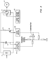
- Figure 3 shows the configuration in an example of the conventional regenerated power consumption method.
- the principal circuit of the inverter has converter (1) and inverter circuit (2).
- the 3-phase ac is converted to dc by converter (1), and it is then converted to 3-phase ac by inverter circuit (2).
- control is made by base driver (3) for induction motor control, so that the speed of induction motor (4) can be controlled.
- a regenerated power consumption circuit composed of resistor (5) and switch (6) formed of semiconductor elements in series is inserted in parallel into the aforementioned principal circuit.
- the dc voltage on the two ends of principal circuit capacitor (7) is detected by a voltage detector (8).
- the signal from said voltage detector (8) is input to hysteresis comparator (9).
- the magnitude of the dc voltage is the basis for ON/OFF control of base driver (10) of said switch (6). In this way, the regenerated power formed in the deceleration of induction motor (4) can be consumed by said resistor (5).
- Figure 4 shows the voltage waveform of the principal circuit in the aforementioned operation.
- the switch ON level and switch OFF level of said regenerated power consumption switch (6) are set at said comparator (9).
- the circuit is turned ON, the regenerated power is thus consumed; then as the dc voltage falls, the circuit is turned OFF.
- the elevator When the conventional regenerated power consumption method is used for an elevator, as shown in Figure 5, the elevator has an induction motor (4) as the power source, and has cage (12) and balance weight (13) loaded on winding drum (11). The velocity pattern for acceleration, deceleration, and constant velocity is generated by a control unit (14), and cage (12) may be stopped at any floor.
- the maximum load of the elevator depends on the number of passengers in the cage, etc. As there can be a significant number of passengers, there is a large regenerated power in the case of deceleration.
- the deceleration rate in the case of deceleration depends on the velocity pattern, and the regenerated power varies depending on the passenger number and deceleration rate.
- the regenerated power of the elevator depends significantly on the passenger number, and the operation status with deceleration or constant velocity. Consequently, for hysteresis comparator (9), the switching frequency and the ON/OFF ratio also depend significantly on the change in the regenerated power.
- a switch which allows high-speed switching operation up to several kHz must be used.
- the design of the circuit configuration becomes complicated. This is a disadvantage.
- Document GB-A-2167252 discloses a method of consuming regenerated power in an elevator system in which an elevator is driven with an induction motor, the motor being driven from a dc circuit via an inverter, and in which a resistor and a switch are connected in series to said dc circuit for consuming regenerated power, comprising detecting the voltage in the dc circuit and producing a detection signal.
- the purpose of this invention is to solve the aforementioned problems of the conventional methods by providing a regenerated power consumption method for elevators in which a switch with a low switching speed can be used, and the circuit configuration for the regenerated power consumption can be simplified.
- this invention provides a regenerated power consumption method in which the regenerated power generated when the elevator is driven with an induction motor is consumed by a serial circuit comprising a resistor and a switch and arranged in a dc circuit of the inverter.
- a serial circuit comprising a resistor and a switch and arranged in a dc circuit of the inverter.
- this regenerated power consumption method there is a software configuration filter which performs filtering treatment of the detected signal as the dc voltage of the aforementioned dc circuit exceeds the ON/OFF level of the aforementioned switch; if the aforementioned dc voltage rises or decreases, the aforementioned switch is ON/OFF controlled by the aforementioned filter.
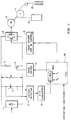
- Figure 1 shows the configuration of an embodiment of this invention.
- the configuration shown in this figure differs from that shown in Figures 3 and 5 in the following respects: the detected signal of voltage detector (8) is converted to a digital signal by an A/D converter (15).
- the converted value is filter-treated by a filter (16A) in a control unit (16) which comprises a CPU.
- the result of the filter treatment is taken as the ON/OFF control signal for base driver (10).
- V dc (n) V s - V dc (n - 1) (1 + T/dt) + V dc (n - 1)
- switching of filter (16A) from OFF to ON may be carried out in any of the following cases:
- controller (16) handles the output frequency and operation state of the inverter and the state of the input sequence.
- the maximum switching frequency is determined by the times T H , T L corresponding to the filter time constant.
- the switching output limited by the frequency determined by times T H , T L set in the software is generated, and the maximum switching frequency for the regenerated power consumption can be controlled by times T H , T L .
- the maximum switching frequency is 33.33 Hz, and the regenerated power consumption can be performed by using switch (6) with a switching speed appropriate to this frequency.
- the control of the regenerated power consumption is not limited to the case of deceleration of the elevator, it may also be performed corresponding to the variation in the regenerated power generated due to differences in the passenger number and the ascending descending state in the constant speed mode.
- the time constant of the filter can be set appropriately by setting the software, and filter (16A) itself can also be simplified by using the software configuration.
- switch (6) and resistor (5) for the regenerated power consumption are arranged as a single circuit.
- the aforementioned multiple circuits can perform ON operation in a parallel way when an overvoltage for dc voltage V dc is predicted; hence, overvoltage can be prevented.
- the insufficient voltage can be prevented by the ON/OFF control of one circuit.
- the regenerated power consumption is performed by detecting the dc voltage of the inverter, with the dc voltage of detection filter-treated by a filter with a software configuration; the maximum switching frequency of the switch is set by the time constant of the filter, the filter time constant is set corresponding to the switching speed of the switch, so as to ensure the regenerated power consumption.
- the circuit design and setting it is only necessary to change the time constant of the filter, which can be realized by making a simple change in the software.
- the conventional hysteresis comparator is not needed, and only the function of the elevator control equipment is used.
Landscapes
- Engineering & Computer Science (AREA)
- Automation & Control Theory (AREA)
- Elevator Control (AREA)
- Control Of Ac Motors In General (AREA)
- Stopping Of Electric Motors (AREA)
Claims (4)
- Verfahren zum Verbrauchen regenerierter Leistung in einem Aufzugsystem, in welchem ein Aufzug (12) von einem Asynchronmotor (4) angetrieben wird, der aus einem Gleichstromkreis über einen Wechselrichter (2) gespeist wird, wobei ein Widerstand (5) und ein Schalter (6) in Reihe zu dem Gleichstromkreis geschaltet sind, um regenerierte Leistung zu verbrauchen, und wobei die Spannung in dem Gleichstromkreis detektiert und ein Detektiersignal erzeugt wird, dadurch gekennzeichnet, daß das Detektiersignal einer Filterbehandlung mittels eines Softwarefilters (16A) unterzogen wird und der Schalter mit dem Ausgangssignal des Filters ein/aus-gesteuert wird, wobei das Filter derart arbeitet, daß es das Ein/Aus-Schalten des Schalters ansprechend auf Änderungen der detektierten Gleichspannung verzögert.
- Verfahren nach Anspruch 1, bei dem das Detektiersignal dann erzeugt wird, wenn die Gleichspannung den Einschalt- oder den Ausschaltpegel des Schalters (6) erreicht.
- Verfahren nach einem der vorhergehenden Ansprüche, bei dem die Filter-Zeitkonstante in Abhängigkeit von der Anzahl von Fahrgästen in dein Aufzug und/oder dem Bewegungszustand des Aufzugs eingestellt wird.
- Verfahren nach einem der vorhergehenden Ansprüche, bei dem an den Gleichstromkreis mehrere Widerstand-Schalter-Serienschaltungen angeschlossen sind, wobei die Schalter selektiv derart angesteuert werden, daß parallele Leistungsverbrauchskreise gebildet werden.
Priority Applications (3)
| Application Number | Priority Date | Filing Date | Title |
|---|---|---|---|
| JP3173580A JP2888670B2 (ja) | 1991-07-15 | 1991-07-15 | エレベータの回生電力消費方式 |
| DE1993609881 DE69309881T2 (de) | 1993-01-21 | 1993-01-21 | Rückführungssteuerung für einen Aufzugsinduktionsmotor |
| EP93300435A EP0607645B1 (de) | 1991-07-15 | 1993-01-21 | Rückführungssteuerung für einen Aufzugsinduktionsmotor |
Applications Claiming Priority (2)
| Application Number | Priority Date | Filing Date | Title |
|---|---|---|---|
| JP3173580A JP2888670B2 (ja) | 1991-07-15 | 1991-07-15 | エレベータの回生電力消費方式 |
| EP93300435A EP0607645B1 (de) | 1991-07-15 | 1993-01-21 | Rückführungssteuerung für einen Aufzugsinduktionsmotor |
Publications (2)
| Publication Number | Publication Date |
|---|---|
| EP0607645A1 EP0607645A1 (de) | 1994-07-27 |
| EP0607645B1 true EP0607645B1 (de) | 1997-04-16 |
Family
ID=26134149
Family Applications (1)
| Application Number | Title | Priority Date | Filing Date |
|---|---|---|---|
| EP93300435A Expired - Lifetime EP0607645B1 (de) | 1991-07-15 | 1993-01-21 | Rückführungssteuerung für einen Aufzugsinduktionsmotor |
Country Status (2)
| Country | Link |
|---|---|
| EP (1) | EP0607645B1 (de) |
| JP (1) | JP2888670B2 (de) |
Families Citing this family (5)
| Publication number | Priority date | Publication date | Assignee | Title |
|---|---|---|---|---|
| JP2001278554A (ja) * | 2000-03-29 | 2001-10-10 | Mitsubishi Electric Corp | エレベーターの電磁ブレーキ制御装置 |
| JP4544884B2 (ja) | 2004-03-18 | 2010-09-15 | 東芝エレベータ株式会社 | エレベータ制御装置 |
| JP4935397B2 (ja) * | 2007-02-09 | 2012-05-23 | 日産自動車株式会社 | 車両用駆動制御装置、車両用駆動制御方法及び過電圧保護回路 |
| JP5241367B2 (ja) * | 2008-07-30 | 2013-07-17 | 株式会社日立産機システム | 電動巻上機 |
| JP5941343B2 (ja) * | 2012-06-11 | 2016-06-29 | パナソニック ホームエレベーター株式会社 | エレベータ駆動制御装置 |
Family Cites Families (4)
| Publication number | Priority date | Publication date | Assignee | Title |
|---|---|---|---|---|
| JPS58154380A (ja) * | 1982-03-09 | 1983-09-13 | Mitsubishi Electric Corp | 交流エレベ−タの制御装置 |
| JPS6188774A (ja) * | 1984-10-05 | 1986-05-07 | Mitsubishi Electric Corp | エレベ−タの制御装置 |
| JPS63137597U (de) * | 1987-02-26 | 1988-09-09 | ||
| US4928052A (en) * | 1987-04-30 | 1990-05-22 | Fanuc Ltd. | Power supply regenerating circuit |
-
1991
- 1991-07-15 JP JP3173580A patent/JP2888670B2/ja not_active Expired - Fee Related
-
1993
- 1993-01-21 EP EP93300435A patent/EP0607645B1/de not_active Expired - Lifetime
Also Published As
| Publication number | Publication date |
|---|---|
| EP0607645A1 (de) | 1994-07-27 |
| JPH0517078A (ja) | 1993-01-26 |
| JP2888670B2 (ja) | 1999-05-10 |
Similar Documents
| Publication | Publication Date | Title |
|---|---|---|
| US5420491A (en) | Method for consuming regenerated power for elevators | |
| EP0278988B1 (de) | Wechselstrommotor-regelvorrichtung | |
| EP0303717B1 (de) | Antriebsregelsystem für einen elektrischen motor | |
| CN101068736B (zh) | 电梯装置 | |
| KR100361456B1 (ko) | 전기모터차량의브레이크제어장치및그의제어방법 | |
| EP1555744A2 (de) | Leistungswandler und Wechselrichter mit Wandlerschaltung | |
| JPH0789750B2 (ja) | クレ−ン用v/fインバ−タ制御方法 | |
| JPS6223387A (ja) | エレベ−タの制御装置 | |
| EP0607645B1 (de) | Rückführungssteuerung für einen Aufzugsinduktionsmotor | |
| KR840002352B1 (ko) | 교류엘리베이터의 제어장치 | |
| EP0144161B1 (de) | Steuer- und Regelsystem für einen Wechselstrom-Motor | |
| JPH0244755B2 (de) | ||
| JPS5844592B2 (ja) | エレベ−タセイギヨホウシキ | |
| KR100988137B1 (ko) | 인버터의 감속 제어 장치 및 방법 | |
| JPS6359945B2 (de) | ||
| JPH05213543A (ja) | エレベーターの制御装置 | |
| JP2938595B2 (ja) | エレベータの回生電力消費方法 | |
| JPS6351953B2 (de) | ||
| KR19980070091A (ko) | 엘리베이터의 도어 제어장치 및 방법 | |
| SU1444265A2 (ru) | Устройство дл задани режима движени шахтной подъемной установки | |
| JPH09255246A (ja) | 回生電力制御装置 | |
| JP2000166259A (ja) | 電動機駆動用インバータ装置の制御方法 | |
| JPS61162478A (ja) | エレベ−タ−の制御装置 | |
| JPS60204587A (ja) | エレベ−タ−非常時救出運転制御装置 | |
| JPH09219993A (ja) | 交流エレベータの制御装置 |
Legal Events
| Date | Code | Title | Description |
|---|---|---|---|
| PUAI | Public reference made under article 153(3) epc to a published international application that has entered the european phase |
Free format text: ORIGINAL CODE: 0009012 |
|
| AK | Designated contracting states |
Kind code of ref document: A1 Designated state(s): CH DE FR GB LI |
|
| 17P | Request for examination filed |
Effective date: 19940928 |
|
| 17Q | First examination report despatched |
Effective date: 19960206 |
|
| GRAG | Despatch of communication of intention to grant |
Free format text: ORIGINAL CODE: EPIDOS AGRA |
|
| GRAH | Despatch of communication of intention to grant a patent |
Free format text: ORIGINAL CODE: EPIDOS IGRA |
|
| GRAH | Despatch of communication of intention to grant a patent |
Free format text: ORIGINAL CODE: EPIDOS IGRA |
|
| GRAA | (expected) grant |
Free format text: ORIGINAL CODE: 0009210 |
|
| AK | Designated contracting states |
Kind code of ref document: B1 Designated state(s): CH DE FR GB LI |
|
| REG | Reference to a national code |
Ref country code: CH Ref legal event code: NV Representative=s name: E. BLUM & CO. PATENTANWAELTE Ref country code: CH Ref legal event code: EP |
|
| REF | Corresponds to: |
Ref document number: 69309881 Country of ref document: DE Date of ref document: 19970522 |
|
| ET | Fr: translation filed | ||
| PGFP | Annual fee paid to national office [announced via postgrant information from national office to epo] |
Ref country code: FR Payment date: 19971208 Year of fee payment: 6 |
|
| PGFP | Annual fee paid to national office [announced via postgrant information from national office to epo] |
Ref country code: GB Payment date: 19971218 Year of fee payment: 6 |
|
| PGFP | Annual fee paid to national office [announced via postgrant information from national office to epo] |
Ref country code: DE Payment date: 19971222 Year of fee payment: 6 |
|
| PGFP | Annual fee paid to national office [announced via postgrant information from national office to epo] |
Ref country code: CH Payment date: 19980106 Year of fee payment: 6 |
|
| PLBE | No opposition filed within time limit |
Free format text: ORIGINAL CODE: 0009261 |
|
| 26N | No opposition filed | ||
| PG25 | Lapsed in a contracting state [announced via postgrant information from national office to epo] |
Ref country code: GB Free format text: LAPSE BECAUSE OF NON-PAYMENT OF DUE FEES Effective date: 19990121 |
|
| PG25 | Lapsed in a contracting state [announced via postgrant information from national office to epo] |
Ref country code: LI Free format text: LAPSE BECAUSE OF NON-PAYMENT OF DUE FEES Effective date: 19990131 Ref country code: CH Free format text: LAPSE BECAUSE OF NON-PAYMENT OF DUE FEES Effective date: 19990131 |
|
| GBPC | Gb: european patent ceased through non-payment of renewal fee |
Effective date: 19990121 |
|
| REG | Reference to a national code |
Ref country code: CH Ref legal event code: PL |
|
| PG25 | Lapsed in a contracting state [announced via postgrant information from national office to epo] |
Ref country code: FR Free format text: LAPSE BECAUSE OF NON-PAYMENT OF DUE FEES Effective date: 19990930 |
|
| PG25 | Lapsed in a contracting state [announced via postgrant information from national office to epo] |
Ref country code: DE Free format text: LAPSE BECAUSE OF NON-PAYMENT OF DUE FEES Effective date: 19991103 |
|
| REG | Reference to a national code |
Ref country code: FR Ref legal event code: ST |