EP0607648B1 - Dämpfung der Rollbewegung bei schwimmenden Strukturen - Google Patents
Dämpfung der Rollbewegung bei schwimmenden Strukturen Download PDFInfo
- Publication number
- EP0607648B1 EP0607648B1 EP93305713A EP93305713A EP0607648B1 EP 0607648 B1 EP0607648 B1 EP 0607648B1 EP 93305713 A EP93305713 A EP 93305713A EP 93305713 A EP93305713 A EP 93305713A EP 0607648 B1 EP0607648 B1 EP 0607648B1
- Authority
- EP
- European Patent Office
- Prior art keywords
- ship
- rocking motion
- movable body
- linear motor
- floating structure
- Prior art date
- Legal status (The legal status is an assumption and is not a legal conclusion. Google has not performed a legal analysis and makes no representation as to the accuracy of the status listed.)
- Expired - Lifetime
Links
- 230000033001 locomotion Effects 0.000 title claims description 34
- 238000007667 floating Methods 0.000 title claims description 21
- 239000007787 solid Substances 0.000 claims description 16
- 238000005096 rolling process Methods 0.000 description 23
- 238000010276 construction Methods 0.000 description 14
- 239000003381 stabilizer Substances 0.000 description 8
- 238000006073 displacement reaction Methods 0.000 description 7
- XLYOFNOQVPJJNP-UHFFFAOYSA-N water Substances O XLYOFNOQVPJJNP-UHFFFAOYSA-N 0.000 description 7
- 230000001133 acceleration Effects 0.000 description 5
- 230000000694 effects Effects 0.000 description 5
- 230000004044 response Effects 0.000 description 5
- 230000002411 adverse Effects 0.000 description 3
- 230000005484 gravity Effects 0.000 description 2
- 230000007246 mechanism Effects 0.000 description 2
- 230000001360 synchronised effect Effects 0.000 description 2
- 238000004804 winding Methods 0.000 description 2
- 230000002146 bilateral effect Effects 0.000 description 1
- 238000006243 chemical reaction Methods 0.000 description 1
- 230000008878 coupling Effects 0.000 description 1
- 238000010168 coupling process Methods 0.000 description 1
- 238000005859 coupling reaction Methods 0.000 description 1
- 238000010586 diagram Methods 0.000 description 1
- 230000008030 elimination Effects 0.000 description 1
- 238000003379 elimination reaction Methods 0.000 description 1
- 230000007613 environmental effect Effects 0.000 description 1
- 230000005284 excitation Effects 0.000 description 1
- 238000009434 installation Methods 0.000 description 1
- 238000012423 maintenance Methods 0.000 description 1
- 230000009347 mechanical transmission Effects 0.000 description 1
- 238000000034 method Methods 0.000 description 1
- 230000004048 modification Effects 0.000 description 1
- 238000012986 modification Methods 0.000 description 1
- 230000010355 oscillation Effects 0.000 description 1
- 230000008569 process Effects 0.000 description 1
- 230000009467 reduction Effects 0.000 description 1
- 239000011435 rock Substances 0.000 description 1
- 239000003643 water by type Substances 0.000 description 1
Images




Classifications
-
- B—PERFORMING OPERATIONS; TRANSPORTING
- B63—SHIPS OR OTHER WATERBORNE VESSELS; RELATED EQUIPMENT
- B63B—SHIPS OR OTHER WATERBORNE VESSELS; EQUIPMENT FOR SHIPPING
- B63B39/00—Equipment to decrease pitch, roll, or like unwanted vessel movements; Apparatus for indicating vessel attitude
- B63B39/02—Equipment to decrease pitch, roll, or like unwanted vessel movements; Apparatus for indicating vessel attitude to decrease vessel movements by displacement of masses
Definitions
- the present invention relates to marine floating structures, such as ships or barges and is concerned with apparatus for reducing or suppressing rocking motion, such as rolling and pitching, of such structures.
- FIG. 1 is a schematic view of an anti-rolling tank which is used to suppress rolling of a ship.
- a U-shaped water tank c whose upper ends communicate through an air pipe b, is arranged in a main hull of a ship on a deck above the centre of gravity of the hull. It is designed such that in response to rolling of the hull a, the water d in the tank c is caused to effect passive resonance which lags the rolling in phase by 90°.
- FIG. 2 is a schematic view of a fin stabilizer which comprises movable fins f which are driven by drives e and which are attached to the submerged bilge of the main hull of a ship substantially at the mid-point thereof in a fore-and-aft direction.
- the angle of rolling, the angular velocity and the angular acceleration of the main hull a are detected by a sensor g and the angle of elevation of each fin f is actively varied in response to the detected values so that the rolling of the main hull a is suppressed by dynamic lift produced on the fins f by the velocity of the ship through the water.
- FIG. 3 An anti-rocking system using a solid mass has also been proposed, and such a system is shown schematically in Figure 3.
- This includes a base h with rails i mounted on the bottom, deck or the like of the main hull a of a ship and a weight k constituting a solid mass rides on wheels j on the rails i.
- a lead-screw 1 extends through and is in threaded engagement with the weight k and is supported by spaced bearings m.
- One end of the lead-screw 1 is connected through a coupling p to a reduction gear n and a motor o.
- the motor n When the main hull a rocks, the motor n is rotated in a clockwise or anticlockwise direction so that the weight k is displaced in a direction opposite to that of the external force acting on the hull a so as to reduce the rolling motion of the hull a.
- Anti-rolling tanks have the following problems:
- a drive In the case of anti-rocking systems utilizing solid mass, a drive includes a rotating body so that in order to linearly drive the driven body linearly, an auxiliary system comprising gears and a screw (or a linkage) is required.
- an auxiliary system comprising gears and a screw (or a linkage) is required.
- the construction is complicated and system failure frequently occurs and consequently maintenance becomes problematic.
- the weight of the system is very high.
- GB-A-2213789 on which the precharacterising portion of Claim 1 is based, discloses a marine stabiliser including a moving mass which forms the whole structure of a linear motor.
- the reaction rail or stator of the motor is fixedly secured to the ship.
- the mass moves on a rail which extends across or along the ship.
- the linear motor is controlled in response to signals produced by accelerometers or the like.
- a floating marine structure such as a ship, includes apparatus for reducing rocking motion thereof, the apparatus including a solid mass, a linear motor to move the solid mass relative to the floating structure, the linear motor including a stator fixedly secured to the floating structure and a movable member which is constituted by the solid mass, a sensor for detecting rocking motion of the floating structure and a controller for delivering a phase-controlled driving command signal to the linear motor is characterised in that the movable member and the stator are in the form of concentric arcs.
- rocking motion of the marine floating structure When rocking motion of the marine floating structure is detected by the rocking motion sensor, it produces a signal which is phase-controlled by the controller and is supplied as an output to the linear motor.
- the movable member In response to the received signal, the movable member is forced to move along an arcuate path in the direction reducing the rocking motion so that the movable member of the linear motor acts as a solid mass to reduce rocking motion of the marine floating structure.
- the movable body is forced to swing like a pendulum, thereby suppressing the rocking motion of a ship.
- Synchronizing the natural period of the movable body with that of the hull enables the movable body to act as passive means to reduce any rocking motion of the ship without operating the variable drive power supply at the synchronous or resonance point of the rocking.
- the apparatus for reducing rocking motion dispenses with gears, screws and other mechanical transmission components. Accordingly, the apparatus can respond immediately to rocking motion of the structure to reduce that rocking motion. Since a solid mass is used, as opposed to the water of anti-rolling tank systems, the installation space required is considerably reduced. In the case of ships, as opposed to other marine floating structures, the apparatus can be disposed in the main hull. As a result, steering operation of the ship is improved, the ability to maintain the ship in an upright position is enhanced and the space within the main hull is used effectively. In calm seas the solid mass constituted by the movable member can be moved appropriately to prevent the marine floating structure from listing.
- the apparatus for reducing rocking motion can inherently be of compact and inexpensive construction. Due to the use of a linear motor, friction is minimised and the solid mass can be displaced by a relatively low-power drive so that running costs are also reduced. If the number, position and orientation of linear motors is selected appropriately rocking motion in all directions of the marine floating structure can be reduced and thus the structure satisfactorily stabilized. Due to the elimination of gears and other mechanical linkages the noise produced during operation is substantially reduced.
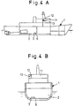
- the marine floating structure is a ship generally indicated by reference numeral 1.
- a base 3 is mounted on the bottom floor of the engine room 2 and two parallel guide rails 7 are laid on the base 3.
- the linear motor 6 comprises a driven or movable means or body 4 and a stator means or body 5.
- the movable body 4 rides on wheels 8 on the rails 7 while the stator body 5 is securely arranged between the rails 7 and parallel therewith such that the top of the stator body 5 is spaced from the bottom of the movable body 4.
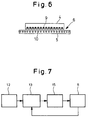
- the stator body 5 is electrically connected to an excitation power supply (not shown) and the movable body 4 is electrically connected to a variable drive power supply 15 (see Figure 7) so that when electric current is supplied to the movable body 4, a dielectric electromotive force is produced between the bodies 4 and 5 and consequently the movable body 4 is forced to move linearly as a solid mass along the stator body 5.
- the movable body 4 of the linear motor 6 consists of a primary core with three-phase windings 9 and the stator body 5 consists of a secondary core with squirrel-cage windings 10.
- the movable body 4 is located on one side of the stator body 5.
- a rocking-motion sensor 12 and a controller 13 are located at any suitable position in the ship, typically substantially higher than the linear motor, in this case in the wheelhouse 11.
- the variable drive power supply 15 of the movable body 4 is energized by a control signal generated and delivered by the controller 13 in response to a signal from the rocking-motion sensor 12 so that displacement of the movable body 4 is controlled in relation to the rocking motion of the ship 1 and consequently the energy of rocking motion of the ship 1 is consumed or absorbed.
- the controller 13 processes the rocking-motion signal from the rocking-motion sensor 12 and delivers to the power supply 15 a phase and displacement signal which lags the rocking motion of the ship 1 in phase by 90°.
- the displacement signal applied to the movable body 4 is also fed back to the controller 13.
- the rocking-motion sensor 12 comprises an acceleration sensor and the acceleration is integrated twice in the controller 13 to generate the displacement signal, but it is possible to integrate the degree of acceleration only once to generate a velocity signal which in turn is converted into a reversed signal to be applied to the movable body 4 as a displacement signal.
- the flow of electric current through the primary core or movable body 4 of the linear motor 6 causes a dielectric electromotive force to be produced between the movable body 4 and the stator body 5 so that the movable body 4 is forced to move along the guide rails 7. Therefore, when rocking motion of the ship 1 is detected by the rocking-motion sensor 12, a phase-controlled signal based on the signal from the sensor 12 is transmitted from the controller 13 to the variable drive power supply of the movable body 4 so that the movable body 4 is forced to move in a direction to reduce the rocking motion in relation to the external force acting on the ship 1 and the movable body 4 functions as solid mass to immediately suppress the rocking motion of the ship 1.
- the movement of the movable body 4 can be controlled by phase-controlling the multi-phase alternating current and the velocity and acceleration can be controlled by changing the frequency.
- the ship's rocking motion can thus be reduced by a mechanism of simple construction without using gears, lead screws and the like.
- the second construction shown in Figures 8A and 8B which is also not in accordance with the invention, is similar to the first construction shown in Figure 5 except that the linear motor 6 is in the form of cylinder. More specifically, the movable body 4 constituting the solid mass is a hollow cylinder through which a rod-like stator body 5 extends for movement of the movable body 4. Opposite ends of the stator body 5 are secured in position with respect to the base 3. This construction operates in a manner similar to the first construction.
- Figures 9 and 10 illustrate first and second embodiments of apparatus for reducing rocking motion in accordance with the invention which are modifications of the first and second constructions described above, respectively.
- the movable body 4 and the stator body 5 of the linear motor 6 are in the form of arcs and arranged concentrically.
- the movable body 4 is supported by support rollers 14 which are spaced apart along the length of the stator body 5.
- the cylindrical linear motor 6 is constructed again in the form of an arc.
- the movable body 4 is forced to swing like a pendulum (in single harmonic oscillation), thereby suppressing the rocking motion of a ship.
- Synchronizing the natural period of the movable body 4 with that of the hull enables the movable body 4 to act as passive means to reduce any rocking motion of the ship without operating the variable drive power supply at the synchronous or resonance point of the rocking.
- the apparatus is arranged across the width of the ship so as to reduce rolling of the ship; but when the apparatus is arranged along the length of the ship, pitching of the ship can be reduced.
- one apparatus is arranged in the widthwise direction of a ship while another is arranged in the lengthwise direction both rolling and pitching can be reduced.
- one-sided or unilateral type linear motors are used, but it is to be understood that the present invention may utilise a two-sided or bilateral type linear motor.
- two movable bodies 4 can be arranged on opposite sides of the stator body 5.
- the movable body 4 may consist of a secondary core while the stator body 5 is a primary core.
- the rocking-motion reducing apparatus is disposed on a ship; but it is to be understood that the apparatus may be mounted in any marine floating structures.
Landscapes
- Chemical & Material Sciences (AREA)
- Engineering & Computer Science (AREA)
- Combustion & Propulsion (AREA)
- Mechanical Engineering (AREA)
- Ocean & Marine Engineering (AREA)
- Vibration Prevention Devices (AREA)
Claims (2)
- Schwimmende Struktur, etwa ein Schiff (1), umfassend eine Vorrichtung (6) zum Verringern ihrer Rollbewegung, wobei die Vorrichtung eine feste Masse (4), einen zum Bewegen der festen Masse relativ zu der Schwimmenden Struktur (1) dienenden Linearmotor, der einen fest mit der Schwimmenden Struktur verbundenen Stator (5) und ein bewegliches Bauteil umfaßt, das durch die feste Masse (4) gebildet wird, einen Sensor (12) zum Feststellen der Rollbewegung der Schwimmenden Struktur und eine ein phasengesteuertes Antriebsbefehlssignal an den Linearmotor (6) abgebende Steuerung (13), dadurch gekennzeichnet, daß das bewegliche Bauteil (4) und der Stator (5) die Form von konzentrischen Bögen haben.
- Struktur nach Anspruch 1, dadurch gekennzeichnet, daß das bewegliche Bauteil (4) die Form eines Hohlzylinders aufweist, daß der Stator die Form einer sich durch das bewegliche Bauteil erstreckenden Stange (5) aufweist, und daß die Enden der Stange (5) fest mit der Schwimmenden Struktur verbunden sind.
Applications Claiming Priority (2)
| Application Number | Priority Date | Filing Date | Title |
|---|---|---|---|
| JP4354877A JPH06183394A (ja) | 1992-12-18 | 1992-12-18 | 海洋構造物の減揺装置 |
| JP354877/92 | 1992-12-18 |
Publications (2)
| Publication Number | Publication Date |
|---|---|
| EP0607648A1 EP0607648A1 (de) | 1994-07-27 |
| EP0607648B1 true EP0607648B1 (de) | 1997-10-22 |
Family
ID=18440511
Family Applications (1)
| Application Number | Title | Priority Date | Filing Date |
|---|---|---|---|
| EP93305713A Expired - Lifetime EP0607648B1 (de) | 1992-12-18 | 1993-07-20 | Dämpfung der Rollbewegung bei schwimmenden Strukturen |
Country Status (5)
| Country | Link |
|---|---|
| US (1) | US5433162A (de) |
| EP (1) | EP0607648B1 (de) |
| JP (1) | JPH06183394A (de) |
| KR (1) | KR970007224B1 (de) |
| DE (1) | DE69314765T2 (de) |
Families Citing this family (24)
| Publication number | Priority date | Publication date | Assignee | Title |
|---|---|---|---|---|
| US5622130A (en) * | 1995-05-22 | 1997-04-22 | Dyna-Yacht, Inc. | Heel control system for sailing yachts and sailing yacht hull |
| JP3324353B2 (ja) * | 1995-08-18 | 2002-09-17 | 京都大学長 | 振り子構造物 |
| NL1011728C2 (nl) * | 1999-04-02 | 2000-10-03 | Ravestein Container Pontoon B | Inrichting voor het in balans brengen van een vaartuig. |
| FR2802504B1 (fr) * | 1999-12-20 | 2002-03-01 | Technicatome | Dispositif ameliore d'equilibrage d'un navire notamment en roulis |
| KR100737679B1 (ko) * | 2002-12-30 | 2007-07-09 | 현대중공업 주식회사 | 횡요감쇄 탱크의 고유주기 변환장치 |
| TWM283013U (en) * | 2005-05-17 | 2005-12-11 | Wei-Liang Lee | Tumbler base for structure |
| KR100834289B1 (ko) * | 2007-02-08 | 2008-05-30 | 현대중공업 주식회사 | 발라스트 탱크 없는 선박 |
| CN101918271B (zh) * | 2007-10-11 | 2013-09-11 | 伊特雷科公司 | 带横摇阻尼机构的船 |
| KR101015167B1 (ko) * | 2008-09-16 | 2011-02-17 | 에스티엑스조선해양 주식회사 | 이동식 발라스트 탱크를 가지는 바지선 및 운반물의 이송에따른 바지선의 발라스팅 방법 |
| CN102079364B (zh) * | 2009-11-27 | 2013-04-10 | 三一电气有限责任公司 | 风机安装船及其重心调节装置 |
| KR101667269B1 (ko) * | 2010-07-12 | 2016-10-19 | 대우조선해양 주식회사 | 무인 잠수정의 자동 자세 제어장치 |
| LU91809B1 (en) * | 2011-04-20 | 2012-10-22 | Vincent De Troz | Mobile ballast device |
| KR101454387B1 (ko) * | 2013-01-17 | 2014-10-24 | 삼성중공업 주식회사 | 횡동요 저감장치 |
| KR101588872B1 (ko) * | 2014-01-08 | 2016-01-26 | 삼성중공업 주식회사 | 진수용 선박 |
| JP6276627B2 (ja) * | 2014-03-28 | 2018-02-07 | 株式会社Ihiインフラシステム | 制振装置 |
| KR101485080B1 (ko) * | 2014-06-25 | 2015-01-21 | 엘아이지넥스원 주식회사 | 자세 제어 장치를 구비하는 수중 운동체 |
| DE102014215982A1 (de) | 2014-08-12 | 2016-02-18 | Robert Bosch Gmbh | Vorrichtung für ein Wasserfahrzeug, Wasserfahrzeug |
| DE102014215983A1 (de) | 2014-08-12 | 2016-02-18 | Robert Bosch Gmbh | Stabilisatorvorrichtung für ein Wasserfahrzeug, insbesondere für ein motorbetriebenes Wasserfahrzeug |
| KR101539066B1 (ko) * | 2014-09-30 | 2015-07-22 | 엘아이지넥스원 주식회사 | 수중 운동체의 자세 제어 장치 및 그 방법 |
| JP6297013B2 (ja) * | 2015-08-03 | 2018-03-20 | 株式会社Ihiインフラシステム | 減揺装置 |
| JP7129278B2 (ja) * | 2018-08-27 | 2022-09-01 | 株式会社Ihiインフラシステム | 制振装置 |
| CN110525585B (zh) * | 2019-09-25 | 2021-03-30 | 哈尔滨工程大学 | 一种强迫横摇减摇鳍实体性能测试装置 |
| US11427287B1 (en) * | 2020-06-16 | 2022-08-30 | Elliott B. Dollar | Weight distribution system and method of modifying a wake |
| EP4292918A1 (de) | 2022-06-17 | 2023-12-20 | GE Energy Power Conversion Technology Ltd | Elektrische stabilisatoren |
Family Cites Families (7)
| Publication number | Priority date | Publication date | Assignee | Title |
|---|---|---|---|---|
| US57834A (en) * | 1866-09-04 | Improved apparatus for trimming ships | ||
| DE1531651A1 (de) * | 1967-08-12 | 1969-12-11 | Siemens Ag | Anordnung zur Schiffsstabilisierung mit einem verschiebbaren Wagen |
| US3809000A (en) * | 1971-08-04 | 1974-05-07 | Secretary Trade Ind Brit | Passive roll stabilisers |
| JPS4919514A (de) * | 1972-06-15 | 1974-02-21 | ||
| US4793263A (en) * | 1986-08-01 | 1988-12-27 | The Boeing Company | Integrated linear synchronous unipolar motor with controlled permanent magnet bias |
| GB2213789A (en) * | 1988-01-15 | 1989-08-23 | Yarrow Shipbuilders Limited | Ship stabiliser |
| JP2668990B2 (ja) * | 1988-10-06 | 1997-10-27 | 石川島播磨重工業株式会社 | 構造物制振装置 |
-
1992
- 1992-12-18 JP JP4354877A patent/JPH06183394A/ja active Pending
-
1993
- 1993-06-28 US US08/082,497 patent/US5433162A/en not_active Expired - Lifetime
- 1993-07-07 KR KR1019930012689A patent/KR970007224B1/ko not_active Expired - Lifetime
- 1993-07-20 DE DE69314765T patent/DE69314765T2/de not_active Expired - Lifetime
- 1993-07-20 EP EP93305713A patent/EP0607648B1/de not_active Expired - Lifetime
Also Published As
| Publication number | Publication date |
|---|---|
| JPH06183394A (ja) | 1994-07-05 |
| KR940014081A (ko) | 1994-07-16 |
| KR970007224B1 (ko) | 1997-05-07 |
| US5433162A (en) | 1995-07-18 |
| DE69314765T2 (de) | 1998-05-28 |
| EP0607648A1 (de) | 1994-07-27 |
| DE69314765D1 (de) | 1997-11-27 |
Similar Documents
| Publication | Publication Date | Title |
|---|---|---|
| US5433162A (en) | Apparatus for reducing rocking motion of marine floating structure | |
| US9038554B2 (en) | Mobile ballast device | |
| US5511504A (en) | Computer controlled fins for improving seakeeping in marine vessels | |
| CN108313232B (zh) | 基于二维矢量推进器和移动重物的组合式船舶减摇装置 | |
| US3468282A (en) | Continuous operation motor tilt control mechanism | |
| US5622130A (en) | Heel control system for sailing yachts and sailing yacht hull | |
| JP2003520725A (ja) | 能動力反動システム及び受動減衰を有する係船システム | |
| CN109305309B (zh) | 一种多功能可伸缩式船舶矢量螺旋减摇臂 | |
| KR101709126B1 (ko) | 부유식 해상용 풍력발전기의 자세안정화 제어방법 | |
| EP1772372B1 (de) | System zur Verminderung einer Schiffschlingerbewegung | |
| CN111301626A (zh) | 船舶直翼减摇系统 | |
| US20160230739A1 (en) | Semisubmersible platform equipped with an angular amplification system | |
| KR20120112891A (ko) | 질량 이동형 횡동요 저감장치 | |
| KR20010089684A (ko) | 반잠수가능한 중량 화물선 | |
| CN114179961A (zh) | 姿态自适应式水面双体无人平台 | |
| JP2012096774A (ja) | 減揺機能を備えたトリマラン船 | |
| CN116902129A (zh) | 一种对波浪主动补偿的双体船及控制方法 | |
| AU2004270614C1 (en) | Two degree of freedom rudder/stabilizer for waterborne vessels | |
| US4304190A (en) | Ferry boat | |
| KR100545914B1 (ko) | 감쇠력 자동조절기능이 있는 질량이동형 횡동요 감쇠장치 | |
| KR20100055628A (ko) | 선박 및 해양구조물의 가변형 빌지 킬과 이를 이용한 횡요운동 제어방법 | |
| JP7352522B2 (ja) | 水上移動体 | |
| KR20230156309A (ko) | 선박 진동 댐퍼 시스템 | |
| JP3517895B2 (ja) | 海洋構造物の減揺装置 | |
| JPS59190083A (ja) | 推力発生装置 |
Legal Events
| Date | Code | Title | Description |
|---|---|---|---|
| PUAI | Public reference made under article 153(3) epc to a published international application that has entered the european phase |
Free format text: ORIGINAL CODE: 0009012 |
|
| AK | Designated contracting states |
Kind code of ref document: A1 Designated state(s): DE FR GB |
|
| 17P | Request for examination filed |
Effective date: 19940801 |
|
| 17Q | First examination report despatched |
Effective date: 19950710 |
|
| GRAG | Despatch of communication of intention to grant |
Free format text: ORIGINAL CODE: EPIDOS AGRA |
|
| GRAH | Despatch of communication of intention to grant a patent |
Free format text: ORIGINAL CODE: EPIDOS IGRA |
|
| GRAH | Despatch of communication of intention to grant a patent |
Free format text: ORIGINAL CODE: EPIDOS IGRA |
|
| GRAA | (expected) grant |
Free format text: ORIGINAL CODE: 0009210 |
|
| AK | Designated contracting states |
Kind code of ref document: B1 Designated state(s): DE FR GB |
|
| REF | Corresponds to: |
Ref document number: 69314765 Country of ref document: DE Date of ref document: 19971127 |
|
| ET | Fr: translation filed | ||
| PLBE | No opposition filed within time limit |
Free format text: ORIGINAL CODE: 0009261 |
|
| STAA | Information on the status of an ep patent application or granted ep patent |
Free format text: STATUS: NO OPPOSITION FILED WITHIN TIME LIMIT |
|
| 26N | No opposition filed | ||
| REG | Reference to a national code |
Ref country code: GB Ref legal event code: IF02 |
|
| PGFP | Annual fee paid to national office [announced via postgrant information from national office to epo] |
Ref country code: GB Payment date: 20120718 Year of fee payment: 20 |
|
| PGFP | Annual fee paid to national office [announced via postgrant information from national office to epo] |
Ref country code: FR Payment date: 20120719 Year of fee payment: 20 Ref country code: DE Payment date: 20120718 Year of fee payment: 20 |
|
| REG | Reference to a national code |
Ref country code: DE Ref legal event code: R071 Ref document number: 69314765 Country of ref document: DE |
|
| REG | Reference to a national code |
Ref country code: DE Ref legal event code: R071 Ref document number: 69314765 Country of ref document: DE |
|
| REG | Reference to a national code |
Ref country code: GB Ref legal event code: PE20 Expiry date: 20130719 |
|
| PG25 | Lapsed in a contracting state [announced via postgrant information from national office to epo] |
Ref country code: DE Free format text: LAPSE BECAUSE OF EXPIRATION OF PROTECTION Effective date: 20130723 |
|
| PG25 | Lapsed in a contracting state [announced via postgrant information from national office to epo] |
Ref country code: GB Free format text: LAPSE BECAUSE OF EXPIRATION OF PROTECTION Effective date: 20130719 |