EP0607708A1 - Vanne d'arrêt - Google Patents
Vanne d'arrêt Download PDFInfo
- Publication number
- EP0607708A1 EP0607708A1 EP93310650A EP93310650A EP0607708A1 EP 0607708 A1 EP0607708 A1 EP 0607708A1 EP 93310650 A EP93310650 A EP 93310650A EP 93310650 A EP93310650 A EP 93310650A EP 0607708 A1 EP0607708 A1 EP 0607708A1
- Authority
- EP
- European Patent Office
- Prior art keywords
- housing
- opening
- valve
- valve member
- stem
- Prior art date
- Legal status (The legal status is an assumption and is not a legal conclusion. Google has not performed a legal analysis and makes no representation as to the accuracy of the status listed.)
- Withdrawn
Links
- 230000002093 peripheral effect Effects 0.000 claims abstract description 22
- 230000000694 effects Effects 0.000 claims abstract description 7
- 238000007789 sealing Methods 0.000 claims description 38
- 230000013011 mating Effects 0.000 claims description 11
- 239000000463 material Substances 0.000 claims description 4
- 239000013536 elastomeric material Substances 0.000 claims description 3
- 239000000853 adhesive Substances 0.000 claims description 2
- 230000001070 adhesive effect Effects 0.000 claims description 2
- 229920001971 elastomer Polymers 0.000 abstract description 15
- 238000000576 coating method Methods 0.000 abstract description 13
- 239000000806 elastomer Substances 0.000 abstract description 13
- 239000011248 coating agent Substances 0.000 abstract description 12
- 239000012530 fluid Substances 0.000 abstract description 11
- 238000009434 installation Methods 0.000 abstract description 5
- 238000005299 abrasion Methods 0.000 abstract description 2
- 238000003780 insertion Methods 0.000 abstract description 2
- 230000037431 insertion Effects 0.000 abstract description 2
- 230000007246 mechanism Effects 0.000 abstract description 2
- 238000000034 method Methods 0.000 description 6
- XLYOFNOQVPJJNP-UHFFFAOYSA-N water Substances O XLYOFNOQVPJJNP-UHFFFAOYSA-N 0.000 description 6
- 239000004593 Epoxy Substances 0.000 description 4
- 230000006378 damage Effects 0.000 description 4
- 238000009826 distribution Methods 0.000 description 4
- 238000004519 manufacturing process Methods 0.000 description 4
- 230000002028 premature Effects 0.000 description 4
- -1 steam Substances 0.000 description 4
- 238000005266 casting Methods 0.000 description 3
- 230000007797 corrosion Effects 0.000 description 3
- 238000005260 corrosion Methods 0.000 description 3
- 230000006866 deterioration Effects 0.000 description 3
- 239000011253 protective coating Substances 0.000 description 3
- 239000011324 bead Substances 0.000 description 2
- 150000001875 compounds Chemical class 0.000 description 2
- 239000003112 inhibitor Substances 0.000 description 2
- 239000010410 layer Substances 0.000 description 2
- 238000003754 machining Methods 0.000 description 2
- 230000014759 maintenance of location Effects 0.000 description 2
- 230000001681 protective effect Effects 0.000 description 2
- 230000008439 repair process Effects 0.000 description 2
- 230000000630 rising effect Effects 0.000 description 2
- 239000000126 substance Substances 0.000 description 2
- 210000002105 tongue Anatomy 0.000 description 2
- 229910001369 Brass Inorganic materials 0.000 description 1
- 229910001208 Crucible steel Inorganic materials 0.000 description 1
- 229920000459 Nitrile rubber Polymers 0.000 description 1
- 239000004698 Polyethylene Substances 0.000 description 1
- 239000004743 Polypropylene Substances 0.000 description 1
- 208000027418 Wounds and injury Diseases 0.000 description 1
- 230000009471 action Effects 0.000 description 1
- 230000001154 acute effect Effects 0.000 description 1
- 239000010951 brass Substances 0.000 description 1
- 238000010073 coating (rubber) Methods 0.000 description 1
- 239000011247 coating layer Substances 0.000 description 1
- 230000000295 complement effect Effects 0.000 description 1
- 230000008030 elimination Effects 0.000 description 1
- 238000003379 elimination reaction Methods 0.000 description 1
- 230000002708 enhancing effect Effects 0.000 description 1
- 229920002457 flexible plastic Polymers 0.000 description 1
- 208000014674 injury Diseases 0.000 description 1
- 239000002184 metal Substances 0.000 description 1
- 229910052751 metal Inorganic materials 0.000 description 1
- 150000002739 metals Chemical class 0.000 description 1
- 238000012986 modification Methods 0.000 description 1
- 230000004048 modification Effects 0.000 description 1
- 150000002825 nitriles Chemical class 0.000 description 1
- 229920000573 polyethylene Polymers 0.000 description 1
- 229920001155 polypropylene Polymers 0.000 description 1
- 229920001343 polytetrafluoroethylene Polymers 0.000 description 1
- 239000004810 polytetrafluoroethylene Substances 0.000 description 1
- 229920002635 polyurethane Polymers 0.000 description 1
- 239000004814 polyurethane Substances 0.000 description 1
- 230000002035 prolonged effect Effects 0.000 description 1
- 230000000717 retained effect Effects 0.000 description 1
- 239000003566 sealing material Substances 0.000 description 1
- 239000002351 wastewater Substances 0.000 description 1
Images


Classifications
-
- F—MECHANICAL ENGINEERING; LIGHTING; HEATING; WEAPONS; BLASTING
- F16—ENGINEERING ELEMENTS AND UNITS; GENERAL MEASURES FOR PRODUCING AND MAINTAINING EFFECTIVE FUNCTIONING OF MACHINES OR INSTALLATIONS; THERMAL INSULATION IN GENERAL
- F16K—VALVES; TAPS; COCKS; ACTUATING-FLOATS; DEVICES FOR VENTING OR AERATING
- F16K27/00—Construction of housing; Use of materials therefor
- F16K27/08—Guiding yokes for spindles; Means for closing housings; Dust caps, e.g. for tyre valves
-
- F—MECHANICAL ENGINEERING; LIGHTING; HEATING; WEAPONS; BLASTING
- F16—ENGINEERING ELEMENTS AND UNITS; GENERAL MEASURES FOR PRODUCING AND MAINTAINING EFFECTIVE FUNCTIONING OF MACHINES OR INSTALLATIONS; THERMAL INSULATION IN GENERAL
- F16K—VALVES; TAPS; COCKS; ACTUATING-FLOATS; DEVICES FOR VENTING OR AERATING
- F16K27/00—Construction of housing; Use of materials therefor
- F16K27/04—Construction of housing; Use of materials therefor of sliding valves
- F16K27/044—Construction of housing; Use of materials therefor of sliding valves slide valves with flat obturating members
Definitions
- the present invention relates to gate valve structures used primarily in large mains carrying fluid under high pressure such as water mains in city and country water distribution systems. It will be apparent, however, to those skilled in this art, that while the design considerations giving rise to the present invention are directed primarily to problems resulting from high pressure water distribution systems, the valve of the present invention can be successfully utilized in a wide range of water main sizes and in other fluid distribution systems such as fire protection and waste water systems as well as chemical, steam, gas, oil or the like systems, wherein the fluid is under varying pressures from low to high pressure and may contain corrosive chemicals.
- a flow control device comprising: a housing having a longitudinal axis and, at one portion, a through passage, a valve member mounted for movement in said housing relative to said passage to control flow through said passage, said housing having, at another portion, an opening receiving operating means for effecting movement of said valve member, said housing having, adjacent said opening, an internal lip which surrounds said longitudinal axis and an internal sealing surface adjacent said lip also surrounding said longitudinal axis and extending at an angle relative to said longitudinal axis, closing means for said opening, said closing means having a first peripheral surface for engaging said internal lip and a second peripheral portion supporting a resiliently compressible sealing member so as to sealingly engage said internal sealing surface when said closing means is positioned to close said opening.
- a preferred embodiment of the invention may comprise any of the following features:- said closing means has aperture means for receiving and supporting said operating means for rotation relative to said aperture means about said longitudinal axis when installed in said opening, said closing means including a shoulders portion extending at least partially about said aperture means and extending from adjacent said first peripheral surface through and beyond said opening of said housing, when said closing means is positioned to close said opening, said shoulder portion having a peripheral external surface provided with spaced apart, radially projecting lug members, said closing means including a retaining ring having spaced apart radially inwardly projecting lug members, each for engaging a said lug member of said shoulder portion upon relative rotation between said retaining ring and said shoulder portion to thereby restrain axial movement of said closing means toward said opening.
- said respective lugs members are 180° apart on said shoulder portion and on said retaining ring.
- said retaining ring is provided with an insulating coating.
- said lug members of said shoulder portion and said retaining ring each include complimentary sloping surfaces to facilitate interengagement between a said lug member of said retaining ring and a said lug member of said shoulder portion.
- a portion of said shoulder portion and a portion of said retaining ring are shaped to provide a recess when said respective lug members are interengaged for receiving an adhesive material therebetween.
- said aperture means includes, in axial alignment from one end of said closing means to the opposite end, a cavity having an interior threaded portion, a bore and a counter bore, a retainer bushing having an externally threaded surface for cooperation with said threaded portion of said cavity and a central bore
- said operating means comprises a stem having a first portion insertable into said central bore of said retainer bushing, a collar for reception in said bore of said aperture means and a main portion extending from said collar through said counter bore to said valve member, said collar having a radial dimension greater than said central bore and said counter bore.
- said retainer bushing is provided with a recess for facing said bore of said closing means for receiving a friction washer in said recess so as to engage said collar of said stem.
- another friction washer is provided on a side of said collar opposite said side facing said recess of said retainer bushing.
- said central bore of said retainer bushing and said first portion of said stem includes sealing means therebetween. Seal means are provided between said main portion of said stem and said counter bore. sealing means are provided between said cavity and said retaining bushing at a position spaced axially from said threaded interengagement.
- said retainer ring has a first annular surface facing said housing, said annular surface of said retaining ring having a radial dimension such that a portion of said first annular surface will contact at least a portion of said shoulder portion and said housing adjacent said opening.
- said operating means is a threaded stem and said valve member is a plate member having one portion facing said opening of said housing and an opposite portion with opposite sides extending from said one portion to said opposite portion, said plate member carrying a connection member having an internally threaded bore, said one portion including retaining means for retaining said connection member against movement relative to said plate, said stem threadly engaging said connection member so that rotation of said stem will effect movement of said plate relative to said flow path.
- said plate member is fully coated with an elastomeric material.
- said plate member has a tubular axial opening for receiving said stem upon movement from a position where said plate member closes said flow path and a position where said plate is fully retracted from said flow path.
- said plate member has a hollow tubular axial opening extending therethrough and said retaining means of said one portion of said plate member includes said connection member having an exterior flange engaged by said arms on opposite sides of said connection member.
- said retaining means comprise a pair of arms and said pair of arms and said connection member including interengaging tabs and mating grooves.
- said tab is formed on one of said arms and a mating groove is formed in a surface of said connection member.
- the other of said arms is formed with a tab and another surface of said threaded member is also formed with a mating groove.
- said opposite sides of said plate member are each provided with a removable covering. said coverings are held in place on said opposite sides of said plate member by detent means.
- said valve member has opposite sides and said housing includes a pair of guide grooves each for engaging an opposite side of said valve member during at least a portion of the travel of said valve member relative to said flow path.
- said valve member has, on at least one side thereof adapted to face the flow through said passage in said housing, a sealing surface and an oppositely facing surface, a portion of said guide grooves positioned to engage said oppositely facing surface of said valve member having a wall portion recessed from the the path of travel of said valve member to minimize wear on at least a portion of said sealing surface of said valve member.
- said oppositely facing surface of said valve member is also provided with a sealing surface and a corresponding wall portion is provided on a portion of said guide grooves which is recessed from said path of travel of said valve member.
- said flow path includes a seat for engaging said valve member to close said flow path, said valve member having a portion engaging said seat with said portion of said valve member being provided with cushioning means for absorbing compressive forces resulting from closing of said flow path by said valve member. between said lip and said closing means a gap is provided, said gap being filled with an elastomeric sealing member to prevent the ingress of debris into said housing.
- said housing has a valve seat adjacent said flow path and said valve member has a first portion for resiliently engaging said valve seat and a second portion spaced from said first portion for engaging another portion of said valve seat, said first portion having a reduced surface area compared to said second portion and with said second portion having a compressible covering to a depth less than that of said first portion of said valve member.
- said second portion of said valve member includes spaced apart surfaces which are symmetrically located relative to said first portion on said valve member.
- the present invention provides a significantly less expensive solution to the problem of corrosion in fluid handling valves, such as those used in water main systems and yet provides a struture that is less expensive to manufacture and install, yet will provide substantially enhanced useable life over the structures that have previously been developed in this field.
- the present invention relates to the provision of a non-rising stem gate valve that includes a fully epoxy coated housing body together with a protective coating of polyurthane for the epoxy material to guard against premature failure of the coating and eventually of the valve.
- the valve housing is of the boltless type, that is, one where the cover is securely held in place by an external, removable retainer ring which cooperates with an internal peripheral portion of the cover. This is achieved by a unique sealing structure which prevents premature deterioration of the sealing member for the housing opening and yet is so structured as to assure a leak proof closing of the housing's opening.
- the present invention provides an improved valve member operable by the stationary threaded stem to open and close the flow passage through the valve housing.
- the seating portion of the plate valve member is provided with an elastomeric coating which will serve to prevent over torquing injury to the valve member during the life of the valve itself.
- a method of assembly of a non-stem rising gate valve of the type having a housing having an enlarged opening for receiving a cover and valve operating means of the type including a stem rotatably mounted in said cover and threadedly engaging a threaded member connected to said valve member to move said valve member relative to a flow path through said housing the method comprising: in any order, inserting said valve member into said housing with said connecting member of said valve member facing said opening of said housing, and then inserting said stem into said cover with sealing means affixed between the passage of said stem through said cover; inserting said cover into the opening in said housing and extending said cover once inserted so as to extend transverse to the longitudinal axis of said housing; securing said valve stem rotatably in said opening in said cover while positioning said cover so as to sealingly close said opening in said housing.
- a preferred embodiment may comprise any of the following steps:- said method includes the step of applying a sealing ring to a first peripheral surface of said cover before inserting said cover into the opening of said housing so that when said cover is positioned to close the opening of said housing, said sealing means will sealingly engage an inner surface of said housing.
- said valve stem is of the type having an enlarged collar intermediate its ends and said cover includes a bore for receiving said collar and the method includes the step of disposing friction washers on opposite sides of said collar upon insertion of said stem into the opening in said cover.
- a method of manufacturing a coated valve housing comprising the steps of first coating the valve housing with an epoxy layer and subsequently coating the epoxy layer with an ultraviolet inhibitor.
- said ultraviolet inhibitor is polyurethane.
- a flow control device comprising: a housing having a longitudinal axis and, at one portion, a through passage, a valve member mounted for movement in said housing relative to said passage to control flow through said passage, said housing having, at another portion, an opening receiving operating means for effecting movement of said valve member, said housing having, adjacent said opening, a lip which surrounds said longitudinal axis and an internal sealing surface adjacent said lip also surrounding said longitudinal axis, closing means for said opening, said closing means having a peripheral surface for engaging said lip and a second peripheral portion supporting a resiliently compressible sealing member so as to sealingly engage said internal sealing surface when said closing means is positioned to close said opening; said operating means comprising a threaded stem and said valve member comprising a plate member having one portion facing said opening of said housing and an opposite portion with opposite sides extending from said one portion to said opposite portion, said plate member carrying a connection member having an internally threaded bore, said one portion including retaining means for retaining said connection member against movement relative
- said plate member is fully coated with an elastomeric material.
- said plate member has a tubular axial opening for receiving said stem upon movement from a position where said plate member closes said flow path and a position where said plate is fully retracted from said flow path.
- said plate member has a hollow tubular axial opening extending therethrough and said retaining means of said one portion of said plate member includes said connection member having an exterior flange engaged by said arms on opposite sides of said connection member.
- said retaining means comprise a pair of arms and said pair of arms and said connection member including interengaging tabs and mating grooves. said tab is formed on one of said arms and a mating groove is formed in a surface of said connection member.
- the other of said arms is formed with a tab and another surface of said threaded member is also formed with a mating groove.
- said opposite sides of said plate member are each provided with a removable covering. said coverings are held in place on said opposite sides of said plate member by detent means.
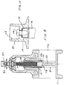
- valve housing 10 which supports a valve member or plate 12 therein for movement along a normally vertical axis 14 effected by rotation of a valve stem 16 which is rotatably mounted in a cover 18.
- the cover 18 sealingly closes the opening 20 of housing 10.
- the valve member 12 is fully inserted into the flow path 22 of the housing 10 and is located remote from the opening 20 at the upper end of the housing as shown in the drawings.
- the flow path 22 will extend transverse to the longitudinal axis 14 of the housing 10, but it will be understood by those skilled in the art that to accommodate certain installations for customers, other angular orientations are within the scope of this invention.
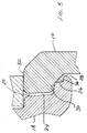
- the housing 10 has a lip 24 surrounding the longitudinal axis 14 and which is smoothly formed such as by casting and with a minimum or no machining. It will also be noted that there is no provision for bolts, screws or the like for fastening the cover 18 to the opening 20 of housing 10.
- the cover 18 is provided with a first L shaped recess 26 about its lower most edge.
- the inner edge of the lip 20 is provided with a peripheral flat surface 28 which extends at an acute angle of approximately 45° relative to the longitudinal axis 14 of the housing 10. From the uppermost edge of the angled surface 28, there extends a flat surface 30 substantially radially with respect to the longitudinal axis 14. Thereafter, the lip extends substantially vertically from surface 30 to the upper rim 32 of the lip 20.
- the vertical edge may have a small slope from the perpendicular from surface 30
- the cover provided for such arrangements would provide identically mating or complementary surfaces to assure a close and tight fit. According to the present invention, however, this is avoided. Instead, the flat surface 30 extends radially with respect to the axis of the housing and therefore of the cover to an extent to provide a gap 34 between the facing surface of the cover 18 and that of the lip 20. With this arrangement, a user will have the option of locating an elastomeric O-ring type sealing member in the L-shaped peripheral recess 26, while the flat surface 30 will engage the underside of the lip 20 as described in more detail hereinafter.
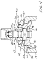
- FIG 4 there is shown the cover 18 in its installed position closing the opening 24 of the housing 10.
- the cover 18 is provided with an upstanding annular shoulder 40 which defines a cavity 42, the upper interior rim of which is smooth and lies adjacent to a threaded portion extending over the remainder of the surface of the interior wall of the cavity 42.
- lugs At approximately the height of the threads on the interior of the shoulder 40, there are provided externally of the shoulder, diametrically opposed radially projecting lugs, one of which is indicated at 44.
- the lugs cooperate with corresponding lugs provided on a locking or retainer ring 46, which will be described below.
- a valve operating stem 16 is inserted through an opening 48, provided in the cover 18. Between the opening 48, which may be a counter bore, there is provided a bore 50 of greater diameter than the counter bore 48. The bore 50 lies immediately beneath the cavity 42.
- the valve operating stem 16 is provided with a collar 52, which fits loosely in the bore 50 and which may be provided with upper and lower friction washers 54.
- a retainer bushing 56 is inserted over the free end of the stem 16 and threaded into the cavity 42 to the position shown.
- the lower most portion of the bushing 56 is provided with depending fingers as at 58, which engage a shoulder provided at the base of the threads of the shoulder portion.
- the bushing 56 is provided with a groove for receiving an O-ring sealing member 60.
- the bushing 56 is provided with a through bore axially aligned with the bore 50 and counter bore 48 to thereby accurately locate the valve stem relative to the valve member located there below as shown in Figures 1 and 2.
- the periphery of the uppermost portion of the valve stem 16 is provided with the conventional sealing members such as the O-rings 62 fitted into mating grooves, as shown.
- valve plate 12 of the present invention has an upper side 4 from which a pair of retaining arms 68 extend to engage a flange 70 provided on a disc nut 72.
- the entire surface of the integrally cast steel valve plate is covered with a compressible elastomer such as buna-n nitrile or rubber.
- the coating has the effect of greatly extending the life of the valve plate by preventing corrosion and to insure excellent sealing of the flow passage.
- the disc nut 72 is formed on opposite sides with parallel extending grooves 74 which extend from the bottom surface of the disc nut 72 at least up to the height of the arms 68.
- the disc nut is cast in brass.
- the coating layer is formed or molded to provide mating tongues 76 which are coextensive in length with the grooves 74 of the disc nut 72.
- valve plate 12 is shown in a position as it is moved towards a retracted condition relative to the flow path 22 of the housing.
- the valve plate is provided with a hollow tubular channel 78 extending entirely therethrough to permit the channel 78 to receive the operating stem 16 upon rotation of the stem effected by rotation of the operating nut 80 secured to the exposed end 82 of the stem 16.
- the flow path 22 of the housing 10 is provided on opposite sides with wall sections 84 defining guide grooves 86 which are located on opposite sides of the valve plate 12. From the direction of entry of the valve plate 12 into the flow path, the sides of each guide groove diverge outwardly at 88 to avoid frictional wear on the elastomer coating of the valve plate 12 and to allow for some deflection of the valve plate during its movement into the flow path.
- the guide grooves will assure proper positioning of the valve plate 12. Above the fully seated position of the valve plate 12 as shown in Figure 1, the grooves are extended to define oppositely disposed guide tracks 92. It will be seen then that, for all positions of the plate 12, the grooves and tracks will guide the plate 12.
- the arcuate seat rim 130 of the valve seat is set back a selected distance H from the center of the guide groove 88.
- the rim 130 engages the upper bead on the valve plate 12 to seal the upper portion of the flow passage.
- the site where the rim 130 intercepts the groove 88 has caused rapid wear and deterioration of the elastomer on the valve plates in the past where the rim was closely adjacent the groove 88 as shown in the prior art structure of Figure 13b.
- the extreme side edges 90 of the valve plate are preferably formed with a pair of detent grooves 94 ( Figure 6B) which serve to anchor a protective shield member or cap 96 as shown in Figures 6A and 6B.
- the caps 96 serve two functions. In coating the valve plate 12 with the elastomer, locater pins are used during the coating process which leave recesses in the coating. The caps serve to cover these recesses and thus remove a potential site for deterioration of the protective elastomeric coating.
- the shield members 96 on the opposite edges will experience the frictional forces normally encountered in movement of the valve plate 12 between its retracted and operational positions and can be readily replaced when damage or wear is apparent, thereby avoiding or greatly postponing the necessity for repair or replacement of the valve plate 12 itself.
- the shield members 96 may be made of a flexible plastic material such as polytetrafluoroethylene or polyethylene or polypropylene, the characteristics of which compounds are particularly useful in this environment.
- the caps By attaching the enlarged opposite ends of the shield or caps 96 in grooves that extend parallel to the direction of travel of the valve plate 12 in operation and thus transverse to the fluid flow, the forces that would tend to dislodge the shield caps 96 whatever the direction of flow through the passage 22 can be tolerated without risk of dislodging the caps 96.
- the caps completely enclose the projecting ends 90 on each side of the valve plate 12.
- the guide grooves 92 on opposite sides of a portion of the path of travel of the valve plate 12 will also cooperate to retain the shield caps 96 in place during valve opening and closing operations.
- valve plate 12 is symmetrical from one side to the other and is preferably formed with an arched elastomer bead 98 on the upper outer surfaces extending between the ends 90 of the valve plate 12 and similarly shaped lower edge sealing surfaces 100 which are formed utilizing using a conventional casting technique for the elastomeric compound. With these shapes, the valve plate will be provided with additional sealing material along is upper and lower edges for cooperating with the opposing surfaces of the housing 10 in use. Of particular importance is the provision of a relatively wide surface area 102 along the base 91 of the valve plate on opposite sides of the channel 78. In addition, along the lower edge of the cast portion of the valve plate 12, a step 101 is formed.
- a dirt seal 102 between the opposing faces of the lip 20 of the housing 10 and the cover 18.
- an elastomer molded to occupy the gap between the opposing surfaces of the lip 20 and cover 18 is provided. It has been found that by installing such a dirt seal 102, positioning of the cover 18 in the opening defined by the lip 20 is greatly facilitated. Further, by locating the primary bearing point between the cover 18 and lip 20 interiorly of the outer edge of the lip and cover as along the surface portion 30 of the lip 20, the tendency of the seal 102 to be extruded by fluid under pressure is greatly minimized.
- the wrench nut 80 is provided with a cavity 110 shaped to conform closely to the slightly tapered knob 112 formed integrally with the stem 16.
- the wrench nut 80 is also provided with a cavity 114 for receiving a socket wrench.
- the base of the cavity 114 is provided with an aperture for receiving a threaded bolt 116 which is received in a threaded bore cast in the upper face of the knob 112.
- a lifting strap 118 may be secured as shown in Figure 11 by passing the opening 120 provided in the strap 118 over the end of the valve stem 16 followed by attachment of the wrench nut 80 as shown. This will provide a secure, yet economical field as well as manufacturing plant lifting ability which is safe in use and which will prevent damage to the protective coating applied to the valve housing 10.
Landscapes
- Engineering & Computer Science (AREA)
- General Engineering & Computer Science (AREA)
- Mechanical Engineering (AREA)
- Sliding Valves (AREA)
Applications Claiming Priority (2)
| Application Number | Priority Date | Filing Date | Title |
|---|---|---|---|
| US997702 | 1993-01-05 | ||
| US07/997,702 US5470046A (en) | 1993-01-05 | 1993-01-05 | Gate valve structure |
Publications (1)
| Publication Number | Publication Date |
|---|---|
| EP0607708A1 true EP0607708A1 (fr) | 1994-07-27 |
Family
ID=25544293
Family Applications (1)
| Application Number | Title | Priority Date | Filing Date |
|---|---|---|---|
| EP93310650A Withdrawn EP0607708A1 (fr) | 1993-01-05 | 1993-12-31 | Vanne d'arrêt |
Country Status (4)
| Country | Link |
|---|---|
| US (1) | US5470046A (fr) |
| EP (1) | EP0607708A1 (fr) |
| AU (2) | AU674549B2 (fr) |
| CA (1) | CA2112836A1 (fr) |
Cited By (3)
| Publication number | Priority date | Publication date | Assignee | Title |
|---|---|---|---|---|
| CN102494150A (zh) * | 2011-12-07 | 2012-06-13 | 深圳大学 | 新型密封结构的闸阀 |
| CN102563105A (zh) * | 2011-12-23 | 2012-07-11 | 上海诺特飞博燃烧设备有限公司 | 一种下开式平板闸阀 |
| US9140368B2 (en) | 2013-03-15 | 2015-09-22 | Mueller International, Llc | Gate valve with track cleanout |
Families Citing this family (9)
| Publication number | Priority date | Publication date | Assignee | Title |
|---|---|---|---|---|
| US6810903B1 (en) * | 1998-04-22 | 2004-11-02 | Hydra-Stop, Inc. | Conduit flow controller |
| FR2846392B1 (fr) † | 2002-10-23 | 2005-09-02 | Saint Gobain Pont A Mousson | Coin d'arret, et vanne d'arret correspondante |
| NO322877B1 (no) * | 2003-06-06 | 2006-12-18 | Danfoss Esco As | Sluseventil |
| US9377037B2 (en) | 2013-03-15 | 2016-06-28 | Ron R. Daniels | Lock device and method of use |
| CN109404562B (zh) * | 2018-12-06 | 2024-03-08 | 江苏雷利电机股份有限公司 | 坐便器用分水机构以及具有所述分水机构的坐便器 |
| US11009149B2 (en) | 2019-04-19 | 2021-05-18 | Mueller International, Llc | Bonnet and stuffing box assembly |
| CN110822114B (zh) * | 2019-12-10 | 2025-02-11 | 浙江展帆实业有限公司 | 一种闸阀 |
| SE545064C2 (sv) * | 2020-06-18 | 2023-03-21 | Sjoeberg Stefan | Rörledningsinsats innefattande en adapter för ett ledningsåtkomstorgan och förfarande för ledningsarbeten |
| CN115654160A (zh) * | 2022-09-21 | 2023-01-31 | 北京航天石化技术装备工程有限公司 | 一种输送密集颗粒流用滑阀 |
Citations (10)
| Publication number | Priority date | Publication date | Assignee | Title |
|---|---|---|---|---|
| US2610820A (en) * | 1946-11-15 | 1952-09-16 | Edward Valves Inc | Valve bonnet structure |
| US3633873A (en) * | 1969-11-28 | 1972-01-11 | Mueller Co | Gate valve structure |
| US3662778A (en) * | 1971-01-05 | 1972-05-16 | Mueller Co | Gate valve structure |
| US3763880A (en) * | 1969-11-28 | 1973-10-09 | Mueller Co | Gate valve structure |
| US4431163A (en) * | 1980-10-24 | 1984-02-14 | Pont-A-Mousson S.A. | Device for fixing a cover on a body and in particular on a valve body |
| DE3440464A1 (de) * | 1984-11-06 | 1986-06-12 | Bopp & Reuther Gmbh, 6800 Mannheim | Absperrschieber |
| EP0314823A1 (fr) * | 1987-11-02 | 1989-05-10 | Johannes Erhard, H. Waldenmaier Erben Süddeutsche Armaturenfabrik GmbH & Co. | Soupape avec couvercle sans vis |
| DE3737162C2 (fr) | 1987-11-02 | 1990-10-04 | Johannes Erhard, H. Waldenmaier Erben, Sueddeutsche Armaturenfabrik Gmbh & Co, 7920 Heidenheim, De | |
| US4968002A (en) * | 1989-05-03 | 1990-11-06 | American Cast Iron Pipe Company | Boltless bonnet assembly for gate valve |
| EP0445020A1 (fr) * | 1990-02-27 | 1991-09-04 | Societe Nouvelle Generale D'hydraulique Et De Mecanique G.H.M. | Robinet-vanne |
Family Cites Families (12)
| Publication number | Priority date | Publication date | Assignee | Title |
|---|---|---|---|---|
| US3170226A (en) * | 1957-08-07 | 1965-02-23 | Mueller Co | Line stopping and valve inserting apparatus and method |
| US3774647A (en) * | 1971-11-04 | 1973-11-27 | Mueller Co | Line stopping assembly using an inflatable element |
| US3809363A (en) * | 1973-04-03 | 1974-05-07 | Mueller Co | Gate valve stem thrust collar lubrication |
| US3963214A (en) * | 1974-11-26 | 1976-06-15 | Mueller Co. | Resilient seated gate valve with split body |
| US3957245A (en) * | 1974-11-26 | 1976-05-18 | Mueller Co. | Gate valve structure |
| US4303223A (en) * | 1977-02-14 | 1981-12-01 | Mueller Co. | Valve facing for sliding valve elements or the like |
| US4162058A (en) * | 1977-05-19 | 1979-07-24 | Mueller Co. | Resilient seated gate valve with improved seat arrangement |
| US4138091A (en) * | 1977-05-25 | 1979-02-06 | Combustion Engineering, Inc. | Drive nut and torque plate assembly |
| US4223868A (en) * | 1979-04-10 | 1980-09-23 | Mueller Co. | Resilient seated gate valve |
| US4607821A (en) * | 1984-01-27 | 1986-08-26 | Bopp & Reuther Gmbh | Shutoff valve |
| NO155943C (no) * | 1984-08-03 | 1987-06-24 | Bopp & Reuther Gmbh | Sleideventil. |
| US4964613A (en) * | 1989-10-18 | 1990-10-23 | Mueller Co. | Gate valve |
-
1993
- 1993-01-05 US US07/997,702 patent/US5470046A/en not_active Expired - Fee Related
- 1993-12-20 AU AU52536/93A patent/AU674549B2/en not_active Ceased
- 1993-12-31 EP EP93310650A patent/EP0607708A1/fr not_active Withdrawn
-
1994
- 1994-01-05 CA CA002112836A patent/CA2112836A1/fr not_active Abandoned
-
1996
- 1996-10-02 AU AU67982/96A patent/AU6798296A/en not_active Abandoned
Patent Citations (10)
| Publication number | Priority date | Publication date | Assignee | Title |
|---|---|---|---|---|
| US2610820A (en) * | 1946-11-15 | 1952-09-16 | Edward Valves Inc | Valve bonnet structure |
| US3633873A (en) * | 1969-11-28 | 1972-01-11 | Mueller Co | Gate valve structure |
| US3763880A (en) * | 1969-11-28 | 1973-10-09 | Mueller Co | Gate valve structure |
| US3662778A (en) * | 1971-01-05 | 1972-05-16 | Mueller Co | Gate valve structure |
| US4431163A (en) * | 1980-10-24 | 1984-02-14 | Pont-A-Mousson S.A. | Device for fixing a cover on a body and in particular on a valve body |
| DE3440464A1 (de) * | 1984-11-06 | 1986-06-12 | Bopp & Reuther Gmbh, 6800 Mannheim | Absperrschieber |
| EP0314823A1 (fr) * | 1987-11-02 | 1989-05-10 | Johannes Erhard, H. Waldenmaier Erben Süddeutsche Armaturenfabrik GmbH & Co. | Soupape avec couvercle sans vis |
| DE3737162C2 (fr) | 1987-11-02 | 1990-10-04 | Johannes Erhard, H. Waldenmaier Erben, Sueddeutsche Armaturenfabrik Gmbh & Co, 7920 Heidenheim, De | |
| US4968002A (en) * | 1989-05-03 | 1990-11-06 | American Cast Iron Pipe Company | Boltless bonnet assembly for gate valve |
| EP0445020A1 (fr) * | 1990-02-27 | 1991-09-04 | Societe Nouvelle Generale D'hydraulique Et De Mecanique G.H.M. | Robinet-vanne |
Cited By (4)
| Publication number | Priority date | Publication date | Assignee | Title |
|---|---|---|---|---|
| CN102494150A (zh) * | 2011-12-07 | 2012-06-13 | 深圳大学 | 新型密封结构的闸阀 |
| CN102563105A (zh) * | 2011-12-23 | 2012-07-11 | 上海诺特飞博燃烧设备有限公司 | 一种下开式平板闸阀 |
| US9140368B2 (en) | 2013-03-15 | 2015-09-22 | Mueller International, Llc | Gate valve with track cleanout |
| US9604260B2 (en) | 2013-03-15 | 2017-03-28 | Mueller International, Llc | Gate valve with track cleanout |
Also Published As
| Publication number | Publication date |
|---|---|
| US5470046A (en) | 1995-11-28 |
| CA2112836A1 (fr) | 1994-07-06 |
| AU5253693A (en) | 1994-07-14 |
| AU674549B2 (en) | 1997-01-02 |
| AU6798296A (en) | 1996-12-19 |
Similar Documents
| Publication | Publication Date | Title |
|---|---|---|
| US5470046A (en) | Gate valve structure | |
| US4073307A (en) | Valve for fire hydrants | |
| EP0004428B1 (fr) | Boisseau sphérique et vanne avec boisseau et sièges démontables pour température élevée | |
| EP0480899A2 (fr) | Presse-étoupe à autoserrage | |
| US4848729A (en) | Valve seal | |
| US6810903B1 (en) | Conduit flow controller | |
| US4860784A (en) | Non-rising stem valve assembly and method of replacing a permanent seal | |
| CA2112718C (fr) | Robinet a obturateur tournant | |
| US6266928B1 (en) | Fuel tank sump containment apparatus | |
| US3782684A (en) | Seat insert for butterfly-type valves | |
| US4577873A (en) | Dual valve stem packing arrangement | |
| US4098490A (en) | Valve body-bonnet joint | |
| US1759221A (en) | Shut-off cock | |
| CA1301017C (fr) | Siege de clapet ameliore | |
| GB1561282A (en) | Butterfly valve thruport seal | |
| EP0298896B1 (fr) | Fixation pour siège de vanne | |
| US20040182567A1 (en) | Wellhead leak containment and blowout deflection apparatus | |
| US7845619B2 (en) | Two-part back cap for a plug valve and plug valves incorporating same | |
| WO1998035176A1 (fr) | Joint d'etancheite | |
| US3272224A (en) | Hooded gas distribution valve for underground use | |
| US2217835A (en) | Valve | |
| US10640956B2 (en) | Adjustable drain valve for dry barrel fire hydrant | |
| KR20230000646A (ko) | 물탱크용 방수 체결구 어셈블리 | |
| CN222864150U (zh) | 带有防护功能的蝶阀 | |
| CN220168611U (zh) | 一种基于户外用明杆闸阀防尘装置 |
Legal Events
| Date | Code | Title | Description |
|---|---|---|---|
| PUAI | Public reference made under article 153(3) epc to a published international application that has entered the european phase |
Free format text: ORIGINAL CODE: 0009012 |
|
| AK | Designated contracting states |
Kind code of ref document: A1 Designated state(s): AT BE CH DE DK ES FR GB GR IE IT LI LU MC NL PT SE |
|
| 17P | Request for examination filed |
Effective date: 19950124 |
|
| 17Q | First examination report despatched |
Effective date: 19960229 |
|
| STAA | Information on the status of an ep patent application or granted ep patent |
Free format text: STATUS: THE APPLICATION IS DEEMED TO BE WITHDRAWN |
|
| 18D | Application deemed to be withdrawn |
Effective date: 19990526 |