EP0607756A2 - Sonde et méthode pour la détection d'un alcool - Google Patents
Sonde et méthode pour la détection d'un alcool Download PDFInfo
- Publication number
- EP0607756A2 EP0607756A2 EP93810915A EP93810915A EP0607756A2 EP 0607756 A2 EP0607756 A2 EP 0607756A2 EP 93810915 A EP93810915 A EP 93810915A EP 93810915 A EP93810915 A EP 93810915A EP 0607756 A2 EP0607756 A2 EP 0607756A2
- Authority
- EP
- European Patent Office
- Prior art keywords
- alcohol
- probe
- liquid
- measuring chamber
- membrane
- Prior art date
- Legal status (The legal status is an assumption and is not a legal conclusion. Google has not performed a legal analysis and makes no representation as to the accuracy of the status listed.)
- Withdrawn
Links
- LFQSCWFLJHTTHZ-UHFFFAOYSA-N Ethanol Chemical compound CCO LFQSCWFLJHTTHZ-UHFFFAOYSA-N 0.000 title claims abstract description 105
- 239000000523 sample Substances 0.000 title claims abstract description 49
- 238000000034 method Methods 0.000 title claims description 29
- 239000007788 liquid Substances 0.000 claims abstract description 37
- 239000012528 membrane Substances 0.000 claims abstract description 36
- 238000010926 purge Methods 0.000 claims abstract description 33
- 238000001514 detection method Methods 0.000 claims abstract description 15
- 239000007789 gas Substances 0.000 claims description 38
- VZGDMQKNWNREIO-UHFFFAOYSA-N tetrachloromethane Chemical compound ClC(Cl)(Cl)Cl VZGDMQKNWNREIO-UHFFFAOYSA-N 0.000 claims description 12
- 230000008569 process Effects 0.000 claims description 11
- 238000005259 measurement Methods 0.000 claims description 9
- 230000003197 catalytic effect Effects 0.000 claims description 8
- 230000001590 oxidative effect Effects 0.000 claims description 8
- QVGXLLKOCUKJST-UHFFFAOYSA-N atomic oxygen Chemical compound [O] QVGXLLKOCUKJST-UHFFFAOYSA-N 0.000 claims description 5
- 238000006243 chemical reaction Methods 0.000 claims description 5
- 239000001301 oxygen Substances 0.000 claims description 5
- 229910052760 oxygen Inorganic materials 0.000 claims description 5
- 229920006395 saturated elastomer Polymers 0.000 claims description 5
- 238000003380 quartz crystal microbalance Methods 0.000 claims description 3
- XLYOFNOQVPJJNP-UHFFFAOYSA-N water Substances O XLYOFNOQVPJJNP-UHFFFAOYSA-N 0.000 abstract description 5
- -1 ethanol Chemical compound 0.000 abstract 1
- XOLBLPGZBRYERU-UHFFFAOYSA-N tin dioxide Chemical compound O=[Sn]=O XOLBLPGZBRYERU-UHFFFAOYSA-N 0.000 description 19
- 239000003570 air Substances 0.000 description 14
- 239000012530 fluid Substances 0.000 description 9
- 150000001298 alcohols Chemical class 0.000 description 8
- 239000000203 mixture Substances 0.000 description 8
- 239000000126 substance Substances 0.000 description 8
- 239000010453 quartz Substances 0.000 description 7
- VYPSYNLAJGMNEJ-UHFFFAOYSA-N silicon dioxide Inorganic materials O=[Si]=O VYPSYNLAJGMNEJ-UHFFFAOYSA-N 0.000 description 7
- 239000013078 crystal Substances 0.000 description 6
- 230000004044 response Effects 0.000 description 6
- 238000000576 coating method Methods 0.000 description 5
- 230000005284 excitation Effects 0.000 description 5
- 238000010438 heat treatment Methods 0.000 description 4
- 239000000463 material Substances 0.000 description 4
- OKKJLVBELUTLKV-UHFFFAOYSA-N Methanol Chemical compound OC OKKJLVBELUTLKV-UHFFFAOYSA-N 0.000 description 3
- 239000000654 additive Substances 0.000 description 3
- 230000008901 benefit Effects 0.000 description 3
- 230000008859 change Effects 0.000 description 3
- 239000011248 coating agent Substances 0.000 description 3
- 238000000151 deposition Methods 0.000 description 3
- 230000008021 deposition Effects 0.000 description 3
- 229910044991 metal oxide Inorganic materials 0.000 description 3
- 150000004706 metal oxides Chemical class 0.000 description 3
- 230000003647 oxidation Effects 0.000 description 3
- 238000007254 oxidation reaction Methods 0.000 description 3
- 238000012545 processing Methods 0.000 description 3
- CURLTUGMZLYLDI-UHFFFAOYSA-N Carbon dioxide Chemical compound O=C=O CURLTUGMZLYLDI-UHFFFAOYSA-N 0.000 description 2
- 241000005398 Figaro Species 0.000 description 2
- CPLXHLVBOLITMK-UHFFFAOYSA-N Magnesium oxide Chemical compound [Mg]=O CPLXHLVBOLITMK-UHFFFAOYSA-N 0.000 description 2
- KDLHZDBZIXYQEI-UHFFFAOYSA-N Palladium Chemical compound [Pd] KDLHZDBZIXYQEI-UHFFFAOYSA-N 0.000 description 2
- 230000000996 additive effect Effects 0.000 description 2
- XXROGKLTLUQVRX-UHFFFAOYSA-N allyl alcohol Chemical compound OCC=C XXROGKLTLUQVRX-UHFFFAOYSA-N 0.000 description 2
- 239000003795 chemical substances by application Substances 0.000 description 2
- 238000011109 contamination Methods 0.000 description 2
- 230000001351 cycling effect Effects 0.000 description 2
- 229910052739 hydrogen Inorganic materials 0.000 description 2
- 239000001257 hydrogen Substances 0.000 description 2
- 125000004435 hydrogen atom Chemical class [H]* 0.000 description 2
- 229910052751 metal Inorganic materials 0.000 description 2
- 239000002184 metal Substances 0.000 description 2
- 238000012986 modification Methods 0.000 description 2
- 230000004048 modification Effects 0.000 description 2
- 238000012544 monitoring process Methods 0.000 description 2
- 230000035699 permeability Effects 0.000 description 2
- 239000012466 permeate Substances 0.000 description 2
- 239000012071 phase Substances 0.000 description 2
- 238000004867 photoacoustic spectroscopy Methods 0.000 description 2
- BASFCYQUMIYNBI-UHFFFAOYSA-N platinum Chemical compound [Pt] BASFCYQUMIYNBI-UHFFFAOYSA-N 0.000 description 2
- 229920000642 polymer Polymers 0.000 description 2
- 229920001343 polytetrafluoroethylene Polymers 0.000 description 2
- 239000004810 polytetrafluoroethylene Substances 0.000 description 2
- 238000007789 sealing Methods 0.000 description 2
- 239000007787 solid Substances 0.000 description 2
- 241000894006 Bacteria Species 0.000 description 1
- UGFAIRIUMAVXCW-UHFFFAOYSA-N Carbon monoxide Chemical compound [O+]#[C-] UGFAIRIUMAVXCW-UHFFFAOYSA-N 0.000 description 1
- QPLDLSVMHZLSFG-UHFFFAOYSA-N Copper oxide Chemical compound [Cu]=O QPLDLSVMHZLSFG-UHFFFAOYSA-N 0.000 description 1
- 239000005751 Copper oxide Substances 0.000 description 1
- 241000233866 Fungi Species 0.000 description 1
- ZOKXTWBITQBERF-UHFFFAOYSA-N Molybdenum Chemical compound [Mo] ZOKXTWBITQBERF-UHFFFAOYSA-N 0.000 description 1
- KJTLSVCANCCWHF-UHFFFAOYSA-N Ruthenium Chemical compound [Ru] KJTLSVCANCCWHF-UHFFFAOYSA-N 0.000 description 1
- BQCADISMDOOEFD-UHFFFAOYSA-N Silver Chemical compound [Ag] BQCADISMDOOEFD-UHFFFAOYSA-N 0.000 description 1
- GWEVSGVZZGPLCZ-UHFFFAOYSA-N Titan oxide Chemical compound O=[Ti]=O GWEVSGVZZGPLCZ-UHFFFAOYSA-N 0.000 description 1
- XHCLAFWTIXFWPH-UHFFFAOYSA-N [O-2].[O-2].[O-2].[O-2].[O-2].[V+5].[V+5] Chemical compound [O-2].[O-2].[O-2].[O-2].[O-2].[V+5].[V+5] XHCLAFWTIXFWPH-UHFFFAOYSA-N 0.000 description 1
- 230000001133 acceleration Effects 0.000 description 1
- 238000009825 accumulation Methods 0.000 description 1
- 235000013334 alcoholic beverage Nutrition 0.000 description 1
- 239000012080 ambient air Substances 0.000 description 1
- 230000003321 amplification Effects 0.000 description 1
- 238000004458 analytical method Methods 0.000 description 1
- 239000008346 aqueous phase Substances 0.000 description 1
- 235000013361 beverage Nutrition 0.000 description 1
- 238000009835 boiling Methods 0.000 description 1
- 230000005587 bubbling Effects 0.000 description 1
- 150000001720 carbohydrates Chemical class 0.000 description 1
- 239000001569 carbon dioxide Substances 0.000 description 1
- 229910002092 carbon dioxide Inorganic materials 0.000 description 1
- 229910002091 carbon monoxide Inorganic materials 0.000 description 1
- 239000003054 catalyst Substances 0.000 description 1
- 239000000919 ceramic Substances 0.000 description 1
- 238000005229 chemical vapour deposition Methods 0.000 description 1
- 238000002485 combustion reaction Methods 0.000 description 1
- 239000000470 constituent Substances 0.000 description 1
- 229920001577 copolymer Polymers 0.000 description 1
- 229910000431 copper oxide Inorganic materials 0.000 description 1
- 238000012937 correction Methods 0.000 description 1
- 125000004122 cyclic group Chemical group 0.000 description 1
- 230000003247 decreasing effect Effects 0.000 description 1
- 230000000694 effects Effects 0.000 description 1
- 230000007613 environmental effect Effects 0.000 description 1
- 239000011888 foil Substances 0.000 description 1
- 229920000578 graft copolymer Polymers 0.000 description 1
- 150000005826 halohydrocarbons Chemical class 0.000 description 1
- 229920001519 homopolymer Polymers 0.000 description 1
- 150000002440 hydroxy compounds Chemical class 0.000 description 1
- 238000002347 injection Methods 0.000 description 1
- 239000007924 injection Substances 0.000 description 1
- 229910010272 inorganic material Inorganic materials 0.000 description 1
- 239000011147 inorganic material Substances 0.000 description 1
- 230000003993 interaction Effects 0.000 description 1
- 239000007791 liquid phase Substances 0.000 description 1
- 239000000395 magnesium oxide Substances 0.000 description 1
- 244000005700 microbiome Species 0.000 description 1
- 239000002808 molecular sieve Substances 0.000 description 1
- 229910052750 molybdenum Inorganic materials 0.000 description 1
- 239000011733 molybdenum Substances 0.000 description 1
- 238000003199 nucleic acid amplification method Methods 0.000 description 1
- 229920000620 organic polymer Polymers 0.000 description 1
- 229910052763 palladium Inorganic materials 0.000 description 1
- 230000000704 physical effect Effects 0.000 description 1
- 239000004033 plastic Substances 0.000 description 1
- 229910052697 platinum Inorganic materials 0.000 description 1
- 229920001296 polysiloxane Polymers 0.000 description 1
- 229940058401 polytetrafluoroethylene Drugs 0.000 description 1
- DOKHEARVIDLSFF-UHFFFAOYSA-N prop-1-en-1-ol Chemical compound CC=CO DOKHEARVIDLSFF-UHFFFAOYSA-N 0.000 description 1
- BDERNNFJNOPAEC-UHFFFAOYSA-N propan-1-ol Chemical compound CCCO BDERNNFJNOPAEC-UHFFFAOYSA-N 0.000 description 1
- 238000004451 qualitative analysis Methods 0.000 description 1
- 230000005855 radiation Effects 0.000 description 1
- 230000002441 reversible effect Effects 0.000 description 1
- 229910052703 rhodium Inorganic materials 0.000 description 1
- 239000010948 rhodium Substances 0.000 description 1
- MHOVAHRLVXNVSD-UHFFFAOYSA-N rhodium atom Chemical compound [Rh] MHOVAHRLVXNVSD-UHFFFAOYSA-N 0.000 description 1
- 229910052707 ruthenium Inorganic materials 0.000 description 1
- 239000004065 semiconductor Substances 0.000 description 1
- 230000035945 sensitivity Effects 0.000 description 1
- 229920002379 silicone rubber Polymers 0.000 description 1
- 239000004945 silicone rubber Substances 0.000 description 1
- 229910052709 silver Inorganic materials 0.000 description 1
- 239000004332 silver Substances 0.000 description 1
- URGAHOPLAPQHLN-UHFFFAOYSA-N sodium aluminosilicate Chemical compound [Na+].[Al+3].[O-][Si]([O-])=O.[O-][Si]([O-])=O URGAHOPLAPQHLN-UHFFFAOYSA-N 0.000 description 1
- 238000001179 sorption measurement Methods 0.000 description 1
- 241000894007 species Species 0.000 description 1
- 238000004611 spectroscopical analysis Methods 0.000 description 1
- 238000004528 spin coating Methods 0.000 description 1
- 238000004544 sputter deposition Methods 0.000 description 1
- 229920005613 synthetic organic polymer Polymers 0.000 description 1
- 229910001887 tin oxide Inorganic materials 0.000 description 1
- OGIDPMRJRNCKJF-UHFFFAOYSA-N titanium oxide Inorganic materials [Ti]=O OGIDPMRJRNCKJF-UHFFFAOYSA-N 0.000 description 1
- 229910001935 vanadium oxide Inorganic materials 0.000 description 1
- 239000012808 vapor phase Substances 0.000 description 1
- 239000010457 zeolite Substances 0.000 description 1
Images


Classifications
-
- G—PHYSICS
- G01—MEASURING; TESTING
- G01N—INVESTIGATING OR ANALYSING MATERIALS BY DETERMINING THEIR CHEMICAL OR PHYSICAL PROPERTIES
- G01N33/00—Investigating or analysing materials by specific methods not covered by groups G01N1/00 - G01N31/00
- G01N33/02—Food
- G01N33/14—Beverages
- G01N33/146—Beverages containing alcohol
-
- G—PHYSICS
- G01—MEASURING; TESTING
- G01N—INVESTIGATING OR ANALYSING MATERIALS BY DETERMINING THEIR CHEMICAL OR PHYSICAL PROPERTIES
- G01N33/00—Investigating or analysing materials by specific methods not covered by groups G01N1/00 - G01N31/00
- G01N33/0004—Gaseous mixtures, e.g. polluted air
- G01N33/0009—General constructional details of gas analysers, e.g. portable test equipment
- G01N33/0011—Sample conditioning
-
- G—PHYSICS
- G01—MEASURING; TESTING
- G01N—INVESTIGATING OR ANALYSING MATERIALS BY DETERMINING THEIR CHEMICAL OR PHYSICAL PROPERTIES
- G01N33/00—Investigating or analysing materials by specific methods not covered by groups G01N1/00 - G01N31/00
- G01N33/0004—Gaseous mixtures, e.g. polluted air
- G01N33/0009—General constructional details of gas analysers, e.g. portable test equipment
- G01N33/0027—General constructional details of gas analysers, e.g. portable test equipment concerning the detector
- G01N33/0029—Cleaning of the detector
-
- G—PHYSICS
- G01—MEASURING; TESTING
- G01N—INVESTIGATING OR ANALYSING MATERIALS BY DETERMINING THEIR CHEMICAL OR PHYSICAL PROPERTIES
- G01N33/00—Investigating or analysing materials by specific methods not covered by groups G01N1/00 - G01N31/00
- G01N33/0004—Gaseous mixtures, e.g. polluted air
- G01N33/0009—General constructional details of gas analysers, e.g. portable test equipment
- G01N33/0027—General constructional details of gas analysers, e.g. portable test equipment concerning the detector
- G01N33/0036—General constructional details of gas analysers, e.g. portable test equipment concerning the detector specially adapted to detect a particular component
- G01N33/0047—Organic compounds
Definitions
- the present invention concerns an analytical probe device, (hereinafter "probe” for short) for detecting alcohols such as typically ethanol or other alcohols capable of forming a gas or vapor phase.
- the invention further concerns a method for detecting such alcohols. Detection of ethanol is of primary importance herein but other volatile alcohols can also be detected as will be explained in more detail below.
- the term "detecting” as used herein refers to a quantitative rather than a merely qualitative analysis.
- a field of particular interest for the present invention is the in-line determination of a concentration of ethanol in an "inert" liquid, i.e. any liquid that is not capable of forming an oxidizable vapor, such as typically water, e.g. in the form of the aqueous phase of a beverage.
- an "inert" liquid i.e. any liquid that is not capable of forming an oxidizable vapor, such as typically water, e.g. in the form of the aqueous phase of a beverage.
- In-line measurement of the concentration of ethanol in a liquid is a problem hitherto solved typically by direct measurement of a combination of two physical properties, such as density, refractive index or sound velocity.
- two physical properties such as density, refractive index or sound velocity.
- Such prior art methods suffer interference from variations of pressure, dissolved carbon dioxide, and carbohydrate concentrations.
- a probe for in-line measurement of a concentration of a normally volatile alcohol in a flowing liquid, such as a process stream comprising:
- a concentration of a normally volatile alcohol in a flowing liquid e.g. a process stream, comprising:
- said detector includes a reaction means capable of an essentially quantitative exothermal reaction with said alcohol; a first preferred type of such a detector includes a pellistor, i.e. a resistor-based device of the type explained in more detail below. Depending upon the type of detector used the probe contains a catalytic means capable of oxidizing the alcohol in the presence of oxygen.
- a second preferred type of a detector for use in the invention is a gas-sensitive semiconductor also explained in more detail below.
- a third preferred type of a detector for use in the invention is a piezoelectric quartz crystal provided with a coating capable of reversibly absorbing or adsorbing alcohol.
- a forth preferred type of detector for use in the invention is a photoacoustic detector, i.e. a measuring volume equipped with a pulsed or chopped infrared source and a microphone.
- the purge gas contains a component capable of oxidizing alcohol in an exothermic reaction; frequently it is preferred that the purge gas includes carbon tetrachloride, preferably in the form of air saturated therewith.
- response times of less than 10 minutes, e.g. 5 minutes can be obtained for a 90% response with a sensitivity in the order of 1 mbar (millibar; partial pressure of the vapor of the alcohol of interest) as will be explained in more detail below, and such response can be obtained in an essentially continuous manner and in in-line operation of the probe, e.g. while connected with a vessel or conduit containing the medium in which the alcohol or ethanol concentrations is to be measured.
- a probe for continuous in-line operation it is a particular advantage of a probe according to the invention that it can be operated in a perfectly sanitary fashion, i.e. without the risk of bio contamination, such as by microorganisms including bacteria and fungi.
- alcohol as used herein is intended to encompass organic hydroxy compounds which are capable of generating an oxidizable or combustible vapor; preferred alcohols are those having a boiling point of below 120°C, preferably below 100°C. Ethanol is a preferred species but methanol, propanol and propenol (allyl alcohol) can be cited by way of further examples.
- a “membrane” as used herein is a normally flexible film formed essentially of a synthetic homopolymer, copolymer graft polymer or a mixture of such synthetic organic polymers.
- the film must be permeable for vapors of the alcohol concerned but must be substantially impermeable for any liquids in which the alcohol might be contained when being measured.
- Films or “foils” of such polymers as polytetrafluoro ethylene, silicone rubber, and other polymers known to be suitable for use with membrane-enclosed sensors in the electroanalytical art can be used.
- Membrane thickness will depend upon permeability of the membrane material in question for the alcohol of interest as well as upon physical and chemical stability of the membrane material under operating conditions (typically in the temperature range between -20° and +100°C). Typical membrane thicknesses will be in the range of from 5 - 500 ⁇ m (micrometers) with a preferred range between 10 and 200 ⁇ m.
- a "liquid” in the sense used herein is any substance that is liquid under normal conditions and does neither permeate through the membrane nor dissolve or otherwise attack the membrane and produces no vapors that would interfere with the intended measurement of the concentration of the alcohol of interest. Obviously, liquids capable of generating an oxidizable vapor would interfere.
- the term "in the vicinity, at least of said flowing liquid or process stream” is intended to indicate that the membrane can be situated directly in the flowing liquid or process stream, or be arranged in a flow chamber connected with said flowing liquid or process stream by means of conduits.
- the measuring chamber is a discrete element having an open end closed against said liquid by said membrane, as well as an inlet port and an outlet port; preferably, the free volume (i.e. the volume portion of the chamber that is accessible to alcohol vapor) of the measuring chamber is small, e.g not exceeding about 1000 ⁇ l (microliters).
- a typical preferred free volume range is between 50 and 500 ⁇ l.
- the pressure means can be a pump for electric, pneumatic or hydraulic actuation, or a pressurized gas, e.g. air, or another gas mixture that includes, or substantially consists of, an oxidizing gaseous material supplied from a pressurized container, or an equivalent device capable of producing a gas flow of at least about 5 times the volume of the measuring chamber per minute.
- Conduits for connecting the pressure means with the measuring chamber can be formed within the probe housing and suitable connecting lines can be formed of metal or plastic; at least one valve for rapidly and automatically closing and opening the access to the measuring chamber, e.g. a valve actuated by a solenoid, is provided and is preferably arranged in the inlet conduit; suitable pressure means including pumps as well as valves for use in or with a probe according to the invention are available from commercial sources.
- the measuring chamber includes a detector capable of an essentially quantitative detection of the alcohol, and capable of generating an electrical signal in proportion with the detection; obviously, the detector must be small enough to fit into the probe.
- a first preferred example of such a detector is a so-called pellistor, i. e. a solid state sensor of the type known also as catalytic calorimeter or microcalorimeter.
- pellistor i. e. a solid state sensor of the type known also as catalytic calorimeter or microcalorimeter.
- it is a device that is capable of converting heat exchanged in a chemical reaction into an electrical signal.
- Such devices are known per se and are described, for example, by Nuscheler, E., in Proc. 2nd Int. Meeting on Chemical Sensors, Bordeaux 1986, 1 - 33, pages 235 - 238, incorporated herein by way of reference.
- Suitable pellistors are available e.g. from Microsens S.A. of Neucaul, Switzerland, Siemens AG, Germany, and Cerchar Sarl, France.
- the pellistor includes a catalyst capable of oxidizing the alcohol of interest.
- the pellistor is composed of two heated resistors operating typically at a temperature in the order of 300°C.
- the other resistor is coated with a catalytic material with a good efficiency for oxidation of alcohol or ethanol, respectively.
- Typical examples include platinum, palladium, copper oxide, vanadium oxide, rhodium, titanium oxide, ruthenium, molybdenum, magnesia and silver.
- a detector suitable for the invention is a gas-sensitive resistor of the type also known as Tagushi sensor, Figaro sensor, metal oxide sensor and tin oxide (actually tin dioxide, SnO2) sensor.
- gas-sensitive resistor of the type also known as Tagushi sensor, Figaro sensor, metal oxide sensor and tin oxide (actually tin dioxide, SnO2) sensor.
- such devices comprise a metal oxide surface that will change its conductivity in response to the adsorption of a gas on the metal oxide surface.
- Suitable devices are obtainable from commercial sources, e.g. from the Figaro Company, Japan, or the Fraunhofer Institut für physikalische Messtechnik ( Germany) or Microsens SA (Switzerland).
- Another detector or detection principle is based on a piezoelectric quartz crystal.
- This type of detector is known per se and has been decribed in detail in the book by Lu and Czandera with the title “Applications of piezoelectric quartz crystal microblanaces” (Elsevier 1984) incorporated herein by way of reference.
- Various coatings on the quartz crystal will make it selectively sensitive to alcohol. Typical examples of such coatings include organic polymers as well as inorganic materials (e.g.
- Ceramics or "molecular sieves” such as zeolites
- spin coating plasma deposition, sputtering, physical or mechanical deposition, chemical vapor deposition, or another method known to be suitable for deposition of films with a thickness in the typical range of from about 10 nm (nanometers) to 100 ⁇ m (micrometers).
- Quartz microbalances are available commercially from various sources including Leybold-Inficon (USA), Balzers AG (Liechtenstein), Edwards Ltd (United Kingdom).
- An accumulation of alcohol in the measuring volume, space or chamber during the measurement cycle according to the invention will cause an increase of the mass of the surface coating and induce a corresponding shift in the resonance frequency of the quartz crystal.
- the mass of the surface coating will decrease and induce a reverse shift in the resonance frequency of the quartz crystal.
- a further means of detecting trace amounts of alcohol in the measuring volume or chamber during the measurement cycle according to the invention is photoacoustic (or optoacoustic) spectroscopy.
- Devices suitable for such photoacoustic spectroscopy generally comprise three essential components, vz. (i) a measuring space or chamber, (ii) an excitation source, such as typically a laser or lamp, and (iii) a microphone. When absorbed by a specific gas, the excitation energy is converted to heat so as to cause an increase of pressure. By chopping the excitation beam, successive pressure surges or pulses will generate a sound corresponding to the chopping frequency. Such sound will be detected by the microphone and converted into an electrical signal in synchronicity with the excitation pulses.
- Suitable excitations sources can be obtained commercially, e.g. from Zeiss (Germany) or PMS Electrooptics (USA). Suitable alternative sources for infrared radiation are manufactured by Oriel (USA) and Osram (Germany). Suitable microphones can be obtained from various sources, e.g. AKG-Telefunken (Germany), Panasonic (Japan) or Brüel and Kjaer (Denmark).
- the liquid as defined above (also termed “ambient” liquid) is contacted with the membrane such that vapor of the alcohol of interest but not the ambient liquid will permeate the membrane and enter into the measuring chamber; the electrical signal that is generated by the detector is fed into an indicator, preferably after suitable amplification.
- the primary signal can be used for generating the desired final output signal in the manner disclosed in the above-mentioned U.S. patent applications, notably in serial No. 07/840,943.
- the measuring chamber is purged intermittently, e.g. with a cycling period of between 10 and 300 seconds and with a controlled (in terms of flow rate, temperature and pressure) stream of a purge gas fed into the inlet port of the measuring chamber.
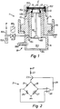
- Probe 1 shown schematically in Fig 1 includes a membrane 10 permeable for alcohols, e.g ethanol, and consisting typically of a thin 10 to 50 ⁇ m, e.g.17 ⁇ m) PTFE film.
- Membrane 10 is held by a support member 13, typically a porous solid layer such as a mesh 101, made for example of metal and held in position within the measuring chamber 11 by a cap 102. Sealing of membrane 10 is effected by means of O-rings 103, 104.
- the interior free volume of chamber 11 is as small as feasible and is formed essentially by the openings within support 13, on the one hand, and any gaps between the detector 12 and both the support 13 as well as the probe housing 14, on the other.
- a sealing means e.g. O-Ring 129, is used to seal detector 12 within chamber 11 such that the open end thereof (defined essentially by the membrane-contacting surface portion of support 13 in Fig. 1) is closed by membrane 10.
- Probe housing 14 is held in place, in a manner known per se, by a mounting collar 16 connected (in a manner not shown) with a measuring site or space containing the external fluid F which, in turn, contains or is suspected to contain the alcohol of interest.
- Detector 12 can be a commercially available device, such as a gas-sensitive reisistor or a pellistors, or a specially designed detector, based either on a modified quartz crystal microbalance or based on an optoacoustic spectrometers as described herein above.
- An inlet conduit 15 opens into that portion of chamber 11 which is essentially defined by voids in support 13.
- Ambient air or another suitable purge gas is introduced via inlet 151 by a pressure means P which might either be a pressure source (e.g. container containing a gas under pressure; not shown) or a pump (not shown) connected with inlet conduit 15 or with outlet conduit 17.
- a valve 153 for closing and opening conduit 151 is operated by an automatic actuator, e.g. a solenoid 159.
- a needle valve 154 serves to maintain a controlled maximum rate of flow of the purge gas through inlet conduit 15 into chamber 12 and through exit conduit 17.
- Valve 154 can be actuated manually or by an electric or equivalent actuator provided within the signal-processing chamber 183 to be explained in more detail below.
- the purge gas (which should contain an oxidizing constituent such as oxygen) or air that enters into conduit portion 151 may be passed through a trap or bubbler 152 filled with a liquid capable of producing a purging additive, such as carbon tetrachloride or another halohydrocarbon. It has been found according to the invention that a significant acceleration of purging or "resetting" can be achieved in this manner.
- a complete reset to "zero-conditions" with air as the purge gas may take 10 to 30 minutes while a reset time of 10 to 30 seconds can be achieved when the purge gas is air saturated with carbon tetrachloride or the like provided as a liquid phase within bubbler 152.
- Outlet conduit 17 can be connected (not shown) with a filter or other device, e.g. a cold trap, to recover the additive from the purge gas and to prevent environmental problems.
- a filter or other device e.g. a cold trap
- Valve 153 with its solenoid drive 159 is used to alternate the probe between "open” and “closed” cycling periods where the free interior volume of measuring chamber 11 is flushed or purged, or is maintained for undisturbed interaction between the detector and the alcohol vapor that has permeated from the external fluid F through membrane 10 into the measuring chamber 11 formed within support 13 and any communicating gaps between detector 12 and immediately adjacent structures.
- An electronic processor 18 is supplied with the primary probe signal produced by detector 12 in response to a given concentration of an alcohol contained in ambient fluid F; the primary signal is passed via an electric connector 181 through a closure plate 182 of the signal processing chamber 183; plate 182 may carry a printed circuit (not shown in Fig. 1) for processing and amplifying (?) the primary signal in a manner known per se and passing the secondary signal via an output connector, e.g. cable 185, to a computing device (not shown) for analysis of the secondary signal and, finally, to an output indicator (not shown) which may be a digital or analogue display, a recorder or other known signal output device.
- Fig.2 illustrates an example of a circuit 2 for maintaining the heating element of a preferred gas-sensitive resistor of the SnO2 type at a constant temperature in the manner of a Wheatstone bridge configuration.
- a DC voltage of for example + 15 Volts is applied at 21.
- the current flowing in each branch of the Wheatstone bridge of Fig. 2 generates a voltage drop at the opposite corners of the bridge.
- heater element 27 gets warmer, its resistance increases and so does the voltage on the inverting input of comparator 29.
- the driving current of transistor 23 will be reduced thus decreasing the total current flowing in the bridge of Fig. 2.
- the heating element 27 cools down, the voltage on the inverting input of comparator 29 becomes smaller than the voltage on the non-inverting input.
- a suitable temperature of heating element 27 (e.g. in the order of 300°C) can be selected by adjusting variable resistor 26.
- Fig. 3 illustrates an example of a circuit 3 including the SnO2 sensitive layer of a probe detector according to the invention. It operates in the manner of a conventional current-to-voltage converter. With a fixed voltage (for example 5 Volts) applied at 31, a variable current will flow in the gas-sensitive resistor 32, depending on its gaseous environment. By means of circuit 3, a voltage will be generated at 36 equal to this current and multiplied by the value of resistor 33. For example, if resistor 33 is, for example, 1 MOhm, a current of 1 ⁇ A flowing through gas-sensitive resistor 32 will generate an output of 1 V on amplifier 34.
- a fixed voltage for example 5 Volts
- Fig. 4 illustrates the electronic circuit 4 for a pellistor suitable as the detector of a probe according to the invention.
- Circuit is supplied at 41 with DC current of + 5 V and fed into a Wheatstone-type circuit including resistor 42 (1 K ⁇ ), a reference heater 43, a device 45 for generating output signal V out , a variable resistor 44 (1 K ⁇ ), resistor 46 (1 K ⁇ ) and a catalytic heater 47.
- resistor 42 (1 K ⁇
- reference heater 43 for generating output signal V out
- a device 45 for generating output signal V out a variable resistor 44 (1 K ⁇ )
- resistor 46 (1 K ⁇ )
- catalytic heater 47 a catalytic heater 47.
- Fig. 5 illustrates a recording of a typical raw output signal of a probe operated according to the invention essentially as indicated above using a gas-sensitive resistor of the SnO2 type as detector 12.
- Current output I in nA (Nanoamperes) is indicated on the ordinate while time t in minutes is indicated on the abscissa.
- Point 51 indicates the moment of ethanol injection; peak 52 indicates the start, trough 53 the end of a purging cycle (valve 153 in open position); conversely, each trough 53 indicates the start of a measuring cycle (valve 153 in closed position) while each peak 52 indicates the end of a measuring cycle.
- An essentially stable value of sucessive peak points 52 is reached after about 10 minutes and four alternating purging and measuring cycles.
- Fig. 6 shows a recording of a typical raw output signal from a probe according to the invention operated with a pellistor as detector 12; the V out signal in mV (millivolts) is indicated on the ordinate, the time t in minutes on the abscissa. Pure ethanol at 25 °C was used as the external fluid; membrane 10 was a silicone membrane of 125 ⁇ m. Double arrow “m” indicates the measuring phase, double arrow "p" the purging phase.
- Fig. 7 is the trace of an analyzer output obtained with a chart recorder.
- Output signal V out in mv (inversely, lower values up) is given on the ordinate, the time in minutes on the abscissa.
- Standard ethanol levels were obtained by bubbling air in ethanol at fixed temperatures; a temperature of -20°C corresponds to a 4 mbar ethanol pressure while a temperature of -10°C corresponds to 8,1 mbar of ethanol (partial pressures).
- a first signal step 71 was recorded when changing from pure air to an ethanol-air mixture saturated at -20°C as the external fluid while a second signal step 72 was recorded when changing to an ethanol-air mixture saturated at -10°C.
- Step 73 was recorded when changing back to passing pure air as the external fluid. Each step change was essentially complete after about 5 minutes.
- a probe essentially as shown in Fig 1. was inserted into the flow chamber through which the ethanol-containing fluid was passed.
- Solenoid valve 153 was opened to let a mixture of air and CCl4 flush the porous support 13, the chamber 11 and the tin dioxide sensor therein. After 1 minute the signal current became essentially stable at typically about 200 nA. Then, valve 153 was closed for 1 minute and the value of the current flowing through the sensitive layer of the detector was recorded. In the absence of ethanol (passage of pure water) the value reached at the end of the purge cycle remained constant during 1 minute.
- a probe according to the invention can be operated in one of two different modes:
- probe structure and probe operation will be apparent to those experienced in the art.
- the structure of the probe may be modified to increase or decrease the free volume of the measuring chamber, to modify the circuitry as well as the operating conditions. Any such modifications are within the scope of the present invention as defined in the subsequent claims.
- Probe and method according to the invention are of use for quantitatively measuring and continuously monitoring other organic substances than alcohols provided that such substance is capable to produce an oxidizable vapor under ambient conditions or at elevated temperatures.
- vapors of suitable substances must be capable of combustion.
- inorganic substances that produce, or exist as, an oxidizable gas or vapor can be measured quantitatively, and monitored continuosly according to the invention include hydrogen, carbon monoxide and the like. While various devices for continuously monitoring such substances are commercially available, it is believed to be an added advantage of the invention that it can be applied to widely varying analytic applications.
Landscapes
- Chemical & Material Sciences (AREA)
- Engineering & Computer Science (AREA)
- Health & Medical Sciences (AREA)
- Life Sciences & Earth Sciences (AREA)
- Food Science & Technology (AREA)
- Biochemistry (AREA)
- Physics & Mathematics (AREA)
- Analytical Chemistry (AREA)
- Medicinal Chemistry (AREA)
- General Health & Medical Sciences (AREA)
- General Physics & Mathematics (AREA)
- Immunology (AREA)
- Pathology (AREA)
- Combustion & Propulsion (AREA)
- Investigating Or Analyzing Materials By The Use Of Fluid Adsorption Or Reactions (AREA)
- Investigating Or Analyzing Materials By The Use Of Electric Means (AREA)
- Sampling And Sample Adjustment (AREA)
Applications Claiming Priority (2)
| Application Number | Priority Date | Filing Date | Title |
|---|---|---|---|
| US5264 | 1993-01-19 | ||
| US08/005,264 US5331845A (en) | 1993-01-19 | 1993-01-19 | Probe and method for detecting alcohol |
Publications (2)
| Publication Number | Publication Date |
|---|---|
| EP0607756A2 true EP0607756A2 (fr) | 1994-07-27 |
| EP0607756A3 EP0607756A3 (fr) | 1996-06-26 |
Family
ID=21715026
Family Applications (1)
| Application Number | Title | Priority Date | Filing Date |
|---|---|---|---|
| EP93810915A Withdrawn EP0607756A3 (fr) | 1993-01-19 | 1993-12-29 | Sonde et méthode pour la détection d'un alcool. |
Country Status (3)
| Country | Link |
|---|---|
| US (1) | US5331845A (fr) |
| EP (1) | EP0607756A3 (fr) |
| JP (1) | JPH06242047A (fr) |
Cited By (6)
| Publication number | Priority date | Publication date | Assignee | Title |
|---|---|---|---|---|
| GB2289944A (en) * | 1994-06-01 | 1995-12-06 | Ranks Hovis Mcdougall Plc | Gas sensing system |
| WO1997021999A1 (fr) * | 1995-12-14 | 1997-06-19 | Lion Laboratories Plc | Procede et appareil pour mesurer la concentration de la vapeur d'ethanol |
| DE19715440C1 (de) * | 1997-04-10 | 1998-08-27 | Inst Bioprozess Analysenmesst | Tauchmeßsonde zur Bestimmung permeabilisierender Analyte |
| AT407091B (de) * | 1997-06-30 | 2000-12-27 | Heimel Helmut | Verfahren zur bestimmung des alkohol- und extraktgehalts einer wässrigen lösung |
| EP1439383A1 (fr) * | 2003-01-20 | 2004-07-21 | Biotechnologie Kempe GmbH | Sonde pour mesurer la concentration en éthanol dans une solution aqueuse |
| WO2012023888A1 (fr) * | 2010-08-19 | 2012-02-23 | Adixen Scandinavia Ab | Boîtier de détecteur de gaz |
Families Citing this family (18)
| Publication number | Priority date | Publication date | Assignee | Title |
|---|---|---|---|---|
| US6124027A (en) * | 1994-05-03 | 2000-09-26 | Ries; Paul D. | Method for making porous zeolitic films |
| JP3126872B2 (ja) * | 1994-05-12 | 2001-01-22 | 三菱電機株式会社 | 燃料の混合比率検知装置 |
| US5451371A (en) * | 1994-06-09 | 1995-09-19 | Ford Motor Company | High-sensitivity, silicon-based, microcalorimetric gas sensor |
| US5481904A (en) * | 1994-09-28 | 1996-01-09 | The United States Of America As Represented By The Secretary Of The Navy | Oil spillage detector |
| FR2728342B1 (fr) * | 1994-12-19 | 1997-01-24 | Inst Francais Du Petrole | Prise de pression selective pour un capteur de pression |
| US5608167A (en) * | 1995-02-21 | 1997-03-04 | Orbisphere Laboratories Neuchatel Sa | Membrane-enclosed sensor, flow control element and analytic method |
| US5979219A (en) * | 1997-02-03 | 1999-11-09 | Sylvia Sellmer Wilsberg | Probe for measuring volatile components in an aqueous solution |
| US5824889A (en) * | 1997-03-06 | 1998-10-20 | Kavlico Corporation | Capacitive oil deterioration and contamination sensor |
| US5929754A (en) * | 1997-12-03 | 1999-07-27 | Kavlico Corporation | High-sensitivity capacitive oil deterioration and level sensor |
| DE19925842C2 (de) * | 1999-06-01 | 2003-12-11 | Ufz Leipzighalle Gmbh | Verfahren zur Messung der Konzentration oder des Partialdruckes von Gasen, insbesondere Sauerstoff, in Fluiden und Gassensor |
| PL354646A1 (en) * | 2000-10-09 | 2004-02-09 | Siemens Building Technologies Ag | Optoacoustic measuring arrangement and use thereof |
| DE10216653A1 (de) * | 2002-04-15 | 2003-11-06 | Biotechnologie Kempe Gmbh | Sonde zur Alkoholmessung in Flüssigkeiten |
| WO2003104767A2 (fr) * | 2002-06-10 | 2003-12-18 | William Marsh Rice University | Spectroscopie photoacoustique renforcee par du quartz |
| DE102004016958B4 (de) * | 2004-04-06 | 2006-08-31 | Testo Ag | Messvorrichtung zum Messen des Zustands von Ölen und Fetten |
| ITRM20090581A1 (it) * | 2009-11-11 | 2011-05-12 | Istituto Naz Per La Ricerca S Ul Cancro | Dispositivo di rilevazione di sostanze volatili, apparato utilizzante tale dispositivo e relativo metodo di funzionamento. |
| JP5888919B2 (ja) | 2010-11-04 | 2016-03-22 | キヤノン株式会社 | 成膜装置及び成膜方法 |
| US10048234B2 (en) | 2012-06-04 | 2018-08-14 | Apix Analytics | Analyzer for fluids containing an inflammable substance and corresponding method |
| JP6569110B2 (ja) * | 2015-09-08 | 2019-09-04 | 京セラ株式会社 | センサモジュール |
Family Cites Families (21)
| Publication number | Priority date | Publication date | Assignee | Title |
|---|---|---|---|---|
| DE258284C (fr) * | ||||
| US3438241A (en) * | 1964-09-23 | 1969-04-15 | Monsanto Co | Gas detection apparatus |
| US3673853A (en) * | 1970-05-11 | 1972-07-04 | Sybron Corp | Gas content of liquid determination |
| US3731523A (en) * | 1971-02-23 | 1973-05-08 | Atomic Energy Commission | Hydrogen activity meter |
| US3871228A (en) * | 1973-05-14 | 1975-03-18 | Us Navy | Permeable membrane gas saturometer |
| US3866460A (en) * | 1973-05-30 | 1975-02-18 | Westinghouse Electric Corp | Gas detector for fluid-filled electrical apparatus |
| HU177965B (en) * | 1976-12-23 | 1982-02-28 | Hiradastechnikai Gepgyar | Method and apparatus for detecting total organic material content lf gases by means of flame ionization detector |
| DE2929013C2 (de) * | 1979-07-18 | 1983-09-08 | Krauss-Maffei AG, 8000 München | Verfahren und Vorrichtung zum Messen der Gasbeladung von Flüssigkeiten |
| CA1167279A (fr) * | 1980-05-20 | 1984-05-15 | Katuo Sugawara | Systeme pour controler les anomalies dans des dispositifs electriques a huile |
| US4461165A (en) * | 1980-06-27 | 1984-07-24 | Scottish & Newcastle Breweries Limited | Method of and apparatus for monitoring concentration of gas in a liquid |
| US4316382A (en) * | 1980-07-21 | 1982-02-23 | Hewlett-Packard Company | Detector with intermittent flow |
| US4463593A (en) * | 1980-11-11 | 1984-08-07 | G. D. Searle & Co. | Apparatus for monitoring the partial pressure of gases |
| US4516580A (en) * | 1981-12-28 | 1985-05-14 | Polanyi Michael L | Continuous blood gas monitoring |
| JPS58158551A (ja) * | 1982-03-16 | 1983-09-20 | Kanegafuchi Chem Ind Co Ltd | 可燃性成分の測定方法 |
| ATE38721T1 (de) * | 1982-08-24 | 1988-12-15 | Scottish & Newcastle Breweries | Verfahren zum ueberwachen einer gaskonzentration in einer fluessigkeit. |
| US4563249A (en) * | 1983-05-10 | 1986-01-07 | Orbisphere Corporation Wilmington, Succursale De Collonge-Bellerive | Electroanalytical method and sensor for hydrogen determination |
| US4517135A (en) * | 1983-06-21 | 1985-05-14 | Pepsico, Inc. | Carbonation measuring system and process |
| JPS61265560A (ja) * | 1985-05-21 | 1986-11-25 | Asahi Breweries Ltd | エタノ−ルセンサ− |
| JPH01140062A (ja) * | 1987-11-26 | 1989-06-01 | Nemoto Tokushu Kagaku Kk | アルコール濃度測定方法及び測定装置 |
| CH679890A5 (fr) * | 1989-11-17 | 1992-04-30 | Orbisphere Lab | |
| US5121627A (en) * | 1990-05-21 | 1992-06-16 | Aoust Brian G D | Integrated miniaturized sensor for measuring total dissolved gas and liquid vapor |
-
1993
- 1993-01-19 US US08/005,264 patent/US5331845A/en not_active Expired - Fee Related
- 1993-12-29 EP EP93810915A patent/EP0607756A3/fr not_active Withdrawn
-
1994
- 1994-01-19 JP JP6004245A patent/JPH06242047A/ja active Pending
Cited By (9)
| Publication number | Priority date | Publication date | Assignee | Title |
|---|---|---|---|---|
| GB2289944A (en) * | 1994-06-01 | 1995-12-06 | Ranks Hovis Mcdougall Plc | Gas sensing system |
| WO1997021999A1 (fr) * | 1995-12-14 | 1997-06-19 | Lion Laboratories Plc | Procede et appareil pour mesurer la concentration de la vapeur d'ethanol |
| US6123828A (en) * | 1995-12-14 | 2000-09-26 | Lion Laboratories Limited | Method and apparatus for measuring ethanol vapor concentration |
| DE19715440C1 (de) * | 1997-04-10 | 1998-08-27 | Inst Bioprozess Analysenmesst | Tauchmeßsonde zur Bestimmung permeabilisierender Analyte |
| AT407091B (de) * | 1997-06-30 | 2000-12-27 | Heimel Helmut | Verfahren zur bestimmung des alkohol- und extraktgehalts einer wässrigen lösung |
| EP1439383A1 (fr) * | 2003-01-20 | 2004-07-21 | Biotechnologie Kempe GmbH | Sonde pour mesurer la concentration en éthanol dans une solution aqueuse |
| US7488449B2 (en) | 2003-01-20 | 2009-02-10 | Biotechnologie Kempe (Gmbh) | Probe device for measuring ethanol concentrations in an aqueous solution |
| WO2012023888A1 (fr) * | 2010-08-19 | 2012-02-23 | Adixen Scandinavia Ab | Boîtier de détecteur de gaz |
| US9285251B2 (en) | 2010-08-19 | 2016-03-15 | Inficon Ab | Gas sensor housing |
Also Published As
| Publication number | Publication date |
|---|---|
| US5331845A (en) | 1994-07-26 |
| EP0607756A3 (fr) | 1996-06-26 |
| JPH06242047A (ja) | 1994-09-02 |
Similar Documents
| Publication | Publication Date | Title |
|---|---|---|
| US5331845A (en) | Probe and method for detecting alcohol | |
| US5361625A (en) | Method and device for the measurement of barrier properties of films against gases | |
| US5731510A (en) | Multi-gas sensor systems for automotive emissions measurement | |
| US4208902A (en) | Gas concentration analysis method and system | |
| Barsan et al. | High-performance gas sensing of CO: comparative tests for semiconducting (SnO2-based) and for amperometric gas sensors | |
| CZ291746B6 (cs) | Způsob stanovení nízkých koncentrací organických sloučenin v znečištěném životním prostředí a zařízení | |
| US6030828A (en) | Microsensor and use of such microsensor | |
| US5683570A (en) | Gas detection method | |
| US5255553A (en) | Method and apparatus for determining specific thermal conductivity parameters of gases | |
| US7398681B2 (en) | Gas sensor based on dynamic thermal conductivity and molecular velocity | |
| US4201634A (en) | Method for the detection of hydrazine | |
| US4169708A (en) | Method and apparatus for gas analysis | |
| US20030121309A1 (en) | Device and method for measuring alcohol vapour concentration | |
| JP3069814B2 (ja) | ガス状物質の特定の熱伝導率パラメータの測定方法及びその装置 | |
| Sujatha et al. | Advances in electronic-nose technologies | |
| Song et al. | A micro hot-wire sensors for gas sensing applications | |
| Becker et al. | Gas mixture analysis using silicon micro-reactor systems | |
| Aroutiounian et al. | P8. 3-Study of MWCNT/SnO2 Nanocomposite Acetone and Toluene Vapor Sensors | |
| Hale et al. | Gas analysis using a thermal conductivity method | |
| Rego et al. | Hydrogen/methane and hydrogen/nitrogen sensor based on the permselectivity of polymeric membranes | |
| RU38945U1 (ru) | Анализатор селективного определения объемной концентрации водорода в газах | |
| EP1439383B1 (fr) | Sonde pour mesurer la concentration en éthanol dans une solution aqueuse | |
| Wiegleb | Physical Gas Sensors | |
| Symanski et al. | Conductometric sensor for atmospheric carbon dioxide determination | |
| Neri et al. | Investigation of permeation tubes for temperature-compensated gas-sensor calibrators |
Legal Events
| Date | Code | Title | Description |
|---|---|---|---|
| PUAI | Public reference made under article 153(3) epc to a published international application that has entered the european phase |
Free format text: ORIGINAL CODE: 0009012 |
|
| AK | Designated contracting states |
Kind code of ref document: A2 Designated state(s): CH DE DK FR GB LI NL |
|
| PUAL | Search report despatched |
Free format text: ORIGINAL CODE: 0009013 |
|
| AK | Designated contracting states |
Kind code of ref document: A3 Designated state(s): CH DE DK FR GB LI NL |
|
| STAA | Information on the status of an ep patent application or granted ep patent |
Free format text: STATUS: THE APPLICATION IS DEEMED TO BE WITHDRAWN |
|
| 18D | Application deemed to be withdrawn |
Effective date: 19961228 |