EP0607763A1 - Anordnung zum dreieckigen Verstellen einer Fräserbefestigungsstange in einer Maschine zum Kantenpolieren von Platten aus Stein, Marmor oder ähnlichen Materialien - Google Patents
Anordnung zum dreieckigen Verstellen einer Fräserbefestigungsstange in einer Maschine zum Kantenpolieren von Platten aus Stein, Marmor oder ähnlichen Materialien Download PDFInfo
- Publication number
- EP0607763A1 EP0607763A1 EP93830462A EP93830462A EP0607763A1 EP 0607763 A1 EP0607763 A1 EP 0607763A1 EP 93830462 A EP93830462 A EP 93830462A EP 93830462 A EP93830462 A EP 93830462A EP 0607763 A1 EP0607763 A1 EP 0607763A1
- Authority
- EP
- European Patent Office
- Prior art keywords
- bar
- mills
- uprights
- shifting
- axes
- Prior art date
- Legal status (The legal status is an assumption and is not a legal conclusion. Google has not performed a legal analysis and makes no representation as to the accuracy of the status listed.)
- Granted
Links
Images


Classifications
-
- B—PERFORMING OPERATIONS; TRANSPORTING
- B24—GRINDING; POLISHING
- B24B—MACHINES, DEVICES, OR PROCESSES FOR GRINDING OR POLISHING; DRESSING OR CONDITIONING OF ABRADING SURFACES; FEEDING OF GRINDING, POLISHING, OR LAPPING AGENTS
- B24B9/00—Machines or devices designed for grinding edges or bevels on work or for removing burrs; Accessories therefor
- B24B9/02—Machines or devices designed for grinding edges or bevels on work or for removing burrs; Accessories therefor characterised by a special design with respect to properties of materials specific to articles to be ground
- B24B9/06—Machines or devices designed for grinding edges or bevels on work or for removing burrs; Accessories therefor characterised by a special design with respect to properties of materials specific to articles to be ground of non-metallic inorganic material, e.g. stone, ceramics, porcelain
Definitions
- the present patent for industrial invention refers to a system which permits a programmable automatic movement on three axes of a mills holder bar such as the bar which is provided on a machine for polishing the edges or profiles of slabs in stone, marble or similar materials.
- Such machines are usually provided with a moving system which moves both the whole tools-spindles assembly and the bar on which such tools are mounted.
- This moving system permits the milling assemblies to be displaced according to both a rectilinear movement and an angular rotation in order that each mill may follow the outline of the edge of the slab to be milled.
- edge polishing machines there are other known edge polishing machines, the capacity of intervention being better.
- these machines have the inconvenience that their working assemblies are excessively complicate as well as the inconvenience that such machine are consequently too difficult and onerous as regards the working.
- the main object of the present invention consists in enhancing the capacity of intervention and the adjusting and moving possibilities of the milling assemblies of the "edge polishing" machines, the necessary simplicity of the operative means being maintained, in order to eliminate the inconveniences which are due on one hand to the limitation in the versatility, and on the other to the complexity of the known machines and all the subsequent consequences.
- the present invention proposes in particular that the adjustment and the displacements of the bar supporting the milling assemblies may be accomplished on three axes, that is along a horizontal and vertical displacement directions and around an axis of angular rotation.
- these three kinds of displacement and adjustment for the tool-holder bar may be all synchronized with one another through a central control device with which it is possible to coordinate and measure the single movements in respect to any shape and dimension of the edge to be milled.
- the present system for displacing the mills holder bar on three axes preferably in a machine for polishing edges of slabs in stone, marble or similar material, characterized mainly in that the ends of the mills holder bar are mounted on pairs of vertical uprights so as to slide and rotate angularly, the vertical uprights being in turn mounted on horizontal guides which are arranged in the upper part of a fixed support; the angular rotation and the vertical sliding of the bar on the respective uprights as well as the sliding of the uprights on the horizontal guides being provoked by corresponding chain gearings, such chains being driven by motors, or by re-circulating ball screws and/or racks, hydraulic cylinders or other similar moving means.
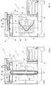
- number 1 indicates a machine for polishing the edges of slabs, preferably in stone, marble or similar material, such machine being provided according to the present invention with a particular moving system for the milling assemblies.
- the machine 1 comprises a base 2 which is provided on the one hand with an assembly which permits the slabs to be supported and to horizontally slide, this assembly comprehending a conveyor belt 3.
- the base 2 is provided with a milling assembly, designated on the whole with the number 4.
- the milling assembly 4 is included in a fixed framework 5 and comprises a horizontal bar 6 which supports a series of spindles 7 with the respective milling tools thereof, the bar 6 being arranged on moving assemblies which permit the bar itself to axially rotate and to be translated according to orthogonal axes.
- the bar 6 is fixed on horizontal shafts 8 which are pivoted upon plates which slide vertically on side uprights 9.
- the bar 6, which supports the milling spindles 7, is moved angularly and may slide vertically on the vertical uprights 9 since the plates that hold the bar 6 itself are moved along vertical guides which are arranged on the vertical uprights 9 and are driven by a trailing system which consists in the present case of chains 16 which are moved on return pulleys 17 through the intervention of a motor 18.
- a shaft 19 connects the movement which is imparted by the motor 18 to the upper return pulleys of both trailing assemblies which are arranged on each upright.
- the chain 16 is hold through brackets 20 on the vertical slide plates of the bar 6. As a consequence of this, the chain 16 itself permits a vertical movement of the bar along the guides of the uprights 9 on which the bar is mounted.
- the vertical uprights 9 are arranged on horizontal guides 21 which are placed in the upper part of the fixed framework 5.
- the displacement of the uprights 9 along the guides 21 is accomplished by a chain system similar to that of the vertical shifting assembly.
- a chain 22 is arranged on return pulleys 23 which are moved by a transmission shaft 24 which is driven by a motor 25, the said chain being connected through brackets 26 with the upper parts of the vertical uprights 9 so that the vertical uprights 9 may be moved horizontally along the guides 21, together with all the supported devices.
- the lower parts of the vertical uprights may be either free or connected with further horizontal slide guides.
- Such a multiple moving system permits the milling assembly 4 to be shifted in a synchronized way according to two translating movements, that is the horizontal movement on the guides 21 and the vertical movement on the uprights 9, and according to a rotary movement on the horizontal axes of the pivoted shafts 8.
- different shifting parameters of the three motorized assemblies are set according to the slab profiles by simply selecting and synchronizing the duration and time of the operation of the single motors through a computerized control device.
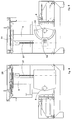
- This variant is represented by a shifting system which comprehends re-circulating ball screws 27 and 28.
- the re-circulating ball screw 27 controls the vertical movement of the tool-holder bar on the uprights 9 while the re-circulating ball screw 28 controls the horizontal movement of the uprights 9 on the guides 21.
- the motorized pulley 29 engages a fixed rim 30 directly and permits an angular shifting of the tool-holder bar 6 on the axis of the horizontal shaft 8 on which the bar itself is mounted.
- FIG. 6 a variant of the movement of the vertical uprights 9 is shown in which the vertical uprights 9 are pivoted in the lower part on fixed shoes 32 through pivots 31 instead of being trailed along the upper guides 21.
- the chain 33 which is similar to the chain 22, is connected through a hinge 34 with a connecting rod 35 which is connected in turn with the fixed framework through a bracket 36. Moreover, the connecting rod 35 engages a pivot 37 which is integral with the uprights 9.
- the connecting rod 35 acts on the pivot 37 and permits the upright 9 to be oscillated onwards or backwards. In this way, it is possible to obtain the same effects of the above-described solution.
Landscapes
- Engineering & Computer Science (AREA)
- Chemical & Material Sciences (AREA)
- Ceramic Engineering (AREA)
- Inorganic Chemistry (AREA)
- Mechanical Engineering (AREA)
- Finish Polishing, Edge Sharpening, And Grinding By Specific Grinding Devices (AREA)
- Grinding Of Cylindrical And Plane Surfaces (AREA)
Applications Claiming Priority (2)
| Application Number | Priority Date | Filing Date | Title |
|---|---|---|---|
| ITVR920100 | 1992-11-20 | ||
| ITVR920100A IT1257688B (it) | 1992-11-20 | 1992-11-20 | Sistema per lo spostamento su tre assi della barra porta frese di macchine per la lucidatura di coste in materiale lapidei o similari |
Publications (2)
| Publication Number | Publication Date |
|---|---|
| EP0607763A1 true EP0607763A1 (de) | 1994-07-27 |
| EP0607763B1 EP0607763B1 (de) | 1997-12-10 |
Family
ID=11427599
Family Applications (1)
| Application Number | Title | Priority Date | Filing Date |
|---|---|---|---|
| EP93830462A Expired - Lifetime EP0607763B1 (de) | 1992-11-20 | 1993-11-18 | Anordnung zum dreieckigen Verstellen einer Fräserbefestigungsstange in einer Maschine zum Kantenpolieren von Platten aus Stein, Marmor oder ähnlichen Materialien |
Country Status (3)
| Country | Link |
|---|---|
| EP (1) | EP0607763B1 (de) |
| DE (2) | DE69315679D1 (de) |
| IT (1) | IT1257688B (de) |
Cited By (1)
| Publication number | Priority date | Publication date | Assignee | Title |
|---|---|---|---|---|
| EP1518641A1 (de) * | 2003-09-29 | 2005-03-30 | MONTRESOR & C. S.r.l. | Vorrichtung zum Polieren von Marmor- oder Stein-Platten mit um einen Drehpunkt rotierenden Kopf |
Citations (2)
| Publication number | Priority date | Publication date | Assignee | Title |
|---|---|---|---|---|
| US1778132A (en) * | 1927-10-10 | 1930-10-14 | Wegner Julius | Stone-working machine |
| EP0296126A2 (de) * | 1987-05-22 | 1988-12-21 | Marmo Meccanica - S.P.A. | Vorrichtung zur Halterung und Bewegung des Werkzeugschlittens auf den automatischen Maschinen zum Polieren der abgerundeten Kanten von Marmor-, Granitplatten und dergleichen |
-
1992
- 1992-11-20 IT ITVR920100A patent/IT1257688B/it active IP Right Grant
-
1993
- 1993-11-18 DE DE69315679T patent/DE69315679D1/de not_active Expired - Lifetime
- 1993-11-18 DE DE0607763T patent/DE607763T1/de active Pending
- 1993-11-18 EP EP93830462A patent/EP0607763B1/de not_active Expired - Lifetime
Patent Citations (2)
| Publication number | Priority date | Publication date | Assignee | Title |
|---|---|---|---|---|
| US1778132A (en) * | 1927-10-10 | 1930-10-14 | Wegner Julius | Stone-working machine |
| EP0296126A2 (de) * | 1987-05-22 | 1988-12-21 | Marmo Meccanica - S.P.A. | Vorrichtung zur Halterung und Bewegung des Werkzeugschlittens auf den automatischen Maschinen zum Polieren der abgerundeten Kanten von Marmor-, Granitplatten und dergleichen |
Cited By (2)
| Publication number | Priority date | Publication date | Assignee | Title |
|---|---|---|---|---|
| EP1518641A1 (de) * | 2003-09-29 | 2005-03-30 | MONTRESOR & C. S.r.l. | Vorrichtung zum Polieren von Marmor- oder Stein-Platten mit um einen Drehpunkt rotierenden Kopf |
| US7070482B2 (en) | 2003-09-29 | 2006-07-04 | Nicola Montresor | Marble or stone slab polishing machine provided with a rotating head mounted on a fulcrum |
Also Published As
| Publication number | Publication date |
|---|---|
| DE607763T1 (de) | 1995-06-08 |
| IT1257688B (it) | 1996-02-01 |
| DE69315679D1 (de) | 1998-01-22 |
| ITVR920100A1 (it) | 1994-05-20 |
| EP0607763B1 (de) | 1997-12-10 |
| ITVR920100A0 (it) | 1992-11-20 |
Similar Documents
| Publication | Publication Date | Title |
|---|---|---|
| US5807044A (en) | Machine tool with pivoting spindle unit | |
| CN211028243U (zh) | 多角度调节的数控铣床结构 | |
| EP1520659B1 (de) | Poliermaschine für Stein- oder Marmorplatten mit einer Schablone | |
| EP0500309A2 (de) | Werkstückhalter | |
| US20050139048A1 (en) | Multiple spindle machine tool | |
| US4493167A (en) | Chamfering machines, particularly for glass sheets | |
| CA2050061C (en) | Machine tool for working flat workpieces | |
| EP0607763B1 (de) | Anordnung zum dreieckigen Verstellen einer Fräserbefestigungsstange in einer Maschine zum Kantenpolieren von Platten aus Stein, Marmor oder ähnlichen Materialien | |
| US3362295A (en) | Work holder | |
| EP0123433B1 (de) | Gelenkige Anordnung von Bauteilen | |
| US5423502A (en) | Apparatus for positioning a sewing work station and method of using same | |
| US3595108A (en) | Apparatus for imparting a non-circular shape to an article | |
| EP0455127B1 (de) | Vorrichtung zum Auswuchten von Rotoren, insbesondere Elektromotorenanker | |
| CN211248844U (zh) | 一种激光切割用便携式滚轮夹具 | |
| GB2146927A (en) | Apparatus for dressing grinding wheels | |
| US3818795A (en) | Gear tooth chamfering | |
| US3917079A (en) | Device for overturning of prismatic bodies | |
| US4496038A (en) | Mechanism for direct transmission of feed movements to the operating units of an automatic machine with revolving table | |
| US3911788A (en) | Milling machine for milling crankwebs and crankpins | |
| US3621618A (en) | Apparatus for producing and machining cyclic non-round profiles | |
| US4265575A (en) | Tooth-edge gear working machine | |
| US4646475A (en) | Abrasive belt surface grinder and method | |
| EP0066318A1 (de) | Maschine zum gleichzeitig Verzapfen der Enden eines Brettes | |
| CN222933082U (zh) | 一种建筑石材加工用支撑设备 | |
| EP0673715A1 (de) | Maschine zum bearbeiten einer glasplatte |
Legal Events
| Date | Code | Title | Description |
|---|---|---|---|
| PUAI | Public reference made under article 153(3) epc to a published international application that has entered the european phase |
Free format text: ORIGINAL CODE: 0009012 |
|
| AK | Designated contracting states |
Kind code of ref document: A1 Designated state(s): DE GB |
|
| 17P | Request for examination filed |
Effective date: 19940919 |
|
| DET | De: translation of patent claims | ||
| 17Q | First examination report despatched |
Effective date: 19960318 |
|
| GRAG | Despatch of communication of intention to grant |
Free format text: ORIGINAL CODE: EPIDOS AGRA |
|
| GRAH | Despatch of communication of intention to grant a patent |
Free format text: ORIGINAL CODE: EPIDOS IGRA |
|
| GRAH | Despatch of communication of intention to grant a patent |
Free format text: ORIGINAL CODE: EPIDOS IGRA |
|
| GRAA | (expected) grant |
Free format text: ORIGINAL CODE: 0009210 |
|
| AK | Designated contracting states |
Kind code of ref document: B1 Designated state(s): DE GB |
|
| REF | Corresponds to: |
Ref document number: 69315679 Country of ref document: DE Date of ref document: 19980122 |
|
| PG25 | Lapsed in a contracting state [announced via postgrant information from national office to epo] |
Ref country code: DE Free format text: LAPSE BECAUSE OF FAILURE TO SUBMIT A TRANSLATION OF THE DESCRIPTION OR TO PAY THE FEE WITHIN THE PRESCRIBED TIME-LIMIT Effective date: 19980311 |
|
| PLBE | No opposition filed within time limit |
Free format text: ORIGINAL CODE: 0009261 |
|
| STAA | Information on the status of an ep patent application or granted ep patent |
Free format text: STATUS: NO OPPOSITION FILED WITHIN TIME LIMIT |
|
| PG25 | Lapsed in a contracting state [announced via postgrant information from national office to epo] |
Ref country code: GB Free format text: LAPSE BECAUSE OF NON-PAYMENT OF DUE FEES Effective date: 19981118 |
|
| 26N | No opposition filed | ||
| GBPC | Gb: european patent ceased through non-payment of renewal fee |
Effective date: 19981118 |