EP0607815A1 - Zweiteilige Absperrvorrichtung für Schläuche für medizinische Zwecke - Google Patents
Zweiteilige Absperrvorrichtung für Schläuche für medizinische Zwecke Download PDFInfo
- Publication number
- EP0607815A1 EP0607815A1 EP94100147A EP94100147A EP0607815A1 EP 0607815 A1 EP0607815 A1 EP 0607815A1 EP 94100147 A EP94100147 A EP 94100147A EP 94100147 A EP94100147 A EP 94100147A EP 0607815 A1 EP0607815 A1 EP 0607815A1
- Authority
- EP
- European Patent Office
- Prior art keywords
- parts
- cap
- sterilization
- beads
- shut
- Prior art date
- Legal status (The legal status is an assumption and is not a legal conclusion. Google has not performed a legal analysis and makes no representation as to the accuracy of the status listed.)
- Granted
Links
- 239000011324 bead Substances 0.000 claims description 10
- 230000001954 sterilising effect Effects 0.000 description 19
- 238000004659 sterilization and disinfection Methods 0.000 description 19
- 239000007789 gas Substances 0.000 description 5
- 239000003814 drug Substances 0.000 description 2
- 230000000694 effects Effects 0.000 description 2
- 238000005516 engineering process Methods 0.000 description 2
- 239000000463 material Substances 0.000 description 2
- 238000000034 method Methods 0.000 description 2
- 238000004806 packaging method and process Methods 0.000 description 2
- -1 polypropylene Polymers 0.000 description 2
- VGGSQFUCUMXWEO-UHFFFAOYSA-N Ethene Chemical compound C=C VGGSQFUCUMXWEO-UHFFFAOYSA-N 0.000 description 1
- 239000005977 Ethylene Substances 0.000 description 1
- 239000004952 Polyamide Substances 0.000 description 1
- 239000004698 Polyethylene Substances 0.000 description 1
- 239000004743 Polypropylene Substances 0.000 description 1
- 230000005540 biological transmission Effects 0.000 description 1
- 239000008280 blood Substances 0.000 description 1
- 210000004369 blood Anatomy 0.000 description 1
- 238000000502 dialysis Methods 0.000 description 1
- 229940079593 drug Drugs 0.000 description 1
- 230000001771 impaired effect Effects 0.000 description 1
- 239000007788 liquid Substances 0.000 description 1
- 239000004033 plastic Substances 0.000 description 1
- 229920003023 plastic Polymers 0.000 description 1
- 229920002647 polyamide Polymers 0.000 description 1
- 229920000515 polycarbonate Polymers 0.000 description 1
- 239000004417 polycarbonate Substances 0.000 description 1
- 229920000573 polyethylene Polymers 0.000 description 1
- 229920001155 polypropylene Polymers 0.000 description 1
- 238000007789 sealing Methods 0.000 description 1
- 238000004073 vulcanization Methods 0.000 description 1
Images
Classifications
-
- A—HUMAN NECESSITIES
- A61—MEDICAL OR VETERINARY SCIENCE; HYGIENE
- A61M—DEVICES FOR INTRODUCING MEDIA INTO, OR ONTO, THE BODY; DEVICES FOR TRANSDUCING BODY MEDIA OR FOR TAKING MEDIA FROM THE BODY; DEVICES FOR PRODUCING OR ENDING SLEEP OR STUPOR
- A61M39/00—Tubes, tube connectors, tube couplings, valves, access sites or the like, specially adapted for medical use
- A61M39/20—Closure caps or plugs for connectors or open ends of tubes
Definitions
- the invention relates to a two-part shut-off device for hoses for medical purposes, comprising a connector which can be connected to the end of the hose and has an internal passage and an external thread, a so-called Luer lock, and a screw cap with an internal thread.
- the invention is concerned with the problem of a shut-off device of the type mentioned To design that on the one hand a perfect sterilization, and preferably a steam sterilization, is possible without the rotary closure cap can unintentionally detach from the nozzle of the shut-off device during the sterilization process or afterwards.
- a two-part shut-off device for hoses for medical purposes which has a connecting piece with an internal passage and an external thread that can be connected to the hose end, a so-called Luer lock, and a screw cap with an internal thread is provided, and that at least one of the two Parts with a self-locking device that allows only slight relative movements, e.g. B. is formed with interacting surfaces with increased frictional resistance, with at least one locking part or with cooperating projections.
- Essential for the invention is the assembly of the nozzle and cap in such a way that on the one hand a slight relative movement of the two parts is possible, so that for example from the inside of the hose the steam passes through the nozzle into the thread and therefore into the outside space can. Since the steam is not used evenly but in a more or less pulsating manner, this ensures that all interior spaces of the shut-off device are properly sterilized.
- the relative movement of the two parts is limited by means which ultimately prevent the twist lock cap from coming off the neck. Relatively small additional forces are required for deliberately loosening the two parts, which are easily applied by an operator, and are even not felt.
- the force exerted by the sterilization medium on the cap is not large enough to move it over the lock.
- the two locking parts are lip-shaped, the radially inwardly protruding lip of the rotary closure cap protruding radially further inwards than the radial lip of the connecting piece protruding outwards.
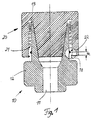
- Fig. 1 shows a nozzle 10 with an inner passage 11 and two diametrically opposed wings 12, which are used for better handling. At its outer end, the nozzle 10 is formed with a thread 13 and an inner cone, while at the opposite end there is a connection to a hose, not shown, in a known manner.
- a rotary cap 20 is formed with a corresponding outer cone and has a thread 21 which fits the thread 13.
- the two parts are shown in the sealing or shut-off position. If the parts are turned further in the direction of the seal, thus, the cones block the interior or the inner passage 11 from the outside.
- the screw cap 20 is slightly twisted off the connector 10, so that the interior or the internal passage 11 is open to the outside via the annular gap between the cone and the spaces in the threads 13 and 21.
- the parts shown in Fig. 1 are plastic parts, for example made of polycarbonate, polypropylene, polyethylene or polyamide.
- the spatial size of these parts is characterized in that for the diameter of the inner passage 11 0.5 to 2 mm 5 to 7 mm or even a few cm are possible, depending on the intended use.
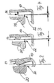
- FIGS. 2 to 4 show further details and show bead-shaped projections 14 (FIGS. 2 and 3) and a lip-shaped projection 14 in FIG. 4.
- These lips or projections 14 each work with corresponding bead-shaped projections of the twist-lock cap 20, specifically with a rounded projection in the embodiment according to FIG. 2 and with lip-shaped projections in the embodiments according to FIGS. 3 to 4.
- the maximum radial extents of the beads 14 and 22 coincide, while in the embodiments according to FIGS. 3 and 4 there are overlaps, so that a certain amount of force is required to unscrew the screw cap 20 from the socket 10.
- the forces required for this are in the range of 10, which is sufficiently large to prevent the twist-on cap 20 from following an internal pressure through the sterilization medium moves over this lock by itself.
- the beads 14 and 22 also prove to be very useful in other contexts, because the two parts are additionally centered relative to one another so that the cap does not wobble excessively on the neck.
- the bead on the cap is preferably displaced in the direction of the thread in order to facilitate screwing the cap onto the socket.
- beads with interruptions but also individual partial projections can be used.
- the maximum radial extent of the beads on the cap is the height of the threads of the thread 21 of the cap. Excessive extension of the beads would impair screwing on or even prevent it.
- the temperature play of the two parts at the vulcanization temperature (approx. 90 ° C) as well as the thermal expansion coefficients of the materials of the cap and nozzle must be taken into account, especially if these are parts made of different materials.
- the beads or lips can also be designed as individual underlap parts.
Landscapes
- Health & Medical Sciences (AREA)
- Heart & Thoracic Surgery (AREA)
- Pulmonology (AREA)
- Engineering & Computer Science (AREA)
- Anesthesiology (AREA)
- Biomedical Technology (AREA)
- Hematology (AREA)
- Life Sciences & Earth Sciences (AREA)
- Animal Behavior & Ethology (AREA)
- General Health & Medical Sciences (AREA)
- Public Health (AREA)
- Veterinary Medicine (AREA)
- Infusion, Injection, And Reservoir Apparatuses (AREA)
- Pipe Accessories (AREA)
- Closures For Containers (AREA)
- Apparatus For Disinfection Or Sterilisation (AREA)
Abstract
Description
- Die Erfindung bezieht sich auf eine zweiteilige Absperrvorrichtung für Schläuche für medizinische Zwecke, aufweisend einen mit dem Schlauchende verbindbaren Stutzen mit Innendurchgang und Außengewinde, einem sog. Luer-Lock negativ, und eine Drehverschlußkappe mit Innengewinde.
- In der Medizintechnik werden Leitungen zur Übertragung von Flüssigkeiten benötigt, an die bzw. an deren Endteile besondere Anforderungen gestellt werden, die in der Technik allgemein sonst nicht üblich sind. Es kommt dabei nicht so sehr auf den speziellen Einsatzzweck in der Medizin an, nämlich ob die Leitung bzw. der Schlauch im Zusammenhang mit Dialysegeräten, bei der Bluttransfusion oder für die Medikamentenversorgung eingesetzt wird. Beim Einsatz derartiger extrakorporaler Schläuche oder Leitungen geht es aber immer darum, daß die Leitung im Innenraum und auch an den Endteilen in perfekt sterilisiertem Zustand vorliegt, da nur so eine einwandfreie Verbindung zwischen dem Patienten und dem zugehörigen Gerät geschaffen werden kann. Es ist daher üblich, die Schläuche zusammen mit ihren Verschlußkappen zu sterilisieren und in einer sterilen Verpackung am Einsatzort zur Verfügung zu stellen. Dort kann dann die entsprechende Verbindung hergestellt werden, wobei sich als Vorschrift durchgesetzt hat, daß nur solche Schläuche eingesetzt werden dürfen, bei denen auch die Verschlußkappe nach der Öffnung der Verpackung sich noch an dem vorgesehenen Ort befindet.
- In der Praxis kommt es nun häufig vor, daß Schlauchgarnituren deshalb verworfen werden, weil die Drehverschlußkappe nicht mehr auf dem Stutzen des Schlauches aufgeschraubt ist, obgleich alle Teile einwandfrei steril sind. Im Laufe der Sterilisation kann sich nämlich durch die Einwirkung des Sterilisationsmediums die Kappe lösen, wodurch die Sterilisationswirkung selbst nicht beeinträchtigt sondern im Gegenteil vielleicht sogar noch verbessert wird, weil das Sterilisationsmedium mit Sicherheit auch alle Teile im Inneren der Absperrvorrichtung erreichen kann.
- In jüngster Zeit setzt sich in zunehmendem Maß die Dampfsterilisation durch, und bei diesem Vorgang wird gerade auf die Drehverschlußkappe einer Absperrvorrichtung derartig eingewirkt, daß diese sich von dem Stutzen lösen will. Die Dampfsterilisation hat jedoch erhebliche Vorteile gegenüber der Gassterilisation, weil bei dieser nie sichergestellt werden kann, daß keine Restgase in der Leitung oder in der Absperrvorrichtung verblieben sind. Im Einsatz können diese Restgase den Patienten erreichen. Bei der Gassterilisation wird vorherrschend Ethylendioxid eingesetzt, ein Gas, das zwar wirksam zum Sterilisieren eingesetzt werden kann, aber äußerst schädlich für den Patienten ist.
- Andererseits ist zu bedenken, daß die Drehverschlußkappe vor der Sterilisation nicht stramm auf den Stutzen aufgeschraubt werden kann, weil in diesem Falle jedwede Sterilisationswirkung im Inneren der Absperrvorrichtung so gut wie ausgeschlossen ist. Es muß also zwischen den beiden Teilen, insbesondere zwischen den Konussen aber auch zwischen den Gewindegängen, genügend Freiraum sein, so daß das Sterilisationsmedium vom Innenraum in den Außenraum und umgekehrt gelangen kann, da nur so eine vollständige Sterilisation möglich ist.
- Die Erfindung befaßt sich mit dem Problem, eine Absperrvorrichtung der eingangs genannten Art so auszugestalten, daß einerseits eine einwandfreie Sterilisation, und zwar vorzugsweise eine Dampfsterilisation, möglich ist, ohne daß andererseits beim Sterilisationsvorgang oder auch nachher die Drehverschlußkappe sich ungewollt vom Stutzen der Absperrvorrichtung lösen kann.
- Erreicht wird dies dadurch, daß eine zweiteilige Absperrvorrichtung für Schläuche für medizinische Zwecke, die einen mit dem Schlauchende verbindbaren Stutzen mit Innendurchgang und Außengewinde aufweist, einem sog. Luer-Lock negativ, und eine Drehverschlußkappe mit Innengewinde vorgesehen ist, und daß mindestens einer der beiden Teile mit einer nur geringe Relativbewegungenzulassenden selbsthemmenden Einrichtung, z. B. mit zusammenwirkenden Flächen mit erhöhtem Reibungswiderstand, mit mindestens einem Sperrteil oder mit zusammenwirkenden Vorsprüngen ausgebildet ist.
- Wesentlich für die Erfindung ist der Zusammenbau von Stutzen und Kappe in der Art, daß einerseits eine geringe Relativbewegung der beiden Teile möglich ist, so daß beispielsweise vom Inneren des Schlauches her der Dampf durch den Stutzen hindurch in das Gewinde und von daher in den Außenraum gelangen kann. Da der Dampf nicht gleichmäßig sondern mehr oder weniger pulsierend eingesetzt wird, kann hierdurch eine einwandfreie Sterilisation aller Innenräume der Absperrvorrichtung sichergestellt werden. Jedoch wird die Relativbewegung der beiden Teile durch Mittel begrenzt, die letzten Endes verhindern, daß die Drehverschlußkappe sich vom Stutzen löst. Zum gewollten Lösen der beiden Teile sind relativ geringe zusätzliche Kräfte erforderlich, die von einer Bedienungsperson ohne weiteres aufgebracht werden, ja sogar nicht einmal gespürt werden. Andererseits ist aber die durch das Sterilisationsmedium ausgeübte Kraft auf die Kappe nicht groß genug, um sie über die Sperre hinweg zu bewegen.
- Bei einer besonders bevorzugten Ausführungsform sind die beiden Sperrteile lippenförmig ausgestaltet, wobei die radial nach innen vorstehende Lippe der Drehverschlußkappe radial weiter nach innen hineinragt als die radiale Lippe des Stutzens nach außen hin vorsteht.
- Die Erfindung wird nachstehend anhand der Zeichnungen beispielsweise erläutert.
- Fig.1
- zeigt eine vergrößerte Querschnittsansicht durch eine Absperrvorrichtung gemäß der Erfindung.
- Figuren 2 bis 4
- zeigen weiter vergrößerte Darstellungen des in Fig. 1 innerhalb eines Kreises gezeigten Bereiches.
- Fig. 1 zeigt einen Stutzen 10 mit einem Innendurchgang 11 und zwei sich diametral gegenüberstehenden Flügeln 12, welche der besseren Handhabung dienen. An seinem äußeren Ende ist der Stutzen 10 mit einem Gewinde 13 und einem Innenkonus ausgebildet, während an dem gegenüberliegenden Ende eine Verbindung zu einem nicht gezeigten Schlauch in bekannter Art und Weise besteht.
- Eine Drehverschlußkappe 20 ist mit einem entsprechenden Außenkonus ausgebildet und weist ein Gewinde 21 auf, welches zu dem Gewinde 13 paßt. In der Fig. 1 sind die beiden Teile in Dicht- bzw. Absperrstellung gezeigt. Werden die Teile weiter in die Dichtrichtung zueinander verdreht, so werden, die Konusse eine Absperrung des Innenraums bzw. des Innendurchgangs 11 nach außen hin bewirken. In der Sterilisationsstellung wird die Drehverschlußkappe 20 etwas von dem Stutzen 10 abgedreht, so daß der Innenraum bzw. der Innendurchgang 11 über den Ringspalt zwischen dem Konus und die Zwischenräume in den Gewinden 13 und 21 nach außen hin offen ist.
- Bei den in Fig. 1 gezeigten Teilen handelt es sich um Kunststoffteile, beispielsweise aus Polycarbonat, Polypropylen, Polyethylen oder Polyamid. Die räumliche Größe dieser Teile sei dadurch gekennzeichnet, daß für den Durchmesser des Innendurchgangs 11 0,5 bis 2 mm 5 bis 7 mm oder sogar einige cm in Frage kommen, was vom Einsatzzweck abhängt.
- Die Fig. 2 bis 4 zeigen weitere Einzelheiten und lassen wulstförmige Vorsprünge 14 (Fig. 2 und 3) sowie einen lippenförmigen Vorsprung 14 in Fig. 4 erkennen. Diese Lippen bzw. Vorsprünge 14 arbeiten jeweils mit entsprechenden wulstförmigen Vorsprüngen der Drehverschlußkappe 20 zusammen, und zwar mit einem abgerundeten Vorsprung in der Ausgestaltung nach Fig. 2 sowie mit lippenförmigen Vorsprüngen bei den Ausführungsformen nach den Fig. 3 bis 4.
- Bei der Ausführungsform nach Fig. 2 fallen die maximalen Radialerstreckungen der Wulste 14 und 22 zusammen, während bei den Ausgestaltungen nach den Fig. 3 und 4 Überlappungen vorliegen, so daß ein gewisser Kraftaufwand erforderlich ist, um die Drehverschlußkappe 20 vom Stutzen 10 abzudrehen. Die hierfür erforderlichen Kräfte liegen jedoch im Bereich von 10 , was ausreichend groß ist, um zu verhindern, daß sich die Drehverschlußkappe 20 zufolge eines Innendruckes durch das Sterilisationsmedium von selbst über diese Sperre hinweg bewegt.
- Die Axialerstreckung A, über die sich die beiden Teile 10 und 20 zueinander verdrehen können, ist in Fig. 1 eingezeichnet, und beläuft sich auf etwa A = 1,5 mm.
- Die Wulste 14 und 22 erweisen sich auch in anderem Zusammenhang als sehr nützlich, weil nämlich eine zusätzliche Zentrierung der beiden Teile zueinander erfolgt, so daß ein übermäßiges Wackeln der Kappe auf dem Stutzen nicht auftritt.
- Bevorzugterweise wird die Wulst an der Kappe in Richtung auf das Gewinde hin versetzt, um das Aufschrauben der Kappe auf den Stutzen zu erleichtern.
- Es ist nicht erforderlich, rundumlaufende Wulste einzusetzen, es können Wulste mit Unterbrechungen aber auch einzelne Teilvorsprünge eingesetzt werden.
- Als maximale Radialerstreckung der Wulste an der Kappe ist die Höhe der Gewindegänge des Gewindes 21 dem Kappe anzusehen. Eine übermäßige Erstreckung der Wulste würde das Aufschrauben beeinträchtigen oder gar verhindern. In diesem Zusammenhang ist auch das Temperaturspiel der beiden Teile bei der Vulkanisationstemperatur ( ca. 90°C) ebenso wie die thermischen Ausdehnungskoeffizienten der Materialien von Kappe und Stutzen zu berücksichtigen, insbesondere wenn es sich hierbei um Teile aus unterschiedlichen Materialien handelt.
- Die Wulste bzw. Lippen können auch als einzelne Hintergreifungsteile ausgestaltet sein.
Claims (3)
- Eine zweiteilige Absperrvorrichtung für Schläuche für medizinische Zwecke, aufweisend einen mit dem Schlauchende verbindbaren Stutzen (10) mit Innendurchgang (11) und Außengewinde (13), einem sog. Luer-Lock negativ, und eine Drehverschlußkappe (20) mit Innengewinde (21), dadurch gekennzeichnet, daß mindestens einer der beiden Teile (10, 20) mit einer nur geringe Relativbewegungen (A) zulassenden selbsthemmenden Einrichtung, z. B. mit zusammenwirkenden Flächen mit erhöhtem Reibungswiderstand, mit mindestens einem Sperrteil oder mit zusammenwirkenden Vorsprüngen (14, 22), ausgebildet ist.
- Vorrichtung nach Anspruch 1, dadurch gekennzeichnet, daß die zusammenwirkenden Vorsprünge als umlaufende Wülste oder Lippen (14, 22) ausgebildet sind, deren Radialerstreckungen (Fig. 3, Fig. 4) sich gegenseitig überlappen.
- Vorrichtung nach Anspruch 2, dadurch gekennzeichnet, daß die Wülste oder Lippen (14) der Drehverschlußkappe (10) in der Nähe ihres freien Randes (Fig. 1) ausgebildet sind.
Applications Claiming Priority (2)
| Application Number | Priority Date | Filing Date | Title |
|---|---|---|---|
| DE9300616U DE9300616U1 (de) | 1993-01-19 | 1993-01-19 | Zweiteilige Absperrvorrichtung für Schläuche für medizinische Zwecke |
| DE9300616U | 1993-01-19 |
Publications (2)
| Publication Number | Publication Date |
|---|---|
| EP0607815A1 true EP0607815A1 (de) | 1994-07-27 |
| EP0607815B1 EP0607815B1 (de) | 2000-07-12 |
Family
ID=6888271
Family Applications (1)
| Application Number | Title | Priority Date | Filing Date |
|---|---|---|---|
| EP94100147A Expired - Lifetime EP0607815B1 (de) | 1993-01-19 | 1994-01-07 | Zweiteilige Absperrvorrichtung für Schläuche für medizinische Zwecke |
Country Status (3)
| Country | Link |
|---|---|
| EP (1) | EP0607815B1 (de) |
| AT (1) | ATE194501T1 (de) |
| DE (2) | DE9300616U1 (de) |
Cited By (3)
| Publication number | Priority date | Publication date | Assignee | Title |
|---|---|---|---|---|
| DE102014002649A1 (de) * | 2014-02-27 | 2015-08-27 | Fresenius Medical Care Deutschland Gmbh | Schraubverbinder für medizinische Schlauchsysteme und medizinische Schlauchsysteme mit Schraubverbinder |
| DE102014002650A1 (de) * | 2014-02-27 | 2015-08-27 | Fresenius Medical Care Deutschland Gmbh | Schraubverbinder für medizinische Schlauchsysteme und medizinisches Schlauchsystem mit Schraubverbinder |
| CN110680443A (zh) * | 2019-11-21 | 2020-01-14 | 陕西省核工业二一五医院 | 一种心脏封堵器 |
Citations (3)
| Publication number | Priority date | Publication date | Assignee | Title |
|---|---|---|---|---|
| NL7301986A (de) * | 1973-02-13 | 1974-08-15 | ||
| DE3515665C1 (de) * | 1985-05-02 | 1986-05-15 | Gerhard 6393 Wehrheim Pfetzing | Verschlußstopfen |
| DE8906628U1 (de) * | 1988-06-01 | 1989-07-27 | Sterimed Gesellschaft für medizinischen Bedarf mbH, 6600 Saarbrücken | Luer-Lock-Überwurfmutter für Katheteransatzstücke |
-
1993
- 1993-01-19 DE DE9300616U patent/DE9300616U1/de not_active Expired - Lifetime
-
1994
- 1994-01-07 AT AT94100147T patent/ATE194501T1/de not_active IP Right Cessation
- 1994-01-07 EP EP94100147A patent/EP0607815B1/de not_active Expired - Lifetime
- 1994-01-07 DE DE59409424T patent/DE59409424D1/de not_active Expired - Lifetime
Patent Citations (3)
| Publication number | Priority date | Publication date | Assignee | Title |
|---|---|---|---|---|
| NL7301986A (de) * | 1973-02-13 | 1974-08-15 | ||
| DE3515665C1 (de) * | 1985-05-02 | 1986-05-15 | Gerhard 6393 Wehrheim Pfetzing | Verschlußstopfen |
| DE8906628U1 (de) * | 1988-06-01 | 1989-07-27 | Sterimed Gesellschaft für medizinischen Bedarf mbH, 6600 Saarbrücken | Luer-Lock-Überwurfmutter für Katheteransatzstücke |
Cited By (3)
| Publication number | Priority date | Publication date | Assignee | Title |
|---|---|---|---|---|
| DE102014002649A1 (de) * | 2014-02-27 | 2015-08-27 | Fresenius Medical Care Deutschland Gmbh | Schraubverbinder für medizinische Schlauchsysteme und medizinische Schlauchsysteme mit Schraubverbinder |
| DE102014002650A1 (de) * | 2014-02-27 | 2015-08-27 | Fresenius Medical Care Deutschland Gmbh | Schraubverbinder für medizinische Schlauchsysteme und medizinisches Schlauchsystem mit Schraubverbinder |
| CN110680443A (zh) * | 2019-11-21 | 2020-01-14 | 陕西省核工业二一五医院 | 一种心脏封堵器 |
Also Published As
| Publication number | Publication date |
|---|---|
| ATE194501T1 (de) | 2000-07-15 |
| EP0607815B1 (de) | 2000-07-12 |
| DE59409424D1 (de) | 2000-08-17 |
| DE9300616U1 (de) | 1993-05-27 |
Similar Documents
| Publication | Publication Date | Title |
|---|---|---|
| DE69630462T2 (de) | Luer-Verbindungssystem | |
| EP0352540B1 (de) | Verschlusskappe für Dialysatoren | |
| DE69820433T2 (de) | Verbindungsanordnung, fluidsysteme und methode zum erstellen einer verbindung | |
| DE60012270T2 (de) | Vebindungsvorrichtungen für Katheter, Perfusionseinrichtungen oder Flüssigkeitsabsaugsysteme | |
| EP0633039B1 (de) | Bajonett-Schlauchverbinder | |
| EP0575916B1 (de) | Blutentnahme-Vorrichtung | |
| DE69523618T2 (de) | Intravenöses verbindungsstück mit ventil für fluidleitung | |
| DE3515665C1 (de) | Verschlußstopfen | |
| DE2828100C2 (de) | Kindersicherer Verschluß | |
| DE3039859C2 (de) | ||
| DE8817024U1 (de) | Gasdichte Verschlußvorrichtung für die Verbindungsenden von Röhren für biomedizinische Flüssigkeitstransporteinrichtungen insbesondere haemodialytische Ketten, welche mittels Sterilisationsgas sterilisiert sind | |
| DE2846677A1 (de) | Aseptisches verbindungsstueck | |
| WO2013149821A1 (de) | Verschlusssystem für einen applikationseinrichtungsansatz an einem behälter für pharmazeutische präparate, und verwendung, behälter mit verschlusssystem, spritze für medizinische zwecke und verfahren zur montage | |
| DE3242238C2 (de) | Katheterkupplung | |
| EP3110496B1 (de) | Schraubverbinder für medizinische schlauchsysteme und medizinische schlauchsysteme mit schraubverbinder | |
| DE19637856C2 (de) | Sterile Konnektoranordnung und Behälter mit einer sterilen Konnektoranordnung | |
| EP2537772A1 (de) | Vorrichtung zur Aufnahme und Abgabe eines Fluids | |
| EP0094101B1 (de) | Steriler Behälter für medizinische Zwecke | |
| DE10160362A1 (de) | Verschlußkappe | |
| DE3737665A1 (de) | Zum verbinden von rohren oder dergleichen vorgesehene vorrichtung | |
| WO2009092430A1 (de) | Spritzensystem und verfahren zu dessen herstellung | |
| EP0607815B1 (de) | Zweiteilige Absperrvorrichtung für Schläuche für medizinische Zwecke | |
| WO2015121296A1 (de) | Vorrichtung zum sterilen verbinden von medizinischen einwegartikeln | |
| DE102019207970A1 (de) | Medizinischer Hohlkörper, medizinischer Hohlkörper mit einer Verschlusskappe, Verfahren zum Herstellen eines medizinischen Hohlkörpers, und Kit | |
| WO2024023082A9 (de) | Verschlusssystem für einen medikamentenbehälter sowie medikamentenbehälter mit einem verschlusssystem |
Legal Events
| Date | Code | Title | Description |
|---|---|---|---|
| PUAI | Public reference made under article 153(3) epc to a published international application that has entered the european phase |
Free format text: ORIGINAL CODE: 0009012 |
|
| AK | Designated contracting states |
Kind code of ref document: A1 Designated state(s): AT BE CH DE DK ES FR GB GR IE IT LI LU MC NL PT SE |
|
| 17P | Request for examination filed |
Effective date: 19941108 |
|
| 17Q | First examination report despatched |
Effective date: 19950313 |
|
| GRAG | Despatch of communication of intention to grant |
Free format text: ORIGINAL CODE: EPIDOS AGRA |
|
| GRAG | Despatch of communication of intention to grant |
Free format text: ORIGINAL CODE: EPIDOS AGRA |
|
| GRAH | Despatch of communication of intention to grant a patent |
Free format text: ORIGINAL CODE: EPIDOS IGRA |
|
| GRAH | Despatch of communication of intention to grant a patent |
Free format text: ORIGINAL CODE: EPIDOS IGRA |
|
| GRAA | (expected) grant |
Free format text: ORIGINAL CODE: 0009210 |
|
| AK | Designated contracting states |
Kind code of ref document: B1 Designated state(s): AT BE CH DE DK ES FR GB GR IE IT LI LU MC NL PT SE |
|
| PG25 | Lapsed in a contracting state [announced via postgrant information from national office to epo] |
Ref country code: GR Free format text: LAPSE BECAUSE OF NON-PAYMENT OF DUE FEES Effective date: 20000712 Ref country code: ES Free format text: THE PATENT HAS BEEN ANNULLED BY A DECISION OF A NATIONAL AUTHORITY Effective date: 20000712 |
|
| REF | Corresponds to: |
Ref document number: 194501 Country of ref document: AT Date of ref document: 20000715 Kind code of ref document: T |
|
| REG | Reference to a national code |
Ref country code: CH Ref legal event code: EP |
|
| REG | Reference to a national code |
Ref country code: IE Ref legal event code: FG4D Free format text: GERMAN |
|
| REF | Corresponds to: |
Ref document number: 59409424 Country of ref document: DE Date of ref document: 20000817 |
|
| ITF | It: translation for a ep patent filed | ||
| GBT | Gb: translation of ep patent filed (gb section 77(6)(a)/1977) |
Effective date: 20000920 |
|
| PG25 | Lapsed in a contracting state [announced via postgrant information from national office to epo] |
Ref country code: SE Free format text: LAPSE BECAUSE OF FAILURE TO SUBMIT A TRANSLATION OF THE DESCRIPTION OR TO PAY THE FEE WITHIN THE PRESCRIBED TIME-LIMIT Effective date: 20001012 Ref country code: PT Free format text: LAPSE BECAUSE OF FAILURE TO SUBMIT A TRANSLATION OF THE DESCRIPTION OR TO PAY THE FEE WITHIN THE PRESCRIBED TIME-LIMIT Effective date: 20001012 Ref country code: DK Free format text: LAPSE BECAUSE OF FAILURE TO SUBMIT A TRANSLATION OF THE DESCRIPTION OR TO PAY THE FEE WITHIN THE PRESCRIBED TIME-LIMIT Effective date: 20001012 |
|
| REG | Reference to a national code |
Ref country code: CH Ref legal event code: NV Representative=s name: KIRKER & CIE SA |
|
| ET | Fr: translation filed | ||
| PG25 | Lapsed in a contracting state [announced via postgrant information from national office to epo] |
Ref country code: LU Free format text: LAPSE BECAUSE OF NON-PAYMENT OF DUE FEES Effective date: 20010107 |
|
| PG25 | Lapsed in a contracting state [announced via postgrant information from national office to epo] |
Ref country code: MC Free format text: LAPSE BECAUSE OF NON-PAYMENT OF DUE FEES Effective date: 20010131 |
|
| PG25 | Lapsed in a contracting state [announced via postgrant information from national office to epo] |
Ref country code: IE Free format text: LAPSE BECAUSE OF NON-PAYMENT OF DUE FEES Effective date: 20010309 |
|
| REG | Reference to a national code |
Ref country code: IE Ref legal event code: FD4D |
|
| PLBE | No opposition filed within time limit |
Free format text: ORIGINAL CODE: 0009261 |
|
| STAA | Information on the status of an ep patent application or granted ep patent |
Free format text: STATUS: NO OPPOSITION FILED WITHIN TIME LIMIT |
|
| 26N | No opposition filed | ||
| REG | Reference to a national code |
Ref country code: GB Ref legal event code: IF02 |
|
| PG25 | Lapsed in a contracting state [announced via postgrant information from national office to epo] |
Ref country code: IT Free format text: LAPSE BECAUSE OF NON-PAYMENT OF DUE FEES Effective date: 20050107 |
|
| PGFP | Annual fee paid to national office [announced via postgrant information from national office to epo] |
Ref country code: CH Payment date: 20100125 Year of fee payment: 17 |
|
| PGRI | Patent reinstated in contracting state [announced from national office to epo] |
Ref country code: IT Effective date: 20091201 |
|
| PGFP | Annual fee paid to national office [announced via postgrant information from national office to epo] |
Ref country code: IT Payment date: 20100126 Year of fee payment: 17 Ref country code: FR Payment date: 20100209 Year of fee payment: 17 |
|
| PGFP | Annual fee paid to national office [announced via postgrant information from national office to epo] |
Ref country code: GB Payment date: 20100121 Year of fee payment: 17 Ref country code: DE Payment date: 20100204 Year of fee payment: 17 Ref country code: BE Payment date: 20100125 Year of fee payment: 17 Ref country code: AT Payment date: 20100120 Year of fee payment: 17 |
|
| PGFP | Annual fee paid to national office [announced via postgrant information from national office to epo] |
Ref country code: NL Payment date: 20100121 Year of fee payment: 17 |
|
| BERE | Be: lapsed |
Owner name: *BUTTNER KLAUS Effective date: 20110131 |
|
| REG | Reference to a national code |
Ref country code: NL Ref legal event code: V1 Effective date: 20110801 |
|
| REG | Reference to a national code |
Ref country code: CH Ref legal event code: PL |
|
| GBPC | Gb: european patent ceased through non-payment of renewal fee |
Effective date: 20110107 |
|
| REG | Reference to a national code |
Ref country code: FR Ref legal event code: ST Effective date: 20110930 |
|
| PG25 | Lapsed in a contracting state [announced via postgrant information from national office to epo] |
Ref country code: CH Free format text: LAPSE BECAUSE OF NON-PAYMENT OF DUE FEES Effective date: 20110131 Ref country code: LI Free format text: LAPSE BECAUSE OF NON-PAYMENT OF DUE FEES Effective date: 20110131 Ref country code: FR Free format text: LAPSE BECAUSE OF NON-PAYMENT OF DUE FEES Effective date: 20110131 |
|
| PG25 | Lapsed in a contracting state [announced via postgrant information from national office to epo] |
Ref country code: AT Free format text: LAPSE BECAUSE OF NON-PAYMENT OF DUE FEES Effective date: 20110107 Ref country code: GB Free format text: LAPSE BECAUSE OF NON-PAYMENT OF DUE FEES Effective date: 20110107 Ref country code: BE Free format text: LAPSE BECAUSE OF NON-PAYMENT OF DUE FEES Effective date: 20110131 |
|
| PG25 | Lapsed in a contracting state [announced via postgrant information from national office to epo] |
Ref country code: IT Free format text: LAPSE BECAUSE OF NON-PAYMENT OF DUE FEES Effective date: 20110107 Ref country code: NL Free format text: LAPSE BECAUSE OF NON-PAYMENT OF DUE FEES Effective date: 20110801 |
|
| REG | Reference to a national code |
Ref country code: DE Ref legal event code: R119 Ref document number: 59409424 Country of ref document: DE Effective date: 20110802 |
|
| PG25 | Lapsed in a contracting state [announced via postgrant information from national office to epo] |
Ref country code: DE Free format text: LAPSE BECAUSE OF NON-PAYMENT OF DUE FEES Effective date: 20110802 |