EP0607878A1 - Dichtungsprofil - Google Patents
Dichtungsprofil Download PDFInfo
- Publication number
- EP0607878A1 EP0607878A1 EP94100475A EP94100475A EP0607878A1 EP 0607878 A1 EP0607878 A1 EP 0607878A1 EP 94100475 A EP94100475 A EP 94100475A EP 94100475 A EP94100475 A EP 94100475A EP 0607878 A1 EP0607878 A1 EP 0607878A1
- Authority
- EP
- European Patent Office
- Prior art keywords
- profile
- sealing profile
- sealing
- facade
- reveal
- Prior art date
- Legal status (The legal status is an assumption and is not a legal conclusion. Google has not performed a legal analysis and makes no representation as to the accuracy of the status listed.)
- Withdrawn
Links
- 238000007789 sealing Methods 0.000 title claims abstract description 41
- 210000002105 tongue Anatomy 0.000 claims description 7
- 230000000694 effects Effects 0.000 abstract description 3
- 208000018672 Dilatation Diseases 0.000 description 2
- 240000003517 Elaeocarpus dentatus Species 0.000 description 1
- 230000037431 insertion Effects 0.000 description 1
- 238000003780 insertion Methods 0.000 description 1
- 210000001503 joint Anatomy 0.000 description 1
- 229920001296 polysiloxane Polymers 0.000 description 1
Images
Classifications
-
- E—FIXED CONSTRUCTIONS
- E06—DOORS, WINDOWS, SHUTTERS, OR ROLLER BLINDS IN GENERAL; LADDERS
- E06B—FIXED OR MOVABLE CLOSURES FOR OPENINGS IN BUILDINGS, VEHICLES, FENCES OR LIKE ENCLOSURES IN GENERAL, e.g. DOORS, WINDOWS, BLINDS, GATES
- E06B3/00—Window sashes, door leaves, or like elements for closing wall or like openings; Layout of fixed or moving closures, e.g. windows in wall or like openings; Features of rigidly-mounted outer frames relating to the mounting of wing frames
- E06B3/54—Fixing of glass panes or like plates
- E06B3/5427—Fixing of glass panes or like plates the panes mounted flush with the surrounding frame or with the surrounding panes
-
- E—FIXED CONSTRUCTIONS
- E04—BUILDING
- E04B—GENERAL BUILDING CONSTRUCTIONS; WALLS, e.g. PARTITIONS; ROOFS; FLOORS; CEILINGS; INSULATION OR OTHER PROTECTION OF BUILDINGS
- E04B2/00—Walls, e.g. partitions, for buildings; Wall construction with regard to insulation; Connections specially adapted to walls
- E04B2/88—Curtain walls
- E04B2/96—Curtain walls comprising panels attached to the structure through mullions or transoms
- E04B2/967—Details of the cross-section of the mullions or transoms
-
- E—FIXED CONSTRUCTIONS
- E04—BUILDING
- E04F—FINISHING WORK ON BUILDINGS, e.g. STAIRS, FLOORS
- E04F13/00—Coverings or linings, e.g. for walls or ceilings
- E04F13/07—Coverings or linings, e.g. for walls or ceilings composed of covering or lining elements; Sub-structures therefor; Fastening means therefor
- E04F13/08—Coverings or linings, e.g. for walls or ceilings composed of covering or lining elements; Sub-structures therefor; Fastening means therefor composed of a plurality of similar covering or lining elements
- E04F13/0889—Coverings or linings, e.g. for walls or ceilings composed of covering or lining elements; Sub-structures therefor; Fastening means therefor composed of a plurality of similar covering or lining elements characterised by the joints between neighbouring elements, e.g. with joint fillings or with tongue and groove connections
Definitions
- the invention relates to a sealing profile for closing the clear space between two facade elements.
- the object of the invention is to develop a sealing profile with improved properties for the stated purpose.
- the seal is designed as a corner vulcanized closed frame, which can already be assembled by the manufacturer of the facade element.
- the central support is approximately U-shaped in cross section. It is advantageous if the U-legs of the middle support are spread apart. This ensures that the U-legs are spread further apart with increasing pressure load, the contact surface of the angled U-leg edges on the reveal increasing. This increasing spreading effect is promoted by the lowest possible coefficient of friction. It is therefore advantageous if the U-legs are supported on a plastic surface of the reveal.
- each longitudinal edge has a tongue, which is supported on the facade element reveal when the sealing profile is mounted, on both sides of the molded-on clamping web.
- the two tongues assigned to a clamping web are directed away from one another in the form of a flat wedge when the sealing profile is not installed.
- the large span of the sealing profile enables even large dilatations of the facade element to be absorbed.
- the sealing profile in conjunction with the rounded outer contour of the sealing profile, it is ensured that when the facade element already equipped with the sealing profile is inserted into the facade substructure, the sealing profile is automatically deformed by acting on the sealing profile of the already installed facade element and is thus prestressed. Because of this deformation, there is, inter alia, a large contact surface between the two sealing profiles of adjacent facade elements which abut one another with the profile body back, and thus a reliable sealing effect.
- the sealing profile according to the invention can be used advantageously where it is a matter of sealing relatively large, but changing gap widths during operation.
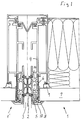
- FIG. 1 shows two facade elements 1, 1 'arranged next to one another with a clear spacing, each of which is equipped with a sealing profile 2 which bears against one another under pressure.
- the two sealing profiles 2 are set back somewhat from the weather-side facade level, close the clear distance between the two facade elements 1, 1 ′ and form a weather-side shadow gap 3 between them.
- Each facade element 1, 1 is composed of a room-side support profile 4 and an outer profile 5, which is firmly connected to the support profile 4 via a plastic profile 6, one leg of the support profile 4 together with the plastic profile 6 and the outer profile 5 having a flat reveal forms. Furthermore, each facade element 1, 1 ′ has a filling element 7, which is pressed against a support seal 9 by inserted pressure springs 8. The outer profile 5 and the leg of the pressure springs 8 which bears against the filling element 7 on the weather side are overlapped by a weather-side seal 10 which is in contact with the sealing profile 2 of the facade element connects and can consist of a corner-connected silicone frame.
- the sealing profile 2 also expediently forms a corner-vulcanized frame with which the facade element can already be fitted by the manufacturer.
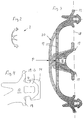
- the profile body 11 of the sealing profile 2 has a slightly curved, approximately C-shaped outer contour according to FIG. 2 in the relaxed state.
- a clamping web 13 is formed on each of the two longitudinal edges 12, with which the sealing profile 2 is pressed into a respective groove 14, 15 in the reveal of the facade element 1, 1 '.
- the profile body 11 also has a central support 16, which is approximately U-shaped in cross-section, the U-legs being spread apart and with their free edge 17 projecting somewhat over the connecting line 18 of the two longitudinal edges 12 mentioned with a relaxed profile .
- Each longitudinal edge 12 of the profile body 11 has a tongue 19 on both sides of the molded-on clamping web 13.
- the two tongues 19 assigned to a clamping web 13 are directed away from one another in the form of a flat wedge (see in particular the dashed illustration in FIG. 3).
- the tongues 19 lie flat against the reveal with the grooves 14, 15 (see FIG. 4 in particular), while the two free edges 17 of the middle support 16 are also supported on the reveal and due to the above called “excess length" are angled slightly outwards.
- the assembled profile body 11 takes the form of a flattened C (see FIGS. 1 and 3) while simultaneously reducing the profile depth.
- the U-legs of the middle support 16 are deformed outwards Increase in the support surface of the free edges 17 on the reveal of the facade element.
- This pushing force P is exerted when a pre-assembled facade element 1 is inserted into the substructure of a facade, specifically from the sealing profile of the adjacent, already suspended facade element 1 '.
- the rounded outer contour of the mutually acting sealing profiles 2 favors the insertion of the facade element 1; there is automatically a deformation of the two sealing profiles 2 coming into contact, as can be seen in FIG. 1.
- the large deformation range of the sealing profile 2 with regard to the profile depth ensures good sealing properties and also enables large dilatations to be taken up from adjacent facade elements.
Landscapes
- Engineering & Computer Science (AREA)
- Architecture (AREA)
- Civil Engineering (AREA)
- Structural Engineering (AREA)
- Physics & Mathematics (AREA)
- Electromagnetism (AREA)
- Glass Compositions (AREA)
- Materials For Medical Uses (AREA)
- Finishing Walls (AREA)
- Building Environments (AREA)
Abstract
Die Erfindung betrifft ein Dichtungsprofil (2) zum Verschließen des lichten Zwischenraumes zwischen zwei Fassadenelementen (1,1'). Zur Verbesserung der Eigenschaften wird eine Profilform mit folgenden Merkmalen vorgeschlagen: a) Der Profilkörper (11) weist in entspanntem Zustand eine leicht gekrümmte, angenähert C-förmige Außenkontur auf; b) an den beiden Längsrändern (12) ist jeweils ein Klemmsteg (13) angeformt zum Eindrücken in jeweils eine in der Laibung des Fassadenelementes (1,1') vorgesehene Nut (14, 15); c) der Profilkörper (11) weist eine mittlere Abstützung (16) auf, deren freier Rand (17) bei entspanntem Profil etwas über die Verbindungslinie (18) der beiden genannten Längsränder (12) hinaus ragt und zur Abstützung des Profils an der Fassadenelement-Laibung dient; d) unter Einwirkung einer senkrecht auf den Profilkörperrücken (20) einwirkenden Druckkraft (P) nimmt der Profilkörper (11) die Form eines abgeflachten C an. <IMAGE>
Description
- Die Erfindung betrifft ein Dichtungsprofil zum Verschließen des lichten Zwischenraumes zwischen zwei Fassadenelementen.
- Eine derartige Ausführungsform läßt sich beispielsweise der EP-A 86115124.9 entnehmen.
- Der Erfindung liegt die Aufgabe zugrunde, für den genannten Zweck ein Dichtungsprofil mit verbesserten Eigenschaften zu entwickeln.
- Diese Aufgabe wird erfindungsgemäß durch folgende Merkmale gelöst:
- a) Der Profilkörper weist in entspanntem Zustand eine leicht gekrümmte, angenähert C-förmige Außenkontur auf;
- b) an den beiden Längsrändern ist jeweils ein Klemmsteg angeformt zum Eindrücken in jeweils eine in der Laibung des Fassadenelementes vorgesehene Nut;
- c) der Profilkörper weist eine mittlere Abstützung auf, deren freier Rand bei entspanntem Profil etwas über die Verbindungslinie der beiden genannten Längsränder hinaus ragt und zur Abstützung des Profils an der Fassadenelement-Laibung dient;
- d) unter Einwirkung einer senkrecht auf den Profilkörperrücken einwirkenden Druckkraft nimmt der Profilkörper die Form eines abgeflachten C an.
- Dabei ist es zweckmäßig, wenn die Dichtung als eckvulkanisierter geschlossener Rahmen ausgebildet ist, der sich bereits beim Hersteller des Fassadenelementes montieren läßt.
- Um eine hochelastische Abstützung des Profilkörpers zu gewährleisten, ist es zweckmäßig, wenn die mittlere Abstützung im Querschnitt angenähert U-förmig ausgebildet ist. Dabei ist es vorteilhaft, wenn die U-Schenkel der mittleren Abstützung voneinander weggespreizt sind. Hierdurch wird erreicht, daß bei zunehmender Druckbelastung die U-Schenkel weiter auseinander gespreizt werden, wobei die Anlagefläche der abgewinkelten U-Schenkelränder an der Laibung zunimmt. Dieser zunehmende Spreizeffekt wird durch einen möglichst niedrigen Reibungskoeffizienten begünstigt. Es ist daher vorteilhaft, wenn sich die U-Schenkel an einer Kunststofffläche der Laibung abstützen.
- Zur Verbesserung der Abdichtung sowie der Stabilität des Dichtungsprofils ist es vorteilhaft, wenn jeder Längsrand beidseitig des angeformten Klemmsteges je eine sich bei montiertem Dichtungsprofil an der Fassadenelement-Laibung abstützende Zunge aufweist. Dabei ist es zur Erzielung einer Vorspannung zweckmäßig, wenn die beiden einem Klemmsteg zugeordneten Zungen bei nicht montiertem Dichtungsprofil flachkeilförmig voneinander weggerichtet sind.
- Die große Überspannung des Dichtungsprofils gibt die Möglichkeit, auch große Dilatationen des Fassadenelementes aufzunehmen. Außerdem ist in Verbindung mit der abgerundeten Außenkontur des Dichtungsprofils gewährleistet, daß beim Einschieben des bereits mit dem Dichtungsprofil bestückten Fassadenelements in die Fassadenunterkonstruktion das Dichtungsprofil durch Beaufschlagung des Dichtungsprofils des bereits montierten Fassadenelementes automatisch verformt und somit vorgespannt wird. Aufgrund dieser Verformung ergibt sich u.a. eine große Anlagefläche zwischen den beiden mit dem Profilkörperrücken aneinander anliegenden Dichtungsprofilen benachbarter Fassadenelemente und damit eine zuverlässige Abdichtwirkung.
- Grundsätzlich läßt sich das erfindungsgemäße Dichtungsprofil dort vorteilhaft einsetzen, wo es um die Abdichtung verhältnismäßig großer, sich im Betrieb jedoch ändernder Spaltbreiten geht.
- In der Zeichnung ist eine als Beispiel dienende Ausführungsform der Erfindung dargestellt. Es zeigen:
- Figur 1
- - etwa im Maßstab 1 : 1 einen Horizontalschnitt durch einen Fassadenelementenstoß mit die Stoßfuge verschließenden Dichtungsprofilen;
- Figur 2
- - im Querschnit ein in Figur 1 dargestelltes Dichtungsprofil in entspanntem Zustand;
- Figur 3
- - in etwa 5facher Vergrößerung die Darstellung gemäß Figur 2 in gestrichelter Wiedergabe und in ausgezogenen Linien die Form des montierten Dichtungsprofils in belastetem Zustand und
- Figur 4
- - in noch einmal vergrößertem Maßstab ein Detail des montierten Dichtungsprofils.
- Figur 1 zeigt zwei mit lichtem Abstand nebeneinander angeordnete Fassadenelemente 1,1', die jeweils mit einem unter Druck aneinander anliegenden Dichtungsprofil 2 bestückt sind. Die beiden Dichtungsprofile 2 sind gegenüber der wetterseitigen Fassadenebene etwas zurückgesetzt, verschließen den lichten Abstand zwischen den beiden Fassadenelementen 1,1' und bilden zwischen diesen eine wetterseitige Schattenfuge 3.
- Jedes Fassadenelement 1,1'setzt sich zusammen aus einem raumseitigen Tragprofil 4 und einem Außenprofil 5, das über ein Kunststoffprofil 6 fest mit dem Tragprofil 4 verbunden ist, wobei ein Schenkel des Tragprofils 4 zusammen mit dem Kunststoffprofil 6 und dem Außenprofil 5 eine flache Laibung bildet. Ferner weist jedes Fassadenelement 1,1' ein Füllelement 7 auf, das von eingeschobenen Andruckfedern 8 gegen eine Auflagedichtung 9 gepreßt wird. Das Außenprofil 5 sowie der wetterseitig am Füllelement 7 anliegende Schenkel der Andruckfedern 8 werden von einer wetterseitigen Dichtung 10 übergriffen, die sich an das Dichtungsprofil 2 des Fassadenelementes anschließt und aus einem eckverbundenen Silikonrahmen bestehen kann.
- Auch das Dichtungsprofil 2 bildet zweckmäßig einen eckvulkanisierten Rahmen, mit dem das Fassadenelement bereits beim Hersteller bestückt werden kann.
- Der Profilkörper 11 des Dichtungsprofils 2 weist gemäß Figur 2 in entspanntem Zustand eine leicht gekrümmte, angenähert C-förmige Außenkontur auf. An den beiden Längsrändern 12 ist jeweils ein Klemmsteg 13 angeformt, mit dem das Dichtungsprofil 2 in jeweils eine Nut 14, 15 in der Laibung des Fassadenelements 1,1' eingedrückt wird. Der Profilkörper 11 weist ferner eine mittlere Abstützung 16 auf, die im Querschnitt angenähert U-förmig ausgebildet ist, wobei die U-Schenkel voneinander weggespreizt sind und mit ihrem freien Rand 17 bei entspanntem Profil etwas über die Verbindungslinie 18 der beiden genannten Längsränder 12 hinaus ragen.
- Jeder Längsrand 12 des Profilkörpers 11 weist beidseitig des angeformten Klemmsteges 13 je eine Zunge 19 auf. Bei nicht montiertem Dichtungsprofil 2 sind die beiden einem Klemmsteg 13 zugeordeten Zungen 19 flachkeilförmig voneinander weggerichtet (siehe insbesondere gestrichelte Darstellung in Figur 3).
- Bei montiertem Dichtungsprofil 2 liegen die Zungen 19 unter leichter Vorspannung flach an der mit den Nuten 14, 15 versehenen Laibung an (siehe isbesondere Figur 4), während die beiden freien Ränder 17 der mittleren Abstützung 16 sich ebenfalls an der Laibung abstützen und aufgrund der vorstehend genannten "Überlänge" etwas nach außen abgewinkelt sind. Unter Einwirkung einer senkrecht auf den Profilkörper 20 einwirkenden Druckkraft P nimmt der montierte Profilkörper 11 die Form eines abgeflachten C an (siehe Figuren 1 und 3) unter gleichzeitiger Reduzierung der Profiltiefe. Zugleich werden die U-Schenkel der mittleren Abstützung 16 nach außen verformt unter Zunahme der Abstützfläche der freien Ränder 17 an der Laibung des Fassadenelementes.
- Diese Druckkraft P wird beim Einschieben eines fertig vormontierten Fassadenelementes 1 in die Unterkonstruktion einer Fassade ausgeübt, und zwar von dem Dichtungsprofil des benachbarten, bereits eingehängten Fassadenelementes 1'. Dabei begünstigt die abgerundete Außenkontur der sich gegenseitig beaufschlagenden Dichtungsprofile 2 das Einschieben des Fassadenelementes 1; es erfolgt automatisch eine Verformung der beiden zur Anlage kommenden Dichtungsprofile 2, wie Figur 1 erkennen läßt.
- Der große Verformungsbereich des Dichtungsprofils 2 hinsichtlich der Profiltiefe gewährleistet gute Abdichtungseigenschaften und ermöglicht außerdem die Aufnahme auch großer Dilatationen benachbarter Fassadenelemente.
Claims (5)
- Dichtungsprofil (2) zum Verschließen des lichten Zwischenraumes zwischen zwei Fassadenelementen (1,1'), gekennzeichnet durch folgende Merkmale:a) Der Profilkörper (11) weist in entspanntem Zustand eine leicht gekrümmte, angenähert C-förmige Außenkontur auf;b) an den beiden Längsrändern (12) ist jeweils ein Klemmsteg (13) angeformt zum Eindrücken in jeweils eine in der Laibung des Fassadenelementes (1,1') vorgesehene Nut (14, 15);c) der Profilkörper (11) weist eine mittlere Abstützung (16) auf, deren freier Rand (17) bei entspanntem Profil etwas über die Verbindungslinie (18) der beiden genannten Längsränder (12) hinaus ragt und zur Abstützung des Profils an der Fassadenelement-Laibung dient;d) unter Einwirkung einer senkrecht auf den Profilkörperrücken (20) einwirkenden Druckkraft (P) nimmt der Profilkörper (11) die Form eines abgeflachten C an.
- Dichtungsprofil nach Anspruch 1, dadurch gekennzeichnet, daß die mittlere Abstützung (16) im Querschnitt angenähert U-förmig ausgebildet ist.
- Dichtungsprofil nach Anspruch 2, dadurch gekennzeichnet, daß die U-Schenkel der mittleren Abstützung (16) voneinander weggespreizt sind;
- Dichtungsprofil nach Anspruch 1, 2 oder 3, dadurch gekennzeichnet, daß jeder Längsrand (12) beidseitig des angeformten Klemmsteges (13) je eine sich bei montiertem Dichtungsprofil (2) an der Fassadenelement-Laibung abstützende Zunge (19) aufweist;
- Dichtungsprofil nach Anspruch 4, dadurch gekennzeichnet, daß die beiden einem Klemmsteg (13) zugeordneten Zungen (19) bei nicht montiertem Dichtungsprofil (2) flachkeilförmig voneinander weggerichtet sind.
Applications Claiming Priority (2)
| Application Number | Priority Date | Filing Date | Title |
|---|---|---|---|
| DE19939300692 DE9300692U1 (de) | 1993-01-20 | 1993-01-20 | Dichtungsprofil |
| DE9300692U | 1993-01-20 |
Publications (1)
| Publication Number | Publication Date |
|---|---|
| EP0607878A1 true EP0607878A1 (de) | 1994-07-27 |
Family
ID=6888328
Family Applications (1)
| Application Number | Title | Priority Date | Filing Date |
|---|---|---|---|
| EP94100475A Withdrawn EP0607878A1 (de) | 1993-01-20 | 1994-01-14 | Dichtungsprofil |
Country Status (2)
| Country | Link |
|---|---|
| EP (1) | EP0607878A1 (de) |
| DE (1) | DE9300692U1 (de) |
Cited By (3)
| Publication number | Priority date | Publication date | Assignee | Title |
|---|---|---|---|---|
| EP0704596A1 (de) * | 1994-09-30 | 1996-04-03 | Reynolds Aluminium Holland B.V. | Feuersicheres Aluminium Gehäuse |
| EP1125815A3 (de) * | 2000-02-14 | 2002-10-02 | Talgo-Transtech OY | Dichtung für eine Schiebehaube eines Eisenbahn-Güterwagens |
| KR100951101B1 (ko) * | 2008-08-27 | 2010-04-07 | 엘아이지건설 주식회사 | 시스템 창호 |
Families Citing this family (3)
| Publication number | Priority date | Publication date | Assignee | Title |
|---|---|---|---|---|
| DE19525955C1 (de) * | 1995-07-17 | 1996-08-14 | Wicona Bausysteme Gmbh | Warmfassade |
| DE19525957C2 (de) * | 1995-07-17 | 2000-02-03 | Wicona Bausysteme Gmbh | Warmfassade |
| DE19617182C2 (de) * | 1996-04-29 | 1999-11-18 | Gerhard Kaese | Drei-Kammer-System mit einer integrierten Mitteldichtung an Pfosten-/Riegelfassaden |
Citations (2)
| Publication number | Priority date | Publication date | Assignee | Title |
|---|---|---|---|---|
| EP0223132A2 (de) * | 1985-11-14 | 1987-05-27 | Eltreva AG | Fassadenkonstruktion aus Metallprofilen |
| EP0430667A2 (de) * | 1989-11-28 | 1991-06-05 | Ebor Holdings Plc | Verkleidungsplattensystem |
-
1993
- 1993-01-20 DE DE19939300692 patent/DE9300692U1/de not_active Expired - Lifetime
-
1994
- 1994-01-14 EP EP94100475A patent/EP0607878A1/de not_active Withdrawn
Patent Citations (2)
| Publication number | Priority date | Publication date | Assignee | Title |
|---|---|---|---|---|
| EP0223132A2 (de) * | 1985-11-14 | 1987-05-27 | Eltreva AG | Fassadenkonstruktion aus Metallprofilen |
| EP0430667A2 (de) * | 1989-11-28 | 1991-06-05 | Ebor Holdings Plc | Verkleidungsplattensystem |
Cited By (4)
| Publication number | Priority date | Publication date | Assignee | Title |
|---|---|---|---|---|
| EP0704596A1 (de) * | 1994-09-30 | 1996-04-03 | Reynolds Aluminium Holland B.V. | Feuersicheres Aluminium Gehäuse |
| NL9401613A (nl) * | 1994-09-30 | 1996-05-01 | Reynolds Aluminium Bv | Brandwerend, aluminium kozijn. |
| EP1125815A3 (de) * | 2000-02-14 | 2002-10-02 | Talgo-Transtech OY | Dichtung für eine Schiebehaube eines Eisenbahn-Güterwagens |
| KR100951101B1 (ko) * | 2008-08-27 | 2010-04-07 | 엘아이지건설 주식회사 | 시스템 창호 |
Also Published As
| Publication number | Publication date |
|---|---|
| DE9300692U1 (de) | 1994-05-26 |
Similar Documents
| Publication | Publication Date | Title |
|---|---|---|
| EP0786576B1 (de) | Elastische Strangdichtung für Fenster, Türen oder dgl. | |
| DE19601505C1 (de) | Glasrandhalterung | |
| DE2844015C2 (de) | Dichtungsprofil für Rolladenkästen | |
| CH647036A5 (de) | Waermedaemmendes verbundprofil, verfahren zu seiner herstellung sowie dessen verwendung. | |
| DE8604761U1 (de) | Streifenprofil | |
| EP0607878A1 (de) | Dichtungsprofil | |
| DE3441444A1 (de) | Glashalteleiste | |
| DE19847955A1 (de) | Dichtungsprofil für Fenster oder Türen | |
| DE2631440A1 (de) | Fassung fuer mehrfachverglasung von fenstern o.dgl. | |
| DE2300359A1 (de) | Druckverglasung fuer metallfenster oder dergl | |
| DE3203253C2 (de) | ||
| EP0066266A1 (de) | Profildichtung | |
| DE9402689U1 (de) | Anschlagdichtung | |
| CH691189A5 (de) | Elastische Strangdichtung zum Abdichten einer Verglasung im Flügel eines Fensters oder einer Türe. | |
| DE3414958A1 (de) | Verklotzungssystem | |
| EP0100558B1 (de) | Kantenschutz für Isolierglas | |
| EP0607866A2 (de) | Füllelement-Halterung für Fassadenelemente, Fenster, Türen oder dergleichen | |
| DE8714246U1 (de) | Elastische Strangdichtung für Türen, Fenster od. dgl. | |
| DE3528388A1 (de) | Elastische profildichtung fuer isolierverglasungen | |
| DE8612008U1 (de) | Verglasungsabdichtung für Flügel von Fenstern, Türen od. dgl. aus Holz | |
| DE19634611C1 (de) | Blendrahmen eines Kunststoff-Fensters oder einer Kunststoff-Türe | |
| DE29603979U1 (de) | Dichtung, insbesondere für Fenster oder Türen | |
| DE4339744A1 (de) | Feuerschutzabschluß im Gebäudebereich, insbesondere Feuerschutz-Tür oder -Fenster | |
| DE2349091C2 (de) | Dachfensterflügel aus Metall für kittlose Verglasung | |
| DE2146853C3 (de) | Verbindungsprofil aus zwei Profilleisten zum Verbinden zweier Ränder bei Fensterverglasungen o.dgl |
Legal Events
| Date | Code | Title | Description |
|---|---|---|---|
| PUAI | Public reference made under article 153(3) epc to a published international application that has entered the european phase |
Free format text: ORIGINAL CODE: 0009012 |
|
| 17P | Request for examination filed |
Effective date: 19940422 |
|
| AK | Designated contracting states |
Kind code of ref document: A1 Designated state(s): CH DE FR GB GR LI NL |
|
| EL | Fr: translation of claims filed | ||
| GBC | Gb: translation of claims filed (gb section 78(7)/1977) | ||
| 17Q | First examination report despatched |
Effective date: 19951201 |
|
| GRAG | Despatch of communication of intention to grant |
Free format text: ORIGINAL CODE: EPIDOS AGRA |
|
| GRAH | Despatch of communication of intention to grant a patent |
Free format text: ORIGINAL CODE: EPIDOS IGRA |
|
| STAA | Information on the status of an ep patent application or granted ep patent |
Free format text: STATUS: THE APPLICATION IS DEEMED TO BE WITHDRAWN |
|
| 18D | Application deemed to be withdrawn |
Effective date: 19960712 |