EP0607913B1 - Dispositif d'alimentation des pièces à usiner dans une machine automatique pour le travail du bois - Google Patents
Dispositif d'alimentation des pièces à usiner dans une machine automatique pour le travail du bois Download PDFInfo
- Publication number
- EP0607913B1 EP0607913B1 EP94100618A EP94100618A EP0607913B1 EP 0607913 B1 EP0607913 B1 EP 0607913B1 EP 94100618 A EP94100618 A EP 94100618A EP 94100618 A EP94100618 A EP 94100618A EP 0607913 B1 EP0607913 B1 EP 0607913B1
- Authority
- EP
- European Patent Office
- Prior art keywords
- clamping
- carriages
- guide track
- haulage way
- strand
- Prior art date
- Legal status (The legal status is an assumption and is not a legal conclusion. Google has not performed a legal analysis and makes no representation as to the accuracy of the status listed.)
- Expired - Lifetime
Links
- 230000008878 coupling Effects 0.000 claims description 7
- 238000010168 coupling process Methods 0.000 claims description 7
- 238000005859 coupling reaction Methods 0.000 claims description 7
- 239000002023 wood Substances 0.000 claims 1
- 238000003754 machining Methods 0.000 description 7
- 238000010276 construction Methods 0.000 description 2
- 238000005299 abrasion Methods 0.000 description 1
- 230000000284 resting effect Effects 0.000 description 1
Images


Classifications
-
- B—PERFORMING OPERATIONS; TRANSPORTING
- B27—WORKING OR PRESERVING WOOD OR SIMILAR MATERIAL; NAILING OR STAPLING MACHINES IN GENERAL
- B27M—WORKING OF WOOD NOT PROVIDED FOR IN SUBCLASSES B27B - B27L; MANUFACTURE OF SPECIFIC WOODEN ARTICLES
- B27M1/00—Working of wood not provided for in subclasses B27B - B27L, e.g. by stretching
- B27M1/08—Working of wood not provided for in subclasses B27B - B27L, e.g. by stretching by multi-step processes
-
- B—PERFORMING OPERATIONS; TRANSPORTING
- B23—MACHINE TOOLS; METAL-WORKING NOT OTHERWISE PROVIDED FOR
- B23Q—DETAILS, COMPONENTS, OR ACCESSORIES FOR MACHINE TOOLS, e.g. ARRANGEMENTS FOR COPYING OR CONTROLLING; MACHINE TOOLS IN GENERAL CHARACTERISED BY THE CONSTRUCTION OF PARTICULAR DETAILS OR COMPONENTS; COMBINATIONS OR ASSOCIATIONS OF METAL-WORKING MACHINES, NOT DIRECTED TO A PARTICULAR RESULT
- B23Q5/00—Driving or feeding mechanisms; Control arrangements therefor
- B23Q5/22—Feeding members carrying tools or work
- B23Q5/34—Feeding other members supporting tools or work, e.g. saddles, tool-slides, through mechanical transmission
-
- B—PERFORMING OPERATIONS; TRANSPORTING
- B27—WORKING OR PRESERVING WOOD OR SIMILAR MATERIAL; NAILING OR STAPLING MACHINES IN GENERAL
- B27C—PLANING, DRILLING, MILLING, TURNING OR UNIVERSAL MACHINES FOR WOOD OR SIMILAR MATERIAL
- B27C9/00—Multi-purpose machines; Universal machines; Equipment therefor
- B27C9/02—Multi-purpose machines; Universal machines; Equipment therefor with a single working spindle
Definitions
- the invention relates to a device for guiding the workpieces in an automatic woodworking machine, in particular for processing squared timber for construction purposes, according to the preamble of claim 1.
- a guide device of this type is known from European patent application 0 267 156. It forms an essential part of the machine for machining described in this document, which can also be referred to as a carpentry machine or woodworking center. Depending on the type of machining intended, the guide device either holds the workpiece or moves it in a straight line when the tool is stationary or moving. In the known CNC-controlled machining system one speaks of five so-called movement axes and one of them is formed by the guide device.
- tensioning carriages In the known guide device, four tensioning carriages are provided. They run on wall-mounted rails and have their own drive motors, the pinions of which mesh with a common rack that is attached next to the rails.
- the clamping carriages can thus move individually, which makes it possible to group them as desired and to place them at a long bar that is suitable for the machining program.
- the carriages coupled to one another by the clamped workpiece run in synchronism. Suitable servomotors and a complex control device are therefore required.
- the invention has for its object to ensure the common CNC-controlled, high-precision drive of the tensioning carriage with unrestricted individual travelability during the machining operations with less technical effort.
- the pull cord is a chain or, according to the preferred embodiment, a toothed belt
- the coupling device comprises a gearwheel mounted on the tensioning carriage in question and meshing with the chain or toothed belt, which gear can be driven by a motor.
- these motors can be simple pole-changing electric motors, since they only serve for the relative movement of the clamping carriages with the workpiece removed and outside of the machining process. As a result of the drive, the tension wagon moves along the train.
- a sensible constructive solution consists in the fact that the guideway consists of two prismatic running tracks running side by side at a distance from the floor, on which the tensioning carriages are guided with free running rollers.
- the running rails are preferably arranged on a hollow profile rail which acts as a supporting element and the other run of the tensile cord runs in the hollow profile rail.
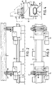
- a machine frame 1 is shown in the middle, on which a tool slide 2 is movably arranged.
- the tool is attached to a bar 3 which is guided under or through the machine frame, provided that the frame is designed as a portal.
- the beam 3 is carried by three tensioning carriages 4, 5 and 6, which run on a straight guide track, not shown.
- a tension cable 7 is used to drive the tensioning carriage, the upper and lower run of which are designated 8 and 9 respectively.
- the tension cord 7 is guided at both ends via deflection rollers 10 and 11, which are mounted in fixed bearing blocks.
- a CNC-controlled servo motor 12 which receives its signals from the machine control, serves to drive the deflection roller 10, which can also be a roller, depending on the tension cord used, since the movement of the beam is coordinated with the tool movements.
- the tensioning carriage 4 is fastened to the upper run 8, which is indicated schematically by a black dot.
- the the other two tensioning carriages 5 and 6 have coupling devices which are explained in more detail with reference to FIGS. 5 and 6. With the help of their own motors 13 and 14, these two carriages can move independently along the train, even with the beam 3 resting thereon, provided that the tensioning connection with the carriage is loosened. It is thus possible to arrange the carriages at different distances, depending on the length of the beam 3 to be processed and the position of the locations to be processed on the beam. However, the accuracy of the adjustment of the carriages to one another is relatively low, which is why inexpensive simple motors can be used.
- the three carriages are firmly connected to one another, on the one hand, by their bracing with the common beam, and, on the other hand, by the coupling to the tension cable 7.
- the fixed connection between the car 5 and 6 and the common run 8 of the train follows from the fact that the motors 13 and 14 are braked.
- the precisely CNC-controlled train 7 takes all three carriages without slippage and this movement is also transmitted to the beam 3 over the clamping connections.
- FIG. 1 The tensioning car itself is designated as 5 and 6 in FIG. 1.
- Their motors have the corresponding reference numerals 13 and 14. They are so-called geared brake motors, the shaft of which is always braked at a standstill.
- the carriages run on a guideway 15 which consists of a box section tube with prismatic running rails attached to the side. It is fastened on supports 16 arranged at intervals.
- the clamping arrangements each consist of a base frame 17 and a clamping arm 18 pivotably mounted thereon. This has two support strips 19 at the top, on which the beam 3 is clamped by means of a stop 20 and a clamping element 21 is.
- the swivel position of the tension arm is indicated by dash-dotted lines.
Landscapes
- Engineering & Computer Science (AREA)
- Life Sciences & Earth Sciences (AREA)
- Mechanical Engineering (AREA)
- Wood Science & Technology (AREA)
- Forests & Forestry (AREA)
- Milling, Drilling, And Turning Of Wood (AREA)
- Extrusion Of Metal (AREA)
- Devices For Conveying Motion By Means Of Endless Flexible Members (AREA)
Claims (5)
- Dispositif pour guider des pièces dans une machine automatique pour le travail du bois, en particulier pour travailler des bois équarris dans des buts de construction, comportant plusieurs chariots de serrage (4,5,6) mobiles sur une voie de guidage rectiligne (15), qui forment, ensemble, une base pour la pièce et présentent, chacun, un dispositif de serrage pour serrer la pièce,
caractérisé en ce qu'il est prévu un moyen de traction sans fin (7) s'étendant le long de la voie de guidage (15), lequel est renvoyé au moyen de deux rouleaux (10,11) montés aux extrémités de la voie de guidage et est entraîné par un servomoteur (12) à commande numérique par calculateur, en ce qu'un premier chariot de serrage (4) est fixé sur un brin (8) du moyen de traction, en ce que ce brin (8) est guidé par l'intermédiaire, à chaque fois, d'un dispositif de couplage (24,26) des autres chariots de serrage (5,6), et en ce que ces autres chariots de serrage peuvent être reliés au moyen de traction (7), au moyen de leurs dispositifs de couplage, à un écartement quelconque l'un de l'autre et du premier chariot de serrage (4). - Dispositif selon la revendication 1,
caractérisé en ce que le moyen de traction est une chaîne ou une courroie crantée, et le dispositif de couplage comporte un élément d'entraînement denté (24) monté sur le chariot de serrage correspondant et engrenant avec la chaîne ou la courroie crantée, lequel élément peut être entraîné au moyen d'un moteur (14). - Dispositif selon la revendication 1,
caractérisé en ce que la voie de guidage est fixée sur des supports isolés (16) sur le sol et les chariots de serrage (4,5,6) sont accessibles des deux côtés. - Dispositif selon la revendication 3,
caractérisé en ce que la voie de guidage (15) est constituée de deux rails de roulement prismatiques s'étendant l'un à côté de l'autre à distance du sol, sur lesquels sont guidés les chariots de serrage par des rouleaux (23) à course libre. - Dispositif selon la revendication 4,
caractérisé en ce que les rails de roulement sont agencés sur un rail profilé creux, et l'autre brin (9) du moyen de traction (7) s'étend dans le rail profilé creux.
Applications Claiming Priority (2)
| Application Number | Priority Date | Filing Date | Title |
|---|---|---|---|
| DE4301216 | 1993-01-19 | ||
| DE4301216A DE4301216A1 (de) | 1993-01-19 | 1993-01-19 | Vorrichtung zur Führung der Werkstücke bei einer automatischen Holzbearbeitungsmaschine |
Publications (2)
| Publication Number | Publication Date |
|---|---|
| EP0607913A1 EP0607913A1 (fr) | 1994-07-27 |
| EP0607913B1 true EP0607913B1 (fr) | 1997-04-02 |
Family
ID=6478435
Family Applications (1)
| Application Number | Title | Priority Date | Filing Date |
|---|---|---|---|
| EP94100618A Expired - Lifetime EP0607913B1 (fr) | 1993-01-19 | 1994-01-18 | Dispositif d'alimentation des pièces à usiner dans une machine automatique pour le travail du bois |
Country Status (3)
| Country | Link |
|---|---|
| EP (1) | EP0607913B1 (fr) |
| AT (1) | ATE150996T1 (fr) |
| DE (2) | DE4301216A1 (fr) |
Families Citing this family (5)
| Publication number | Priority date | Publication date | Assignee | Title |
|---|---|---|---|---|
| DE19516263A1 (de) * | 1995-04-27 | 1996-10-31 | Baljer & Zembrod | CNC-gesteuerte Holzbearbeitungsanlage, insbesondere für lange Werkstücke wie Balken |
| DE59914164D1 (de) | 1998-09-25 | 2007-03-15 | Hans Hundegger | Holzbearbeitungsanlage |
| US6196101B1 (en) * | 1999-05-03 | 2001-03-06 | Marc Van Den Bulcke | Method and apparatus for moving workpieces |
| DE10305570B4 (de) * | 2002-10-02 | 2016-01-28 | Hans Hundegger Maschinenbau | Verfahren und Bearbeitungsanlage für das Bearbeiten von Holzwerkstücken |
| CN107790814A (zh) * | 2017-11-07 | 2018-03-13 | 韦金富 | 一种可快速切割的铝合金切割装置 |
Family Cites Families (8)
| Publication number | Priority date | Publication date | Assignee | Title |
|---|---|---|---|---|
| DE1150021B (de) * | 1959-08-04 | 1963-06-06 | Sig Schweiz Industrieges | Foerdervorrichtung mit in verstellbaren Abstaenden sich folgenden Mitnahmeorganen |
| AT263334B (de) * | 1966-02-24 | 1968-07-25 | Zuckermann Komm Ges Wien Masch | Kopiermaschine zum Längsbearbeiten von Werkstücken aus Holz u. dgl. |
| SE446072B (sv) * | 1976-06-10 | 1986-08-11 | Stensele Mek Verkstad Ab | Sett och anordning for matning och kvistning av stockar |
| DE3437049A1 (de) * | 1983-10-11 | 1985-04-25 | Santrade Ltd., Luzern | Foerdereinrichtung |
| CA1305648C (fr) * | 1986-11-04 | 1992-07-28 | Fritz Krusi | Appareil servant au travail de pieces de bois, plus particulierement depoutres de bois |
| BE1001463A6 (fr) * | 1988-02-24 | 1989-11-07 | Corbisier Jean Marie | Machine a bois a double chariot-support de piece. |
| DE3838422C1 (en) * | 1988-11-12 | 1989-11-02 | Hans Kaltenbach Maschinenfabrik Gmbh & Co, 7850 Loerrach, De | Work-gripping attachment with clamping jaws for sawing machines |
| DE4120383A1 (de) * | 1991-06-20 | 1992-12-24 | Weco Industrietechnik Gmbh | Palettenfoerderer |
-
1993
- 1993-01-19 DE DE4301216A patent/DE4301216A1/de not_active Withdrawn
-
1994
- 1994-01-18 EP EP94100618A patent/EP0607913B1/fr not_active Expired - Lifetime
- 1994-01-18 DE DE59402259T patent/DE59402259D1/de not_active Expired - Fee Related
- 1994-01-18 AT AT94100618T patent/ATE150996T1/de active
Also Published As
| Publication number | Publication date |
|---|---|
| EP0607913A1 (fr) | 1994-07-27 |
| ATE150996T1 (de) | 1997-04-15 |
| DE59402259D1 (de) | 1997-05-07 |
| DE4301216A1 (de) | 1994-07-21 |
Similar Documents
| Publication | Publication Date | Title |
|---|---|---|
| EP0252871B1 (fr) | Robot industriel | |
| DE3818757A1 (de) | Portal eines industrieroboters | |
| EP0218878B1 (fr) | Robot industriel du type à pont roulant | |
| EP0922547A2 (fr) | Dispositif pour la fabrication de châssis de fenêtres | |
| AT404687B (de) | Anlage zur bearbeitung und/oder montage von bauteilen | |
| DE9406880U1 (de) | Biegeanlage für Stäbe | |
| EP0745453B1 (fr) | Chargeur et déchargeur | |
| DE7710097U1 (de) | Seitenwand eines tragwagens | |
| AT390025B (de) | Vorrichtung zum herstellen prismatischer oder pyramidenstumpffoermiger balken | |
| DE19516263A1 (de) | CNC-gesteuerte Holzbearbeitungsanlage, insbesondere für lange Werkstücke wie Balken | |
| DE102015002928B4 (de) | Transportvorrichtung zum Bewegen von Werkstücken für den Karosseriebau der Kfz-Industrie | |
| EP0607913A1 (fr) | Dispositif d'alimentation des pièces à usiner dans une machine automatique pour le travail du bois | |
| DE10064930A1 (de) | Horizontales Transportsystem | |
| DE3637713A1 (de) | Positioniereinrichtung fuer platten- oder stabfoermige werkstuecke in bearbeitungsmaschinen | |
| DE3704952A1 (de) | Industrieroboter zum bearbeiten und/oder handhaben insbesondere montieren von gegenstaenden | |
| DE10331338A1 (de) | Automatisches Positioniersystem | |
| DE202011002384U1 (de) | Holzbearbeitungsanlage in Portalbauweise | |
| DE8807313U1 (de) | Linearantrieb für Handhabungsaufgaben mit zwei Schlitten | |
| DE3826827C2 (de) | Vorrichtung zum Positionieren einer Blechtafel | |
| AT403737B (de) | Messanlage für längliche gegenstände, insbesondere holzstämme | |
| EP3487652B1 (fr) | Système d'usinage et procédé d'usinage | |
| EP0623533A1 (fr) | Procédé et dispositif de transport pour transporter des porte-pièces | |
| DE19735069A1 (de) | Aufspann- und Zustellvorrichtung für die selbsttätige spanabhebende Bearbeitung von langen Werkstücken | |
| DE4328983C2 (de) | Anlage für die Bearbeitung und/oder Montage von auf einem Werkstückträger angeordneten Werkstücken | |
| DE19911795A1 (de) | Antriebssystem zur Automatisierung von Umformmaschinen |
Legal Events
| Date | Code | Title | Description |
|---|---|---|---|
| PUAI | Public reference made under article 153(3) epc to a published international application that has entered the european phase |
Free format text: ORIGINAL CODE: 0009012 |
|
| AK | Designated contracting states |
Kind code of ref document: A1 Designated state(s): AT BE CH DE FR IT LI LU NL SE |
|
| 17P | Request for examination filed |
Effective date: 19950113 |
|
| GRAG | Despatch of communication of intention to grant |
Free format text: ORIGINAL CODE: EPIDOS AGRA |
|
| GRAH | Despatch of communication of intention to grant a patent |
Free format text: ORIGINAL CODE: EPIDOS IGRA |
|
| 17Q | First examination report despatched |
Effective date: 19960725 |
|
| GRAH | Despatch of communication of intention to grant a patent |
Free format text: ORIGINAL CODE: EPIDOS IGRA |
|
| GRAA | (expected) grant |
Free format text: ORIGINAL CODE: 0009210 |
|
| AK | Designated contracting states |
Kind code of ref document: B1 Designated state(s): AT BE CH DE FR IT LI LU NL SE |
|
| PG25 | Lapsed in a contracting state [announced via postgrant information from national office to epo] |
Ref country code: NL Effective date: 19970402 |
|
| REF | Corresponds to: |
Ref document number: 150996 Country of ref document: AT Date of ref document: 19970415 Kind code of ref document: T |
|
| REG | Reference to a national code |
Ref country code: CH Ref legal event code: EP |
|
| REF | Corresponds to: |
Ref document number: 59402259 Country of ref document: DE Date of ref document: 19970507 |
|
| REG | Reference to a national code |
Ref country code: CH Ref legal event code: NV Representative=s name: KELLER & PARTNER PATENTANWAELTE AG |
|
| PG25 | Lapsed in a contracting state [announced via postgrant information from national office to epo] |
Ref country code: SE Effective date: 19970702 |
|
| ET | Fr: translation filed | ||
| NLV1 | Nl: lapsed or annulled due to failure to fulfill the requirements of art. 29p and 29m of the patents act | ||
| PG25 | Lapsed in a contracting state [announced via postgrant information from national office to epo] |
Ref country code: LU Free format text: LAPSE BECAUSE OF NON-PAYMENT OF DUE FEES Effective date: 19980118 |
|
| PGFP | Annual fee paid to national office [announced via postgrant information from national office to epo] |
Ref country code: FR Payment date: 19980129 Year of fee payment: 5 |
|
| PGFP | Annual fee paid to national office [announced via postgrant information from national office to epo] |
Ref country code: AT Payment date: 19980130 Year of fee payment: 5 |
|
| PG25 | Lapsed in a contracting state [announced via postgrant information from national office to epo] |
Ref country code: BE Free format text: LAPSE BECAUSE OF NON-PAYMENT OF DUE FEES Effective date: 19980131 |
|
| PLBE | No opposition filed within time limit |
Free format text: ORIGINAL CODE: 0009261 |
|
| STAA | Information on the status of an ep patent application or granted ep patent |
Free format text: STATUS: NO OPPOSITION FILED WITHIN TIME LIMIT |
|
| PGFP | Annual fee paid to national office [announced via postgrant information from national office to epo] |
Ref country code: CH Payment date: 19980226 Year of fee payment: 5 |
|
| 26N | No opposition filed | ||
| BERE | Be: lapsed |
Owner name: BALJER & ZEMBROD G.M.B.H. & CO. Effective date: 19980131 |
|
| PG25 | Lapsed in a contracting state [announced via postgrant information from national office to epo] |
Ref country code: AT Free format text: LAPSE BECAUSE OF NON-PAYMENT OF DUE FEES Effective date: 19990118 |
|
| PG25 | Lapsed in a contracting state [announced via postgrant information from national office to epo] |
Ref country code: LI Free format text: LAPSE BECAUSE OF NON-PAYMENT OF DUE FEES Effective date: 19990131 Ref country code: CH Free format text: LAPSE BECAUSE OF NON-PAYMENT OF DUE FEES Effective date: 19990131 |
|
| REG | Reference to a national code |
Ref country code: CH Ref legal event code: PL |
|
| PG25 | Lapsed in a contracting state [announced via postgrant information from national office to epo] |
Ref country code: FR Free format text: LAPSE BECAUSE OF NON-PAYMENT OF DUE FEES Effective date: 19990930 |
|
| REG | Reference to a national code |
Ref country code: FR Ref legal event code: ST |
|
| PGFP | Annual fee paid to national office [announced via postgrant information from national office to epo] |
Ref country code: DE Payment date: 20010206 Year of fee payment: 8 |
|
| PG25 | Lapsed in a contracting state [announced via postgrant information from national office to epo] |
Ref country code: DE Free format text: LAPSE BECAUSE OF NON-PAYMENT OF DUE FEES Effective date: 20020801 |
|
| PG25 | Lapsed in a contracting state [announced via postgrant information from national office to epo] |
Ref country code: IT Free format text: LAPSE BECAUSE OF NON-PAYMENT OF DUE FEES;WARNING: LAPSES OF ITALIAN PATENTS WITH EFFECTIVE DATE BEFORE 2007 MAY HAVE OCCURRED AT ANY TIME BEFORE 2007. THE CORRECT EFFECTIVE DATE MAY BE DIFFERENT FROM THE ONE RECORDED. Effective date: 20050118 |