EP0607964B2 - Zellenradschleuse - Google Patents
Zellenradschleuse Download PDFInfo
- Publication number
- EP0607964B2 EP0607964B2 EP94100790A EP94100790A EP0607964B2 EP 0607964 B2 EP0607964 B2 EP 0607964B2 EP 94100790 A EP94100790 A EP 94100790A EP 94100790 A EP94100790 A EP 94100790A EP 0607964 B2 EP0607964 B2 EP 0607964B2
- Authority
- EP
- European Patent Office
- Prior art keywords
- rotor
- pressure
- pockets
- inlet
- outlet
- Prior art date
- Legal status (The legal status is an assumption and is not a legal conclusion. Google has not performed a legal analysis and makes no representation as to the accuracy of the status listed.)
- Expired - Lifetime
Links
- 238000004891 communication Methods 0.000 claims description 52
- 230000002093 peripheral effect Effects 0.000 claims description 8
- 238000006073 displacement reaction Methods 0.000 claims description 3
- 230000000063 preceeding effect Effects 0.000 claims 3
- 239000000463 material Substances 0.000 description 17
- 238000011084 recovery Methods 0.000 description 16
- 238000000034 method Methods 0.000 description 4
- 230000008569 process Effects 0.000 description 4
- 238000010586 diagram Methods 0.000 description 3
- 238000007789 sealing Methods 0.000 description 3
- 238000010276 construction Methods 0.000 description 2
- 230000008859 change Effects 0.000 description 1
- 238000001816 cooling Methods 0.000 description 1
- 230000005484 gravity Effects 0.000 description 1
- 238000012986 modification Methods 0.000 description 1
- 230000004048 modification Effects 0.000 description 1
- 238000004537 pulping Methods 0.000 description 1
- 230000009467 reduction Effects 0.000 description 1
Images





Classifications
-
- B—PERFORMING OPERATIONS; TRANSPORTING
- B65—CONVEYING; PACKING; STORING; HANDLING THIN OR FILAMENTARY MATERIAL
- B65G—TRANSPORT OR STORAGE DEVICES, e.g. CONVEYORS FOR LOADING OR TIPPING, SHOP CONVEYOR SYSTEMS OR PNEUMATIC TUBE CONVEYORS
- B65G53/00—Conveying materials in bulk through troughs, pipes or tubes by floating the materials or by flow of gas, liquid or foam
- B65G53/34—Details
- B65G53/40—Feeding or discharging devices
- B65G53/46—Gates or sluices, e.g. rotary wheels
- B65G53/4608—Turnable elements, e.g. rotary wheels with pockets or passages for material
- B65G53/4625—Turnable elements, e.g. rotary wheels with pockets or passages for material with axis of turning perpendicular to flow
- B65G53/4633—Turnable elements, e.g. rotary wheels with pockets or passages for material with axis of turning perpendicular to flow the element having pockets, rotated from charging position to discharging position, i.e. discrete flow
-
- A—HUMAN NECESSITIES
- A24—TOBACCO; CIGARS; CIGARETTES; SIMULATED SMOKING DEVICES; SMOKERS' REQUISITES
- A24B—MANUFACTURE OR PREPARATION OF TOBACCO FOR SMOKING OR CHEWING; TOBACCO; SNUFF
- A24B3/00—Preparing tobacco in the factory
- A24B3/18—Other treatment of leaves, e.g. puffing, crimpling, cleaning
-
- F—MECHANICAL ENGINEERING; LIGHTING; HEATING; WEAPONS; BLASTING
- F16—ENGINEERING ELEMENTS AND UNITS; GENERAL MEASURES FOR PRODUCING AND MAINTAINING EFFECTIVE FUNCTIONING OF MACHINES OR INSTALLATIONS; THERMAL INSULATION IN GENERAL
- F16K—VALVES; TAPS; COCKS; ACTUATING-FLOATS; DEVICES FOR VENTING OR AERATING
- F16K11/00—Multiple-way valves, e.g. mixing valves; Pipe fittings incorporating such valves
- F16K11/02—Multiple-way valves, e.g. mixing valves; Pipe fittings incorporating such valves with all movable sealing faces moving as one unit
- F16K11/08—Multiple-way valves, e.g. mixing valves; Pipe fittings incorporating such valves with all movable sealing faces moving as one unit comprising only taps or cocks
- F16K11/083—Multiple-way valves, e.g. mixing valves; Pipe fittings incorporating such valves with all movable sealing faces moving as one unit comprising only taps or cocks with tapered plug
-
- F—MECHANICAL ENGINEERING; LIGHTING; HEATING; WEAPONS; BLASTING
- F16—ENGINEERING ELEMENTS AND UNITS; GENERAL MEASURES FOR PRODUCING AND MAINTAINING EFFECTIVE FUNCTIONING OF MACHINES OR INSTALLATIONS; THERMAL INSULATION IN GENERAL
- F16K—VALVES; TAPS; COCKS; ACTUATING-FLOATS; DEVICES FOR VENTING OR AERATING
- F16K27/00—Construction of housing; Use of materials therefor
- F16K27/06—Construction of housing; Use of materials therefor of taps or cocks
- F16K27/062—Construction of housing; Use of materials therefor of taps or cocks with conical plugs
Definitions
- the present invention relates to a rotary valve apparatus used for the supply and discharge of a material to and from a high-pressure container in processing the material in the container.
- U.S.P 5,020,550 Another example of a valve apparatus is disclosed in U.S.P 5,020,550.
- This conventional valve apparatus comprises a rotor housing, which has a rotor bore defined therein, an inlet connected to, e.g., the atmosphere, and an outlet connected to a high-pressure container. The inlet and the outlet are separated in the diametrical direction of the rotor bore.
- a rotor is contained for rotation in the rotor bore of the rotor housing.
- the rotor has a plurality of pockets on its outer peripheral surface.
- the rotor housing has pressurization-side communication ports arranged at intervals in a region extending from the inlet to the outlet, with respect to the rotating direction of the rotor, and depressurization-side communication ports arranged at intervals in a region extending from the outlet to the inlet.
- the corresponding communication ports on the pressurization and depressurization sides communicate with one another by means of equalizing pipes.
- each pocket of the rotor is connected to the inlet, pressurization-side communication ports, outlet, and depressurization-side communication ports, in succession.
- the rotor housing is provided with pressure-regulating ports which are connected to each pocket immediately before the pocket reaches the inlet and outlet.
- the outlet- and inlet-side pressure-regulating ports are connected to the high-pressure container and the atmosphere side, respectively.
- valve apparatus when a material is introduced through the inlet of the rotor housing, it is received from the inlet by one of the pockets. As the rotor rotates, thereafter, the material is carried toward the outlet of the rotor housing.
- the pocket moving from the inlet toward the outlet as the rotor rotates, is connected successively to the pockets moving from the outlet toward the inlet by means of the communication ports and the equalizing pipes.
- each pocket when each pocket is connected to the inlet or the outlet, its internal pressure is on the same level as the inlet or outlet pressure. Accordingly, the material can be smoothly supplied from the inlet to the pockets and from the pockets to the outlet or the high-pressure container.
- the loss of the pressure in the high-pressure container that is, the rate of gas flow from the container through the apparatus, can be restrained as the material is continuously fed into the container.
- a gas in the high-pressure container is an inexpensive one, such as air or steam
- the inlet-side pressure-regulating port may be simply opened to the atmosphere.
- the handled gas is an expensive or special one, however, the gas released from the inlet-side pressure-regulating port should be collected in a recovery tank.
- the gas recovered in the recovery tank is supplied to a booster, whereupon its pressure is increased to the level of the pressure in the high-pressure container. Thereafter, the gas is returned to the high-pressure container to be reused.
- the used gas is an expensive or special one, as described above, it should be circulated between the high-pressure container and recovery tank for the sake of economy.
- the capacity of the recovery tank and the capability of the booster should preferably be minimized.
- the load on the equipment surrounding the recovery tank, booster, etc. can be lightened by only reducing the rate of gas circulation, that is, the rate of gas flow through the valve apparatus. To attain this, the pressure released through the inlet-side pressure-regulating port, that is, gas recovery pressure, must be lowered.
- the object of the present invention is to provide a rotary valve apparatus in which the rate of gas flow can be reduced without increasing the number of equalizing pipes or communication ports, and having improved sealing performance.
- each of the first or second pockets is connected successively to the second or first pockets on the other side by means of the connecting means while it is is connected to its corresponding communication port as the rotor rotates.
- each first pocket is connected to the individual second pockets, and the respective internal pressures of the first and second pockets are equalized with every cycle of connection.
- each second pocket is connected to the individual first pockets, and the respective internal pressures of the first and second pockets are equalized with every cycle of connection.
- each of the first and second pockets is subjected to a plurality of cycles of pressure equalization by means of one equalizing pipe.
- the stages of increase and reduction of the pressures in the pockets can be increased in number without adding to the equalizing pipes.
- the pressure supplied to each pocket from the depressurization-side supply means, out of the first and second supply means, that is, the final pressure or recovery pressure released from the pocket through the depressurization-side supply means, can be reduced.
- the amount of gas flowing through the valve apparatus is lessened, so that the load on the peripheral equipment of the valve apparatus can be reduced considerably.
- the pressure equalizing means can be obtained by uniquely arranging the first and second communication ports. More specifically, the communication ports may be arranged so that the adjacent second pockets are connected successively to one of the communication ports while one of the first pockets is connected to the other communication port as the rotor rotates.
- the rotor housing further includes a pair of side chambers defined individually on both sides of the rotor with respect to the axial direction of the rotor and subjected to a predetermined pressure, the rotor bore and the rotor are tapered, and the rotor is supported for displacement in the axial direction and includes a small-diameter end face, subjected to the pressure from one of the side chambers, and a large-diameter end face, having a pressure bearing area larger than that of the small-diameter end face and subjected to the pressure from the other side chamber.
- the rotor is continually pressed or urged toward the small-diameter end side, depending on the difference between the respective pressure bearing areas of the small- and large-diameter end faces. If the seal means is worn, therefore, the rotor shifts its position toward the small-diameter end side, so that the rotor and the rotor housing are brought intimately into contact with each other with the seal means between them. Thus, the sealing performance of the seal means can be maintained for a long period of time.
- a pressure supplied to the pair of side chambers is adjusted to the maximum pressure supplied to the pockets of the rotor.
- the pair of side chambers in cooperation with the seal means, effectively prevent the loss of pressure in each pocket.
- a meshed screen may be arranged in each of the communication ports.
- the screen serves to prevent a material from flowing out of the pockets when the first and second pockets are connected to one another by means of the first and second communication ports and the equalizing pipe.
- the rotor housing may further include a pair of communication ports, besides the aforesaid first and second communication ports, the valve apparatus further comprises second connecting means for connecting the pair of communication ports to each other, and second pressure equalizing means for allowing the second connecting means successively to connect each pocket on one side corresponding to first or second pockets to the adjacent pockets on the other side as the rotor rotates.
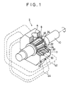
- a rotary valve apparatus which comprises a rotor housing 2.
- the rotor housing 2 has a rotor bore defined therein, an inlet 4, and an outlet 6.
- the inlet 4 and the outlet 6 are located above and below, respectively.
- the outlet 6 is not shown in Fig. 1.
- a rotor 8 is contained for rotation in the rotor bore of the rotor housing 2.
- the rotor 8 has a rotor shaft 10, both ends of which are rotatably supported on the rotor housing 2.
- the housing 2 includes a housing body 3 surrounding the rotor 8 and a pair of end walls 12 on either side of the body 3. These end walls 12 define a pair of side chambers 18 and 20 on either side of the rotor 8, in the rotor housing 2.
- the opposite ends of the rotor shaft 10 are supported individually on the end walls 12 by means of their corresponding bearings 14 for rotation and axial displacement.
- a seal 16 is interposed between each end wall 12 and the rotor shaft 10 so as to be situated nearer to the rotor 8 than its corresponding bearing 14 is.
- the seals 16 serve to keep their corresponding side chambers 18 and 20 airtight.
- One end of the rotor shaft 10 is connected to a drive source (not shown), and the rotor 8 is rotated in one direction at a constant speed by the drive source.
- the rotor 8 is tapered, and has a plurality of pockets 22 formed on its outer peripheral surface. These pockets 22 are arranged at intervals in the circumferential direction of the rotor 8. Also, a plurality of vane seals 24 are attached to the outer peripheral surface of the rotor 8. Each vane seal 24 is located between each two adjacent pockets 22.
- a liner 26 is mounted on the inner surface of the housing body 3. As the rotor 8 rotates, the vane seals 24 move in sliding contact with the liner 26. A pair of side seals 28 are attached individually to small- and large-diameter ends of the rotor 8. The seals 28 are connected individually to the opposite ends of each vane seal 24 in an airtight manner. As the rotor 8 rotates, moreover, the side seals 28 move airtightly in sliding contact with the liner 26 of the housing body 3. Thus, the pockets 22 of the rotor 8 are defined airtightly by the vane seals 24, liner 26, and side seals 28.
- the side chambers 18 and 20 are connected to a pressure source through their corresponding passages which extend in the rotor housing 2. Thus, the chambers 18 and 20 can be supplied with pressure from the pressure source. The pressure in each side chamber is adjusted to the maximum pressure supplied to the pockets 22.
- the large-diameter end of the rotor 8 has an effective pressure bearing area larger than that of the small-diameter end. Accordingly, when the pressures in the side chambers 18 and 20 act on the small- and large-diameter ends of the rotor 8, the rotor 8 is subjected to a force directed to the small-diameter end side. Even if the vane seals 24 and the side seals 28 are worn, therefore, their sealing performance can be maintained by allowing the rotor 8 to shift its position toward the small-diameter end side.
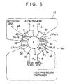
- the pockets 22 on the outer peripheral surface of the rotor 8 are 12 in number, for example. In this case, therefore, the pockets 22 are arranged at regular intervals of 30° on the rotor surface.
- the rotor housing 2 shown Fig. 3 is different in shape from the one shown in Fig. 1, this is intended for ease of illustration only. More specifically, the rotor housing 2 may be formed having any desired external shape, and is only expected to have a tapered bore which can contain the rotor 8 for rotation therein.
- the inlet 4 and the outlet 6 of the rotor housing 2 are separated in the diametrical direction of the rotor 8.
- the inlet 4 is open to the low-pressure side or the atmosphere, and the outlet 6 is connected to the high-pressure side or a high-pressure container (not shown).
- the rotor 8 is rotated in the clockwise direction indicated by the arrow in Fig. 3.
- Two communication ports 30 and 32 and a pressure-regulating port 34 are formed successively in that portion of the wall of the rotor housing 2 which extends from the inlet 4 to the outlet 6 with respect to the rotating direction of the rotor 8.
- two communication ports 36 and 38 and a pressure-regulating port 40 are formed successively in that portion of the housing wall which extends from the outlet 6 to the inlet 4.
- One end of each of these ports penetrates the liner 26 and opens into the rotor housing 2.
- a screen 41 is attached to the open end portion of each port.
- the screen 41 has a meshed structure, and its mesh size is smaller enough than a material supplied to each pocket 22.
- Each of the distances between the respective open ends of the communication ports 30 and 32, between those of the communication port 32 and the pressure-regulating port 34, between those of the communication ports 36 and 38, and between those of the communication port 38 and the pressure-regulating port 40 is equal to the distance between each two adjacent vane seals 24, with respect to the rotating direction of the rotor 8. More specifically, the pressurization-side ports 30, 32 and 34 situated between the inlet 4 and the outlet 6, with respect to the rotating direction of the rotor 8, are arranged at regular intervals of 30° in the circumferential direction of the rotor 8. Likewise, the depressurization-side ports 36, 38 and 40 situated between the outlet 6 and the inlet 4 are arranged at regular intervals of 30° in the circumferential direction of the rotor 8.
- each pocket 22 cannot be connected simultaneously to two adjacent ports on the pressurization or depressurization side during the rotation of the rotor 8.
- the pressurization-side ports 30, 32 and 34 and their corresponding depressurization-side ports 36, 38 and 40 are arranged symmetrically with respect to a vertical plane which connects the inlet 4 and the outlet 6 of the rotor housing 2.
- the arrangement of the ports 30 to 40 is not symmetrical with respect to a horizontal plane which contains the axis of the rotor 8.
- the communication ports 32 and 38 are displaced toward the inlet 4 by a predetermined angle a (e.g., 5° ) from the aforesaid horizontal plane, as shown in Fig. 3.
- a e.g. 5°
- the pressurization-side ports 30, 32 and 34 are closed individually by the vane seals 24 of the rotor 8, therefore, the depressurization-side ports 36, 38 and 40 are connected to their corresponding pockets 22.
- the communication ports 30 and 38 are connected to each other by means of an equalizing pipe 42, and the communication ports 32 and 36 are also connected to each other by means of an equalizing pipe 44.
- the pressure-regulating port 40 on the inlet side is connected to a recovery tank, which shares the pressure with the inlet 4, by means of a connecting pipe 46, and the pressure-regulating port 34 on the outlet side is connected to the aforesaid high-pressure container by means of a connecting pipe 48.
- the recovery tank is connected to the high-pressure container through a booster (not shown).
- each of the ports 30, 32, 34, 36, 38 and 40 has its own counterpart, so that each of the equalizing pipes 42 and 44 also has one.
- Each pair of ports are spaced in the axial direction of the rotor 8, and can communicate with the pockets 22.
- a cooling passage 5 is formed in the body 3 of the rotor housing 2.
- the pressure in the high-pressure container is P H in terms of the gauge pressure
- the pressure P H is continually supplied to the outlet 6. Since the inlet 4 is open to the atmosphere, as mentioned before, the pressure in the inlet 4 is always 0 in terms of the gauge pressure. Accordingly, the internal pressure of the pocket 22 connected to the outlet 6 is P H , while that of the pocket 22 connected to the inlet 4 is 0.
- the valve apparatus is provided with the equalizing pipes 42 and 44.
- the rotor 8 rotates, therefore, one pocket 22 which moves from the outlet 6 toward the inlet 4 communicates with another pocket 22 which moves from the inlet 4 toward the outlet 6, by means of the corresponding equalizing pipe and communication ports, whereupon the respective internal pressures of the two pockets 22 become equal.
- the internal pressure of the pocket 22 moving from the outlet 6 toward the inlet 4 is reduced by stages, and in contrast with this, that of the pocket 22 moving from the inlet 4 toward the outlet 6 is increased by stages.
- each depressurization-side pocket 22 moving from the outlet 6 toward the inlet 4 is subjected to two cycles of depressurization for each equalizing pipe, while each pressurization-side pocket 22 moving from the inlet 4 toward the outlet 6 is subjected to two cycles of pressurization for each equalizing pipe.
- each depressurization-side pocket 22 communicates with two of the pressurization-side pockets 22 by means of one and the same equalizing pipe, while each pressurization-side pocket 22 also communicates with two of the depressurization-side pockets 22 by means of the same equalizing pipe.
- Each depressurization-side pocket 22 is connected to the pressure-regulating port 40 before it is connected to the inlet 4, and each pressurization-side pocket 22 is connected to the pressure-regulating port 34 before it is connected to the outlet 6.
- each depressurization-side pocket 22 is subjected to five cycles of depressurization in total as it moves from the outlet 6 to the inlet 4, and each pressurization-side pocket 22 is also subjected to five cycles of pressurization in total as it moves from the inlet 4 to the outlet 6.
- the pressure in each depressurization-side pocket 22 is reduced in five stages of depressurization, while the pressure in each pressurisation-side pocket 22 is increased in five stages of pressurization.
- depressurization-side pockets 22 D2 and 22 D3 which follow the pocket 22 D1 , with respect to the rotating direction of the rotor 8, are connected to the communication ports 38 and 36, respectively.
- pressurization-side pockets 22 U2 and 22 U3 which follow the pocket 22 U1 are connected to the communication ports 32 and 30, respectively.
- the pockets 22 D2 and 22 D3 communicate with the pockets 22 U3 and 22 U2 by means of the equalizing pipes 42 and 44, respectively, so that the respective internal pressures of the depressurization-and pressurization-side pockets 22 communicating with one another are equalized.
- the pocket 22 U3 communicates with the pocket 22 D1 by means of the equalizing pipe 42 immediately before it starts to communicate with the pocket 22 D2 by means of the same equalizing pipe 42. Accordingly, the internal pressure of the pocket 22 U3 is increased from 0 to P H /5, the same level as that of the pocket 22 D1 , immediately before the pocket 22 U3 is connected to the pocket 22 D2 .
- the pocket 22 U3 communicates again with the pocket 22 D2 by means of the same equalizing pipe 42, thereafter, its internal pressure is further increased. More specifically, the internal pressure of the pocket 22 U3 is increased from P H /5 to 2P H /5. This indicates that the internal pressure of the pocket 22 D2 is reduced from 3P H /5 to 2P H /5.
- the pocket 22 U2 Immediately before the pocket 22 U2 starts to communicate with the pocket 22 D3 by means of the equalizing pipe 44, it communicates with the pocket 22 D2 by means of the same equalizing pipe 44, so that the internal pressure of the pocket 22 U2 is on the same level as that of the pocket 22 D2 .
- the pocket 22 U2 communicates again with the pocket 22 D3 by means of the equalizing pipe 44, thereafter, its internal pressure is increased from 3P H /5 to 4P H /5, while the internal pressure of the pocket 22 D3 is reduced from P H to 4P H /5.
- the depressurization-side pocket 22 D3 communicates with the pressurization-side pocket 22 U3 by means of the equalizing pipe 44, and the pocket 22 D2 communicates with the pressurization-side pocket 22 U4 , which directly follows the pocket 22 U3 , by means of the equalizing pipe 42.
- the pockets 22 D2 and 22 D3 are subjected again to depressurization through the same equalizing pipes 42 and 44, respectively, while the pocket 22 U3 is subjected again to pressurization.
- the respective internal pressures of the pockets 22 D2 and 22 D3 are reduced from 2P H /5 to P H /5 and from 4P H /5 to 3P H /5, respectively.
- the respective internal pressures of the pockets 22 U3 and 22 U4 are increased from 2P H /5 to 3P H /5 and from 0 to P H /5, respectively.
- the pocket 22 U2 which precedes the pocket 22 U3 is connected to the pressure-regulating port 34, and its internal pressure is increased from 4P H /5 to P H .
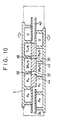
- FIGs. 9, 10 and 11 illustrate the valve apparatus in an expedient form such that the pressurization-side pockets face the depressurization-side pockets, individually.
- the pressurization and depressurization-side pockets are supposed to move straight in opposite directions as the rotor 8 rotates.
- the dashed lines indicate that the pockets repeatedly move from the pressurization side to the depressurization side and from the depressurization side to the pressurization side as the rotor 8 rotates.
- the material supplied through the inlet 4 of the rotor housing 2 is received by that pocket 22 which is connected to the inlet 4. Since the internal pressure of the pocket 22 connected to the inlet 4 is equal to the atmospheric pressure, the material can be smoothly fed through the inlet 4 into the pocket 22.
- each pocket 22 In the process of transportation of the material, the internal pressure of each pocket 22 is increased by stages, as mentioned before, and becomes equal to the pressure in the outlet 6 immediately before the outlet 6 is reached.
- the pocket 22 having received the material is connected to the outlet 6, therefore, the material is fed from the pocket 22 into the high-pressure container through the outlet 6 by gravity.
- the empty pocket 22, having passed the outlet 6, moves toward the inlet 4.
- the internal pressure of the pocket 22 is reduced by stages to the level of the atmospheric pressure, and the pocket 22 is connected again to the inlet 4.
- each pocket 22 of the valve apparatus is subjected to five cycles of pressure equalization in each of the processes of movement from the inlet 4 to the outlet 6 and from the outlet 6 to the inlet 4 by means of the two equalizing pipes 42 and 44. Accordingly, the pressure released from each depressurization-side pocket 22 D to the recovery tank side through the pressure-regulating port 40, that is, the gas recovery pressure, can be reduced from P H to P H /5, as mentioned before.
- each pressurization-side pocket 22 U communicates with only one depressurization-side pocket 22 D by means of each equalizing pipe as the rotor 8 rotates
- each pressurization- or depressurization-side port is subjected to only three cycles of pressure equalization in total. In this case, therefore, the recovery pressure can be reduced only from P H to P H /3.
- the recovery pressure can be reduced to 3/5 of that for the conventional valve apparatus.
- the supply pressure applied to each pocket 22 through the pressure-regulating port 34 is reduced to 3/5 of that for the conventional apparatus.
- the loss of the pressure supplied from the high-pressure container side that is, the rate of gas flow through the apparatus, can be reduced substantially, so that the loads on the recovery tank and the booster can be lightened considerably.
- each pressurization-side pocket is connected to each depressurization-side pocket through each equalizing pipe, or when each pressurization-side pocket is connected to the pressure-regulating port 34, moreover, the differential pressure between the connected portions can be made lower than in the conventional case.
- each pressurization-side port is opened, therefore, the impact of the gas flow acting on each corresponding vane seal can be reduced.
- Table 1 below shows changes of pressure in the equalizing pipes 42 and 44 observed when the valve apparatus is operated with use of various capacity ratios between the pipes 42 and 44 and each pocket 22.
- Vk and Vp represent the capacity of each equalizing pipe and that of each pocket 22, respectively, and the numerical values are given in terms of the gauge pressure.
- the pressure in the connecting pipe 48 is 15 kg/cm 2 , which indicates that the pressure in the high-pressure container is kept at this value.
- the equalizing pipes 42 and 44 are utilized individually for the two cycles of pressure equalization for each pressurization- or depressurization-side pocket 22, so that their respective internal pressures change in two stages.
- the pressure in the pipe 42 takes a value P1 or P2
- the pressure in the pipe 44 takes a value P3 or P4.
- the pressures P H /5 and 2P H /5 alternately develop in the equalizing pipe 42.
- the capacity ratio Vk/Vp is 0.5
- P H /5 is 3.46 kg/cm 2
- 2P H /5 is 5.77 kg/cm 2
- the pressures 3P H /5 and 4P H /5 alternately develop in the equalizing pipe 44.
- 3P H /5 is 9.23 kg/cm 2
- 4P H /5 is 11.54 kg/cm 2 .
- Table 1 also shows changes of pressure in the equalizing pipes 42 and 44 observed when the capacity ratio Vk/Vp is 0, that is, when the capacity of each equalizing pipe is 0, and pressures in the equalizing pipes obtained when each equalizing pipe is used in one cycle of pressure equalization for each pocket, as in the conventional case.
- the present invention is not limited to the embodiment described above, and that various changes and modifications may be effected therein by one skilled in the art without departing from the scope or spirit of the invention.
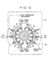
- the number of the equalizing pipes is not limited to two, and may alternatively be one or three or more.
- valve apparatus is used to feed the material from the lower-pressure side, e.g., atmosphere side, toward the high-pressure container.
- the apparatus may be used to discharge the material from the high-pressure container to the low-pressure side.
- the valve apparatus of Fig. 3 is arranged upside down so that the outlet 6 on the lower side is open to the atmosphere, and the depressurization- and pressurization-side communication ports 38 and 32 are displaced by an angle a toward the outlet 6 from a horizontal plane which contains the axis of the rotor 8.
Landscapes
- Engineering & Computer Science (AREA)
- Mechanical Engineering (AREA)
- General Engineering & Computer Science (AREA)
- Multiple-Way Valves (AREA)
- Filling Or Emptying Of Bunkers, Hoppers, And Tanks (AREA)
Claims (7)
- Drehventilvorrichtung mit einem Rotorgehäuse (2), das eine darin definierte Rotorbohrung aufweist, einem mit der Hoch- oder Niederdruckseite verbindbaren Einlass (4), einem von dem Einlass (4) in der Umfangsrichtung der Rotorbohrung getrennten Auslass (6), der mit der anderen Druckseite verbindbar ist (6), wobei einer erster Kommunikationsport (30) in einem ersten Bereich angeordnet ist, der vom Einlass (4) zum Auslass (6) verläuft, und ein zweiter Kommunikationsport (38) in einem zweiten Bereich angeordnet ist, der vom Auslass (6) zum Einlass (4) verläuft, und zwar bezüglich der Umfangsrichtung der Rotorbohrung, wobei jeder Kommunikationsport (30,38) ein erstes, sich in die Rotorbohrung öffnendes Ende und ein zweites Ende aufweist, einer Verbindungseinrichtung (42) zum Verbinden der zweiten Enden der ersten und zweiten Kommunikationsports (30, 38), miteinander, einem drehbar in die Rotorbohrung des Rotorgehäuses (2) eingepassten Rotor (8), wobei der Rotor (8) eine Achse, eine äußere peripherische Oberfläche und eine Vielzahl von Taschen (22, 22U, 22D), die unter regelmäßigen Intervallen in der Umfangsrichtung auf der äußeren peripherischen Oberfläche angeordnet sind, aufweist, wobei die Taschen (22) derart gestaltet sind, dass sie zur Verbindung mit dem Einlass (4), dem Auslass (6) und dem ersten Ende jedes Kommunikationsports (30, 38) individuell bewegbar sind, wenn sich der Rotor (8) dreht, einer ersten Versorgungseinrichtung (40, 46) zum Versorgen jeder Tasche (22) mit einem Druck gleich einem Druck im Einlass (4), unmittelbar bevor die Tasche (22) mit dem Einlass (4) verbunden ist, wenn sich der Rotor (8) dreht, und einer zweiten Versorgungseinrichtung (34, 48) zum Versorgen jeder Tasche (22) mit einem Druck gleich einem Druck im Auslass (6), unmittelbar bevor die Tasche (22) mit dem Auslass (6) verbunden ist, wenn sich der Rotor (8) dreht,wobei die Vorrichtung weiterhin mehrere Stufenausgleichseinrichtungen einschließlich der ersten und zweiten Kommunikationsports (30, 38) und der Verbindungseinrichtung (42) aufweist, die es ermöglichen, dass sich jede Tasche (22, vom Einlass (4) zum Auslass (6) bewegt, so dass sie aufeinanderfolgend durch die Verbindungseinrichtung (42) und die ersten und zweiten Kommunikationsporte (38) mit jeder ersten und zweiten Tasche (22D), die sich aufeinanderfolgend vom Auslass (6) zum Einlass (4) bewegen, wenn sich der Rotor (8) dreht, verbunden ist,wobei zu der Vorrichtung weiter gehören eine Dichtungseinrichtung (24, 26, 28) zum luftdichten Abdichten der Taschen (22) des Rotors im Zusammenwirken mit der Innenoberfläche der Rotorbohrung, wobei zu der Dichtungseinrichtung ein auf der Innenoberfläche des Rotorgehäuses (2) montierter Einsatz bzw. Abstreifer (26) gehört, Lippendichtung (24), die an dem Außenumfangsrand des Rotors () in einer Stellung zwischen zwei benachbarten Taschen (22) angebracht sind und ein paar Seitendichtungen (28), die jeweils an den beiden Enden des Rotors (8) angebracht und mit den Enden der Lippendichtungen (24) in einer luftdichten Weise verbunden sind, und wobei der erste und zweite Kommunikationsport (30, 38) und die Lippendichtungen (249 derart angeordnet sind, dass dann, wenn der erste Kommunikationsport (30) durch eine der Lippendichtungen (24) geschlossen ist, der zweite Kommunikationsport (38) mit einer der Taschen (22) verbunden ist; undwobei das Rotorgehäuse (2) weiterhin ein Paar von Seitenkammern (18, 20) aufweist, die individuell auf beiden Seiten des Rotors (8) bezüglich der axialen Richtung des Rotors (8) definiert sind und einem vorbestimmten Druck unterliegen, dass die Rotorbohrung und der Rotor (8) abgeschrägt sind, und dass der Rotor (8) zur Verschiebung in der axialen Richtung gelagert ist und eine Endfläche mit einem kleinen Durchmesser aufweist, welche dem Druck von einer der Seitenkammern (18, 20) unterliegt, sowie eine Endfläche mit großem Durchmesser aufweist, welche einen Druckaufnahmebereicht aufweist, der größer als der der Endflächen mit dem kleinen Durchmesser ist und der dem Druck von der anderen Seitenkammer unterliegt.
- Vorrichtung nach Anspruch 1,
dadurch gekennzeichnet,
dass die mehreren Stufenausgleichseinrichtungen durch eine Anordnung der ersten und zweiten Kommunikationsportes(30, 38) in der Weise, dass die ersten und zweiten Taschen (22D), die sich aufeinanderfolgend vom Auslass (6) zum Einlass (4) bewegen, aufeinanderfolgend mit einem der ersten und der zweiten Kommunikationsports (30, 38) verbunden sind, während eine der Taschen (22U), die sich vom Einlass (4) zum Auslass (6) bewegt, mit dem anderen der ersten und zweiten Kommunikationsports (30, 38) verbunden ist, wenn sich der Rotor 88) dreht, gebildet ist. - Vorrichtung nach Anspruch 1 oder 2,
dadurch gekennzeichnet,
dass das Paar von Seitenkammern (18, 20) mit einem Druck gleich dem maximalen Druck, der den Taschen (22) des Rotors (8) zugeführt wird, versorgt wird. - Vorrichtung nach Anspruch 1, 2 oder 3,
dadurch gekennzeichnet,
dass jeder der ersten und zweiten Kommunikationsports (30, 38) einen Maschenschirm (41) in sich aufweist. - Vorrichtung nach einem der vorangehenden Ansprüche,
dadurch gekennzeichnet,
dass die erste Versorgungseinrichtung einen ersten Druckregelungsport (40) aufweist, der im Rotorgehäuse (2) gebildet ist, wobei der erste Druckregelungsport (40) ein mit der Druckseite der Hoch- und Niederdruckseiten verbundenes Ende und ein anderes mit den Taschen (22) des Rotors (8) verbindbares Ende aufweist, und dass die zweite Versorgungseinrichtung einen zweiten Druckregelungsport (34) aufweist, der in dem Rotorgehäuse (2) gebildet ist, wobei der zweite Druckregelungsport 834) ein mit der anderen Druckseite der Hoch- und Niederdruckseiten verbundenes Ende und ein anderes ende mit den Taschen (22) des Rotors (8) verbindbares Ende aufweist. - Vorrichtung nach einem der vorangehenden Ansprüche,
dadurch gekennzeichnet,
die Verbindungseinrichtung eine Ausgleichsröhre (42) zum Verbinden der jeweiligen anderen Enden der ersten und zweiten Kommunikationsports (30, 38) aufweist. - Vorrichtung nach einem der vorangehenden Ansprüche,
dadurch gekennzeichnet,
dass das Rotorgehäuse (2) weiterhin dritte und vierte Kommunikationsports (32, 36) aufwiest, die jeweils im ersten und zweiten Bereich des Rotorgehäuses (2) angeordnet sind, und dass weiterhin eine zweite Verbindungseinrichtung (44) zum Verbinden der dritten und vierten Kommunikationsports (32, 36) miteinander einschließlich der dritten und vierten Kommunikationsports (32, 36) und der zweiten Verbindungseinrichtung vorgesehen sind, sowie mehrere zweite Ausgleichseinrichtungen, die es ermöglichen, dass jede Tasche, die sich vom Einlass (4) zum Auslass (6) bewegt, aufeinanderfolgend durch die zweite Verbindungseinrichtung (44) und die dritten und vierten Kommunikationsports (32, 36) mit jeder der ersten und zweiten Taschen, die sich aufeinanderfolgend vom Auslass (6) zum Einlass (4) bewegen, wenn sich der Rotor (8) dreht, verbunden ist.
Applications Claiming Priority (3)
| Application Number | Priority Date | Filing Date | Title |
|---|---|---|---|
| JP9080/93 | 1993-01-22 | ||
| JP908093 | 1993-01-22 | ||
| JP00908093A JP3169463B2 (ja) | 1993-01-22 | 1993-01-22 | ロータリバルブ |
Publications (3)
| Publication Number | Publication Date |
|---|---|
| EP0607964A1 EP0607964A1 (de) | 1994-07-27 |
| EP0607964B1 EP0607964B1 (de) | 1997-06-18 |
| EP0607964B2 true EP0607964B2 (de) | 2001-01-24 |
Family
ID=11710640
Family Applications (1)
| Application Number | Title | Priority Date | Filing Date |
|---|---|---|---|
| EP94100790A Expired - Lifetime EP0607964B2 (de) | 1993-01-22 | 1994-01-20 | Zellenradschleuse |
Country Status (8)
| Country | Link |
|---|---|
| US (1) | US5544995A (de) |
| EP (1) | EP0607964B2 (de) |
| JP (1) | JP3169463B2 (de) |
| KR (1) | KR0142040B1 (de) |
| CN (1) | CN1062063C (de) |
| CA (1) | CA2113962A1 (de) |
| DE (1) | DE69403818T3 (de) |
| RU (1) | RU2120080C1 (de) |
Families Citing this family (39)
| Publication number | Priority date | Publication date | Assignee | Title |
|---|---|---|---|---|
| DE19509229A1 (de) * | 1995-03-17 | 1996-09-19 | Brieden & Co Maschf K | Verfahren und Vorrichtung zum Abdichten von Dampftrocknern bei der Trocknung von Reibungsverschleiß erzeugendem Gut |
| US5823401A (en) * | 1996-02-05 | 1998-10-20 | Zgoda; Roy F. | Sampling and dispensing ball-valve |
| CN1094581C (zh) | 1996-04-04 | 2002-11-20 | 童夏民 | 一种空调机 |
| US5772081A (en) * | 1996-06-04 | 1998-06-30 | Food Industry Research And Development Institute | Low leakage rotary valve |
| DE19801747C1 (de) * | 1998-01-20 | 1999-04-22 | Waeschle Maschf Gmbh | Entlüftungsöffnung für Zellenradschleuse |
| EP1344732A1 (de) * | 2002-03-01 | 2003-09-17 | Kurt Ing. Baier | Einrichtung zur Minimierung des Gasflusses durch Zellradschleusen |
| US6966466B2 (en) * | 2003-11-07 | 2005-11-22 | Asj Holding Aps | Rotary airlock valve |
| EP1709304A1 (de) * | 2004-01-28 | 2006-10-11 | Bishop Innovation Pty. Limited | Öffnungsanordnung für einen drehschiebermotor |
| DE102004012663A1 (de) * | 2004-03-16 | 2005-10-06 | Applied Films Gmbh & Co. Kg | Anlage zum Beschichten von Hohlkörpern, insbesondere von Kunststoffflaschen, mit einem Hochvakuumbereich und einer Schleuse |
| US7757903B2 (en) * | 2006-10-20 | 2010-07-20 | Flsmidth A/S | Feeder assembly for bulk solids |
| RU2329101C2 (ru) * | 2007-04-04 | 2008-07-20 | Леонид Федорович Порядков | Вентиль |
| JP5091554B2 (ja) * | 2007-06-19 | 2012-12-05 | 三井造船株式会社 | 原料投入装置 |
| ITFI20080121A1 (it) * | 2008-06-30 | 2010-01-01 | Saeco Ipr Ltd | "dispositivo di separazione tra ambienti diversi e di dosaggio di un prodotto alimentare e macchina incorporante detto dispositivo" |
| JP4742162B2 (ja) * | 2009-07-14 | 2011-08-10 | 株式会社三友金属 | ブラスト装置 |
| US20110049198A1 (en) * | 2009-08-26 | 2011-03-03 | Battelle Energy Alliance, Llc | Rotary feeders, rotor assemblies for rotary feeders and related methods |
| AT509953B1 (de) * | 2010-05-21 | 2012-06-15 | Kwb Kraft Und Waerme Aus Biomasse Gmbh | Zellenradschleuse |
| US8464860B2 (en) * | 2010-09-21 | 2013-06-18 | General Electric Company | System for thermally controlling a solid feed pump |
| DE102012206590A1 (de) * | 2012-04-20 | 2013-10-24 | Coperion Gmbh | Verfahren zum Betrieb einer Zellenradschleuse sowie Zellenradschleuse zur Durchführung des Verfahrens |
| US9863545B2 (en) * | 2012-07-11 | 2018-01-09 | Keiichi Kawamura | Hose coupling device, mop suction device, electric vacuum cleaner, and ball valve |
| CN103363292B (zh) * | 2013-07-22 | 2015-04-08 | 广州龙之杰科技有限公司 | 可精确控制的分气气罐装置 |
| CN105016032B (zh) * | 2014-04-15 | 2018-07-20 | 藤原酿造机械株式会社 | 立式旋转阀 |
| CN104747773B (zh) * | 2015-03-16 | 2017-02-22 | 西安交通大学 | 一种流量可调的单边板式三位四通转阀 |
| CN104806592B (zh) * | 2015-03-16 | 2016-11-30 | 西安交通大学 | 一种流量可调的双边板式三位四通转阀 |
| CN105059843A (zh) * | 2015-08-03 | 2015-11-18 | 中冶焦耐工程技术有限公司 | 一种叶轮给料机助力给料方法及结构 |
| CN105173743B (zh) * | 2015-10-27 | 2018-08-03 | 哈尔滨电站设备成套设计研究所有限公司 | 滚筒式给料机、工作及密封方法 |
| RU2718102C2 (ru) * | 2016-01-18 | 2020-03-30 | Евгений Игоревич Казанцев | Пробковый кран |
| CN106429525B (zh) * | 2016-12-14 | 2019-03-26 | 张海娟 | 一种流量可控的阀门 |
| US20190039836A1 (en) * | 2017-08-01 | 2019-02-07 | Larry Baxter | Solids Conveyance across Pressure Gradients using Pistons in Rotating Disks |
| DE102018113871A1 (de) * | 2018-06-11 | 2019-12-12 | Bma Braunschweigische Maschinenbauanstalt Ag | Zellenradschleuse und Verfahren zum Betreiben einer Zellenradschleuse |
| KR102808034B1 (ko) * | 2019-01-18 | 2025-05-15 | 트리코야 테크놀러지스 엘티디 | 제1 가스 압력의 제1 환경으로부터 제2 가스 압력의 제2 환경으로 고체 입자를 전달하기 위한 시스템 및 방법 |
| US11656113B2 (en) * | 2019-07-19 | 2023-05-23 | Agra Industries, Inc. | Bulk material metering system |
| IT201900019088A1 (it) * | 2019-10-16 | 2021-04-16 | La Marzocco Srl | Tramoggia per macchina macina caffè dotata di dispositivo di chiusura inferiore salva chicchi e macchina macina caffè dotata di tale tramoggia |
| CN111165864B (zh) * | 2020-02-17 | 2021-09-28 | 龙岩烟草工业有限责任公司 | 喂料机及其控制方法和烟丝生产设备 |
| CN111591556B (zh) * | 2020-06-06 | 2021-08-31 | 江苏金城建设有限公司 | 一种基建工地用装钢管装置 |
| CN111781303B (zh) * | 2020-07-01 | 2023-02-10 | 深圳市步锐生物科技有限公司 | 一种手持式呼出气采集多参数分类采集机构 |
| CN115492962A (zh) * | 2021-06-17 | 2022-12-20 | 浙江盾安机械有限公司 | 四通阀及具有其的空调系统 |
| CN116409634A (zh) * | 2021-12-29 | 2023-07-11 | 中国石油化工股份有限公司 | 聚丙烯颗粒水力输送转料器 |
| CN118654148B (zh) * | 2024-08-20 | 2024-10-25 | 云南嘉瑞华新能源科技有限公司 | 一种烟叶烘干设备用通风阀门 |
| CN119821952B (zh) * | 2025-02-27 | 2025-06-27 | 徐州力优智能科技有限公司 | 一种混凝土喷浆机用自密封补偿式卸料器 |
Citations (6)
| Publication number | Priority date | Publication date | Assignee | Title |
|---|---|---|---|---|
| DE660877C (de) † | 1936-08-14 | 1938-06-04 | Dipl Berging Arnold Roemer | Einschleusvorrichtung mit Zellenrad fuer Druckfoerderanlagen |
| DE843384C (de) † | 1943-06-04 | 1952-07-07 | Karl Brieden | Einschleusvorrichtung fuer Druckluftfoerderanlagen, besonders fuer Blasversatz, mit Stopfbuechsendichtung an den Zellenradstirnseiten |
| US3556355A (en) † | 1968-05-28 | 1971-01-19 | Basic Inc | Pressure sealed rotary feeder |
| US3610476A (en) † | 1969-08-06 | 1971-10-05 | Bauer Bros Co | Rotary valve |
| DE2845261A1 (de) † | 1978-10-18 | 1979-10-31 | Baumasch Handel Serv Ersatz | Vorrichtung zum foerdern und/oder zuteilen von materialien |
| DD277445A1 (de) † | 1988-11-29 | 1990-04-04 | Ardenne Forschungsinst | Vakuum-zellenradschleuse |
Family Cites Families (9)
| Publication number | Priority date | Publication date | Assignee | Title |
|---|---|---|---|---|
| US2858212A (en) * | 1956-02-13 | 1958-10-28 | Condi Engineering Corp | Wood chip feeders |
| US2933208A (en) * | 1957-12-18 | 1960-04-19 | Spront Waldron & Company Inc | Pulp manufacture |
| US3612307A (en) * | 1969-01-28 | 1971-10-12 | Clarence W Vogt | Feeder and liner assembly therefor |
| US3633797A (en) * | 1970-06-24 | 1972-01-11 | Russell M Graff | Rotary valves |
| CA1110095A (en) * | 1979-11-28 | 1981-10-06 | Luaaron Metals Ltd. | Rotary charger |
| US4397657A (en) * | 1982-04-19 | 1983-08-09 | Allis-Chalmers Corporation | Gas lock system charging particles into a pressurized gasification reactor |
| CA1328064C (en) * | 1987-07-27 | 1994-03-29 | Masao Kobari | Apparatus for expanding material for foodstuffs, favorite items and the like |
| US5044837A (en) * | 1989-09-14 | 1991-09-03 | Phillips Petroleum Company | Method and apparatus for continuously feeding particulate solid material into a pressurized system without pressure loss |
| DE4218094A1 (de) * | 1991-06-04 | 1992-12-10 | Liezen Maschf | Zellradschleuse |
-
1993
- 1993-01-22 JP JP00908093A patent/JP3169463B2/ja not_active Expired - Fee Related
-
1994
- 1994-01-20 DE DE69403818T patent/DE69403818T3/de not_active Expired - Fee Related
- 1994-01-20 EP EP94100790A patent/EP0607964B2/de not_active Expired - Lifetime
- 1994-01-21 US US08/183,758 patent/US5544995A/en not_active Expired - Fee Related
- 1994-01-21 CA CA002113962A patent/CA2113962A1/en not_active Abandoned
- 1994-01-21 RU RU94001559A patent/RU2120080C1/ru not_active IP Right Cessation
- 1994-01-22 KR KR1019940001143A patent/KR0142040B1/ko not_active Expired - Fee Related
- 1994-01-22 CN CN94101211A patent/CN1062063C/zh not_active Expired - Fee Related
Patent Citations (6)
| Publication number | Priority date | Publication date | Assignee | Title |
|---|---|---|---|---|
| DE660877C (de) † | 1936-08-14 | 1938-06-04 | Dipl Berging Arnold Roemer | Einschleusvorrichtung mit Zellenrad fuer Druckfoerderanlagen |
| DE843384C (de) † | 1943-06-04 | 1952-07-07 | Karl Brieden | Einschleusvorrichtung fuer Druckluftfoerderanlagen, besonders fuer Blasversatz, mit Stopfbuechsendichtung an den Zellenradstirnseiten |
| US3556355A (en) † | 1968-05-28 | 1971-01-19 | Basic Inc | Pressure sealed rotary feeder |
| US3610476A (en) † | 1969-08-06 | 1971-10-05 | Bauer Bros Co | Rotary valve |
| DE2845261A1 (de) † | 1978-10-18 | 1979-10-31 | Baumasch Handel Serv Ersatz | Vorrichtung zum foerdern und/oder zuteilen von materialien |
| DD277445A1 (de) † | 1988-11-29 | 1990-04-04 | Ardenne Forschungsinst | Vakuum-zellenradschleuse |
Non-Patent Citations (1)
| Title |
|---|
| Brochure No 2820, "High Pressure Rotary Valves", Sprout-Bauer, 1989 † |
Also Published As
| Publication number | Publication date |
|---|---|
| JP3169463B2 (ja) | 2001-05-28 |
| CN1062063C (zh) | 2001-02-14 |
| KR940018592A (ko) | 1994-08-18 |
| CA2113962A1 (en) | 1994-07-23 |
| EP0607964B1 (de) | 1997-06-18 |
| DE69403818D1 (de) | 1997-07-24 |
| CN1098487A (zh) | 1995-02-08 |
| DE69403818T2 (de) | 1998-01-15 |
| RU2120080C1 (ru) | 1998-10-10 |
| DE69403818T3 (de) | 2001-07-19 |
| EP0607964A1 (de) | 1994-07-27 |
| KR0142040B1 (ko) | 1998-07-15 |
| US5544995A (en) | 1996-08-13 |
| JPH06221449A (ja) | 1994-08-09 |
Similar Documents
| Publication | Publication Date | Title |
|---|---|---|
| EP0607964B2 (de) | Zellenradschleuse | |
| AU647617B2 (en) | Gas separation system and gas recovery system | |
| EP0166851B1 (de) | Vakuumpumpe der Schraubenbauart | |
| US4865530A (en) | Scroll-type vacuum apparatus with oil supply to a compression chamber | |
| US6143056A (en) | Rotary valve for two bed vacuum pressure swing absorption system | |
| EP0708889B1 (de) | Schraubenverdichter | |
| US5356275A (en) | Device for supplying a multi-stage dry-running vacuum pump with inert gas | |
| US3833317A (en) | Rotary gear motor/pump having hydrostatic bearing means | |
| JPH0354372A (ja) | 回転式流体圧力装置 | |
| US20120014825A1 (en) | Roots type fluid machine | |
| US6497564B2 (en) | Balanced rotors positive displacement engine and pump method and apparatus | |
| US6390793B1 (en) | Rotary gear pump with fluid inlet size compensation | |
| US3138320A (en) | Fluid seal for compressor | |
| US5061120A (en) | Direction correcting device for shield tunnelling machine | |
| US3178235A (en) | Rotary feeder | |
| JPS6217389A (ja) | 機械ポンプ | |
| CN100383392C (zh) | 装有滚动轴承的轴套式齿轮泵 | |
| EP0183422B1 (de) | Zweisystemige Pumpe mit drei versetzt angeordneten Zahnrädern | |
| EP0018216B1 (de) | Umkehrbare(r) Zahnradpumpe oder -motor und Zwischenscheiben dafür | |
| US3165119A (en) | Four-way valve device | |
| GB2051244A (en) | Rotary positive - displacement fluidmachines | |
| WO1998010194A1 (en) | Reversible venturi-effect pump | |
| US5039258A (en) | Hydraulic transporter with united streaming reversing means | |
| JP4294212B2 (ja) | 高圧スクリュー圧縮装置 | |
| GB2440542A (en) | Vacuum pump gearbox purge gas arrangement |
Legal Events
| Date | Code | Title | Description |
|---|---|---|---|
| PUAI | Public reference made under article 153(3) epc to a published international application that has entered the european phase |
Free format text: ORIGINAL CODE: 0009012 |
|
| AK | Designated contracting states |
Kind code of ref document: A1 Designated state(s): DE FR GB IT |
|
| 17P | Request for examination filed |
Effective date: 19941221 |
|
| 17Q | First examination report despatched |
Effective date: 19960102 |
|
| GRAG | Despatch of communication of intention to grant |
Free format text: ORIGINAL CODE: EPIDOS AGRA |
|
| GRAH | Despatch of communication of intention to grant a patent |
Free format text: ORIGINAL CODE: EPIDOS IGRA |
|
| GRAH | Despatch of communication of intention to grant a patent |
Free format text: ORIGINAL CODE: EPIDOS IGRA |
|
| GRAA | (expected) grant |
Free format text: ORIGINAL CODE: 0009210 |
|
| AK | Designated contracting states |
Kind code of ref document: B1 Designated state(s): DE FR GB IT |
|
| REF | Corresponds to: |
Ref document number: 69403818 Country of ref document: DE Date of ref document: 19970724 |
|
| ET | Fr: translation filed | ||
| PLBI | Opposition filed |
Free format text: ORIGINAL CODE: 0009260 |
|
| 26 | Opposition filed |
Opponent name: WAESCHLE MASCHINENFABRIK GMBH Effective date: 19980206 |
|
| PLBF | Reply of patent proprietor to notice(s) of opposition |
Free format text: ORIGINAL CODE: EPIDOS OBSO |
|
| PLBF | Reply of patent proprietor to notice(s) of opposition |
Free format text: ORIGINAL CODE: EPIDOS OBSO |
|
| PLBF | Reply of patent proprietor to notice(s) of opposition |
Free format text: ORIGINAL CODE: EPIDOS OBSO |
|
| PLAB | Opposition data, opponent's data or that of the opponent's representative modified |
Free format text: ORIGINAL CODE: 0009299OPPO |
|
| R26 | Opposition filed (corrected) |
Opponent name: WAESCHLE GMBH Effective date: 19980206 |
|
| PLAW | Interlocutory decision in opposition |
Free format text: ORIGINAL CODE: EPIDOS IDOP |
|
| PLAW | Interlocutory decision in opposition |
Free format text: ORIGINAL CODE: EPIDOS IDOP |
|
| PUAH | Patent maintained in amended form |
Free format text: ORIGINAL CODE: 0009272 |
|
| STAA | Information on the status of an ep patent application or granted ep patent |
Free format text: STATUS: PATENT MAINTAINED AS AMENDED |
|
| 27A | Patent maintained in amended form |
Effective date: 20010124 |
|
| AK | Designated contracting states |
Kind code of ref document: B2 Designated state(s): DE FR GB IT |
|
| ITF | It: translation for a ep patent filed | ||
| ET3 | Fr: translation filed ** decision concerning opposition | ||
| REG | Reference to a national code |
Ref country code: GB Ref legal event code: IF02 |
|
| PGFP | Annual fee paid to national office [announced via postgrant information from national office to epo] |
Ref country code: GB Payment date: 20040114 Year of fee payment: 11 |
|
| PGFP | Annual fee paid to national office [announced via postgrant information from national office to epo] |
Ref country code: FR Payment date: 20040120 Year of fee payment: 11 |
|
| PGFP | Annual fee paid to national office [announced via postgrant information from national office to epo] |
Ref country code: DE Payment date: 20040130 Year of fee payment: 11 |
|
| PG25 | Lapsed in a contracting state [announced via postgrant information from national office to epo] |
Ref country code: IT Free format text: LAPSE BECAUSE OF NON-PAYMENT OF DUE FEES;WARNING: LAPSES OF ITALIAN PATENTS WITH EFFECTIVE DATE BEFORE 2007 MAY HAVE OCCURRED AT ANY TIME BEFORE 2007. THE CORRECT EFFECTIVE DATE MAY BE DIFFERENT FROM THE ONE RECORDED. Effective date: 20050120 Ref country code: GB Free format text: LAPSE BECAUSE OF NON-PAYMENT OF DUE FEES Effective date: 20050120 |
|
| PG25 | Lapsed in a contracting state [announced via postgrant information from national office to epo] |
Ref country code: DE Free format text: LAPSE BECAUSE OF NON-PAYMENT OF DUE FEES Effective date: 20050802 |
|
| GBPC | Gb: european patent ceased through non-payment of renewal fee |
Effective date: 20050120 |
|
| PG25 | Lapsed in a contracting state [announced via postgrant information from national office to epo] |
Ref country code: FR Free format text: LAPSE BECAUSE OF NON-PAYMENT OF DUE FEES Effective date: 20050930 |
|
| REG | Reference to a national code |
Ref country code: FR Ref legal event code: ST |