EP0607965A2 - Digitaler Ausgabe-Bildsensor und ein mit diesem ausgestatteter Balkenkodierleser - Google Patents
Digitaler Ausgabe-Bildsensor und ein mit diesem ausgestatteter Balkenkodierleser Download PDFInfo
- Publication number
- EP0607965A2 EP0607965A2 EP94100794A EP94100794A EP0607965A2 EP 0607965 A2 EP0607965 A2 EP 0607965A2 EP 94100794 A EP94100794 A EP 94100794A EP 94100794 A EP94100794 A EP 94100794A EP 0607965 A2 EP0607965 A2 EP 0607965A2
- Authority
- EP
- European Patent Office
- Prior art keywords
- image sensor
- bar code
- code reader
- digitizer
- accordance
- Prior art date
- Legal status (The legal status is an assumption and is not a legal conclusion. Google has not performed a legal analysis and makes no representation as to the accuracy of the status listed.)
- Granted
Links
Images


Classifications
-
- G—PHYSICS
- G06—COMPUTING OR CALCULATING; COUNTING
- G06K—GRAPHICAL DATA READING; PRESENTATION OF DATA; RECORD CARRIERS; HANDLING RECORD CARRIERS
- G06K7/00—Methods or arrangements for sensing record carriers, e.g. for reading patterns
- G06K7/10—Methods or arrangements for sensing record carriers, e.g. for reading patterns by electromagnetic radiation, e.g. optical sensing; by corpuscular radiation
- G06K7/10544—Methods or arrangements for sensing record carriers, e.g. for reading patterns by electromagnetic radiation, e.g. optical sensing; by corpuscular radiation by scanning of the records by radiation in the optical part of the electromagnetic spectrum
- G06K7/10821—Methods or arrangements for sensing record carriers, e.g. for reading patterns by electromagnetic radiation, e.g. optical sensing; by corpuscular radiation by scanning of the records by radiation in the optical part of the electromagnetic spectrum further details of bar or optical code scanning devices
- G06K7/10841—Particularities of the light-sensitive elements
Definitions
- the present invention relates to a digital output image sensor for reading a picture, such as a bar code symbol, and a bar code reader which uses the digital output image sensor so as to decode a bar code symbol etc. of products or goods in a POS (point of sales) system etc.
- a digital output image sensor for reading a picture, such as a bar code symbol
- a bar code reader which uses the digital output image sensor so as to decode a bar code symbol etc. of products or goods in a POS (point of sales) system etc.
- a conventional image sensor which is used in a bar code reader for decoding a bar code symbol of goods, produces analog signal responding to quantity of light reflected from the bar code symbol.
- the conventional image sensor which is operated by 12 volts d.c. supply, produces the analog signal when a pulse signal is applied to the conventional image sensor.
- FIG.9 shows the bar code symbol 1, and the analog output signal A of the conventional image sensor which is receiving the light reflected from the bar code symbol 1.
- the conventional bar code reader had circuits of two kinds of voltage systems, that is, a 5-volt operation system and a 12-volt operation system.
- the circuits operated by the 5-volt operation system are a microcomputer, a LED (light emitting diode) as light emitter and an operation circuit for communication to external units of POS systems through a transmission cable.
- the circuits of the 12-volt operation system are the above-mentioned image sensor and a digitizer for converting the analog signal into a two-level digital signal. Therefore, it is necessary to provide a DC-DC converter for converting operation voltage from 5 volts d.c. to 12 volts d.c., and a level converter for adjusting the circuits of the 12-volt operation system to the 5-volt operation system in the conventional bar code reader.
- the conventional image sensor produces an analog signal responding to the quantity of the light reflected from the bar code symbol 1 etc., and the analog signal is deciphered by using the microcomputer.
- the microcomputer is operated by digital signal, an expensive digitizer must be provided with the conventional image sensor in the bar code reader.
- the conventional image sensor is operated by 12 volts d.c. supply, the DC-DC converter and the level converter must be provided in the conventional bar code reader.
- the conventional bar code reader it is necessary to arrange spaces for receiving the digitizer, the DC-DC converter and the level converter in the conventional bar code reader. As a result, the conventional bar code reader must be formed in a large size, and becomes an expensive apparatus. The conventional bar code reader is far from design of electric power saving because the DC-DC converter does not have a conversion efficiency of 100%.
- the conventional bar code reader can be used only in a limited place because the conventional bar code reader communicates through a transmission cable in the POS system.
- An object of the present invention is to provide a digital output image sensor and a bar code reader which uses the digital output image sensor, and which can be manufactured with low cost, in a small size, and can be operated at high conversion efficiency.
- a digital output image sensor in accordance with the present invention comprises
- a bar code reader in accordance with the present invention comprises
- FIG.1 shows a front view of a CCD (charge coupled device) image sensor 3 as the digital output image sensor of the present invention.
- FIG.2 is a side view showing the CCD image sensor 3 of FIG.1.
- FIG.3 shows a bar code symbol 1 and a digitized output signal D which is produced by the CCD image sensor 3 receiving the light reflected from the above-mentioned bar code symbol 1.
- FIG.4 is a circuit diagram of a digitizer circuit 3b for converting a round-edged pulse signal into a two-level digital signal in the CCD image sensor 3.
- the CCD image sensor 3 has two functions of an image sensor 3a and the digitizer circuit 3b (not shown) as a digitizer.
- the image sensor 3a is of a linear type one having 2048 pixels.
- the digitizer circuit 3b converts the round-edged pulse signal from the image sensor 3a into a two-level digital signal as the digital output signal of the CCD image sensor 3.
- the digitizer circuit 3b is formed integrally with the image sensor 3a in one chip as shown in FIGs.1 and 2.
- the CCD image sensor 3 has plural terminals, such as a Vcc terminal 2 and a digital signal output terminal 4.
- the CCD image sensor 3 produces a digital signal D when the CCD image sensor 3 receives the light reflected from the bar code symbol 1.
- FIG.4 shows a circuit as a concrete example of the digitizer circuit 3b.
- the digitizer circuit 3b is integrated with the image sensor 3a in one chip as the CCD image sensor 3.
- an output signal OS from the image sensor 3a of FIG.1 is connected to a first transistor Tr1 through an input terminal 5, and a compensating output signal DS of the image sensor 3a is connected to a second transistor Tr1 through an input terminal 6.
- the compensating output signal DS is input to the digitizer circuit 3b for offsetting noises in the output signal OS of the image sensor 3a.
- the first transistor Tr1 and the second transistor Tr2 are emitter- follower circuits.
- the output signals of the emitter- follower circuits are applied to a first operational amplifier OP1 as a differential amplifier, and the output signal of the first operational amplifier OP1 is applied to a second operational amplifier OP2 as an active filter for removing high frequency noises of 300KHz and more.
- a zener diode D3, which operates at 2.5 volts, is provided to decide an operation point of the first operational amplifier OP1.
- the analog output signal of the second operational amplifier OP2 is converted to a two-level digital signal by a third operational amplifier OP3, anti-parallel diodes D1 and D2, a capacitor C3 and resistors.
- An input terminal 7 is provided for resetting the digitizer circuit 3b in each shift pulse SH (12ms/cycle) of the image sensor 3a in order to decide an initial value of the digitizer circuit 3b.
- the above-mentioned elements, which constitute the digitizer circuit 3b are activated by 5 volts as a supply voltage.
- the CCD image sensor 3 when the CCD image sensor 3 receives the light reflected from the bar code symbol 1, the CCD image sensor 3 having the above-mentioned digitizer circuit 3b outputs the digitized signal D as shown in FIG.3.
- a modified embodiment may be such that a digitizer for producing multivalued digital signals is provided to be integrated in a CCD image sensor.
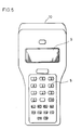
- FIG.5 shows a plan view of a bar code reader 10 using the above-mentioned CCD image sensor 3.
- FIG.6 shows a side view of the bar code reader 10 of FIG.5.
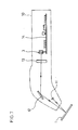
- FIG.7 shows a schematic illustration of main components in the bar code reader 10.
- FIG.8 shows a block diagram of the bar code reader 10.
- the bar code reader 10 has a key board 8 as keyed setting member having plural function keys (22 pieces in this embodiment), and a display 9 for indicating information.
- the function keys are used for inputting various information, for example, selecting operation from menus indicated by the display 9.
- the display 9, which comprises LCD (liquid-crystal display), is used for confirmation of the information inputted by function keys, confirmation of the information of the bar code symbol 1, and indication of the menus for operations.
- the display 9 is constructed to indicate such information by 112 dots X 32 dots.
- the bar code reader 10 comprises a LED (light emitting diode) light emitter 11 having plural LEDs in a line, reflection mirror 12, a lens 13 for creating a picture, an operation circuit 14 and the CCD image sensor 3 which comprises the image sensor 3a having 2048 pixels.
- the CCD image sensor 3 is reading the bar code symbol 1, the light reflected from the bar code symbol 1 is reflected on the reflection mirror 12 and passes through the lens 13 to the CCD image sensor 3.
- FIG.8 is a block diagram of the bar code reader 10.
- the above-mentioned operation circuit 14 of the bar code reader 10 comprises a microcomputer 15, a communication driver 22 for transmitting with a wire communication, a spread spectrum RF module 23 for transmitting with a wireless communication and a battery circuit 24.
- the microcomputer 15 has a counter 16 for counting bars of the bar code symbol 1, I/O port 17, serial port 18, CPU 19, ROM 20 and RAM 21.
- the microcomputer 15 is operated to follow a program stored in the ROM 20.
- the information of the bar code symbol 1 deciphered by the microcomputer 15 are produced from the serial port 18, and transmitted to an external terminal unit of the POS system via the communication driver 22 for a wire communication, or the spread spectrum RF module 23 for a wireless communication.
- information about the bar code symbol 1 is connected to an alarm 25, such as a buzzer or a lamp through the I/O port 17. Therefore, the bar code reader 10 can inform the information, such as a finish of the reading operation, by using the alarm 25. And further, the light of the LED light emitter 11, and the operation of the CCD image sensor 3 are controlled by the microcomputer 15 through the I/O port 17.
- the image sensor 3a is of a linear type having 2048 as number of pixels, and the digitizer circuit 3b is operated within a range between 4.5 volts and 5.5 volts.
- the communication driver 22 is used for a serial communication through a transmission cable, such as RS 232 C.
- the spread spectrum RF module 23 and the battery circuit 24 are used instead of the communication driver 22.
- the spread spectrum RF module 23 communicates the information of the bar code symbol 1 to an external terminal unit of the POS system through the serial port 18. And, setting operation for the bar code reader 10 can be performed from the external terminal by using the spread spectrum RF module 23.
- the spread spectrum RF module 23 is operated in the following specifications: the frequency band is set at a frequency from 902 MHz to 928 MHz, the output power is 100mW and the transmission rate is 242 KBPS (kilo-bit per second).
- the bar code reader 10 can communicate by using both of the wire communication and the wireless communication.
- a general radio transmission in a small power communication system is apt to be influenced by noise, and communicates at a low transmission rate, for example, 480 --- 2400 BPS (bit per second).
- the bar code reader 10 in accordance with the present invention can communicate in the high reliability and at high speed communications (242 KBPS) because the bar code reader 10 can use the spread spectrum RF module 23.
- the battery circuit 24 is used to feed power source for the bar code reader 10 in case of the wireless transmission.
- the bar code reader 10 has a charging terminal for charging electric power to the battery circuit 24 from an external power source.
- the CCD image sensor 3 having 14 x 200 /1.m per one pixel size is generally operated at an operation voltage from 4.5 volts to 5.5 volts d.c.
- the bar code reader in accordance with the present invention can use a CCD image sensor having a maximum voltage rating of 6 volts or less, such as about 3 volts d.c. supply.
- all circuits and units, such as a microcomputer etc., of the bar code reader are constituted to be operated at 3 volts. In this case, the bar code reader is very useful as a battery operation.
- a modified embodiment may be such that an image sensor is an area image sensor (plane type) having 512 x 492 pixels.
- the digitizer circuit 3b is provided as a digitizer. But apart therefrom, a modified embodiment may be such that the digitizer further comprises circuits which control filter factors, an amplification degree and an offset value, and which is integrally formed in the CCD image sensor. In this case, the bar code reader becomes the higher precision apparatus than the aforementioned embodiment.
- the filter factors, the amplification degree and the offset value may be controlled by an external unit of the POS system.
- the bar code reader can be configured in small size, for example, 25% less in size than the conventional one from our experience. And, the bar code reader having the CCD image sensor including the digitizer circuit is produced with low cost, for example, 10% down in cost than the conventional one.
- the bar code reader in accordance with the present invention can communicate by using of a spread spectrum RF module 23 as a radio transmission device, the high speed communication is reliably realized, and the bar code reader is useful in a noisy area, such as in a factory etc. In such area, the bar code reader in accordance with the present invention can be used to gather various data by using the bar code system.
- the bar code reader in accordance with the present invention can be configured in portably type, and can input and acquire data on real time.
Landscapes
- Physics & Mathematics (AREA)
- Electromagnetism (AREA)
- Engineering & Computer Science (AREA)
- Health & Medical Sciences (AREA)
- General Health & Medical Sciences (AREA)
- Toxicology (AREA)
- Artificial Intelligence (AREA)
- Computer Vision & Pattern Recognition (AREA)
- General Physics & Mathematics (AREA)
- Theoretical Computer Science (AREA)
- Image Input (AREA)
Applications Claiming Priority (2)
| Application Number | Priority Date | Filing Date | Title |
|---|---|---|---|
| JP5007299A JPH06215165A (ja) | 1993-01-20 | 1993-01-20 | デジタル出力イメージセンサおよびそれを用いたバーコードリーダ |
| JP7299/93 | 1993-01-20 |
Publications (3)
| Publication Number | Publication Date |
|---|---|
| EP0607965A2 true EP0607965A2 (de) | 1994-07-27 |
| EP0607965A3 EP0607965A3 (de) | 1994-12-21 |
| EP0607965B1 EP0607965B1 (de) | 1999-04-14 |
Family
ID=11662153
Family Applications (1)
| Application Number | Title | Priority Date | Filing Date |
|---|---|---|---|
| EP94100794A Expired - Lifetime EP0607965B1 (de) | 1993-01-20 | 1994-01-20 | Balkenkodierleser ausgestattet mit einem digitalen Ausgabe-Bildsensor |
Country Status (3)
| Country | Link |
|---|---|
| EP (1) | EP0607965B1 (de) |
| JP (1) | JPH06215165A (de) |
| DE (1) | DE69417779T2 (de) |
Family Cites Families (3)
| Publication number | Priority date | Publication date | Assignee | Title |
|---|---|---|---|---|
| EP0048805B1 (de) * | 1980-09-29 | 1985-05-22 | International Business Machines Corporation | Integrierte opto-elektrische Halbleiter-Bildwandler-Schaltung |
| ES2039493T3 (es) * | 1987-04-22 | 1993-10-01 | Abbott Laboratories | Lectores y formatos de codigo optico. |
| JPH0448392A (ja) * | 1990-06-18 | 1992-02-18 | Fujitsu Ltd | バーコード読み取り装置 |
-
1993
- 1993-01-20 JP JP5007299A patent/JPH06215165A/ja active Pending
-
1994
- 1994-01-20 EP EP94100794A patent/EP0607965B1/de not_active Expired - Lifetime
- 1994-01-20 DE DE69417779T patent/DE69417779T2/de not_active Expired - Fee Related
Also Published As
| Publication number | Publication date |
|---|---|
| EP0607965A3 (de) | 1994-12-21 |
| DE69417779D1 (de) | 1999-05-20 |
| DE69417779T2 (de) | 1999-08-12 |
| EP0607965B1 (de) | 1999-04-14 |
| JPH06215165A (ja) | 1994-08-05 |
Similar Documents
| Publication | Publication Date | Title |
|---|---|---|
| US5532469A (en) | Hand held bar code reader with input and display device and processor | |
| US5065003A (en) | Portable data input/transmission apparatus | |
| US5850189A (en) | Apparatus and method for infrared communication | |
| US5256865A (en) | Automatic sensing and programming circuit and programming method for optical scanners | |
| US4879540A (en) | Data exchanging system using a bar code reader | |
| EP1052609B1 (de) | Fernbedienungssystem mit rekonfigurierbare Fernsteuereinrichtung | |
| US5654533A (en) | Apparatus and method for reading two-dimensional symbols | |
| AU7647591A (en) | Two and three wire utility data communications system | |
| GB2163324A (en) | Transponder | |
| AU2001288990A1 (en) | Method and device for signaling data transfer between a usb port and a usb smart card module | |
| US5237163A (en) | Method for scanning a plurality of bar code labels | |
| US5214268A (en) | Apparatus for programming a bar code reader | |
| US6978934B2 (en) | Method and apparatus for reducing data collection device power consumption | |
| EP0607965A2 (de) | Digitaler Ausgabe-Bildsensor und ein mit diesem ausgestatteter Balkenkodierleser | |
| US5629511A (en) | Bar code scanner and scanning system for various types of operations | |
| CN101887515A (zh) | 图像及条码识读模组及其应用装置 | |
| ATE182679T1 (de) | Positionsmesssystem | |
| US5764099A (en) | Integrated voltage regulating circuit useful in high voltage electronic encoders | |
| US5940199A (en) | Interface unit and information processing apparatus having the interface unit | |
| CA2213395A1 (en) | Computer wireless receiver | |
| EP0524653B1 (de) | Strichkodeleser | |
| GB2183070A (en) | Bar-code reader | |
| CN210924898U (zh) | 一种适配广自学习的多功能遥控器 | |
| KR100262135B1 (ko) | 컴퓨터 무선 수신 장치 | |
| KR100193270B1 (ko) | 렌즈 정보 인식 장치 |
Legal Events
| Date | Code | Title | Description |
|---|---|---|---|
| PUAI | Public reference made under article 153(3) epc to a published international application that has entered the european phase |
Free format text: ORIGINAL CODE: 0009012 |
|
| AK | Designated contracting states |
Kind code of ref document: A2 Designated state(s): DE FR GB IT |
|
| PUAL | Search report despatched |
Free format text: ORIGINAL CODE: 0009013 |
|
| AK | Designated contracting states |
Kind code of ref document: A3 Designated state(s): DE FR GB IT |
|
| 17P | Request for examination filed |
Effective date: 19950321 |
|
| 17Q | First examination report despatched |
Effective date: 19970710 |
|
| GRAG | Despatch of communication of intention to grant |
Free format text: ORIGINAL CODE: EPIDOS AGRA |
|
| GRAG | Despatch of communication of intention to grant |
Free format text: ORIGINAL CODE: EPIDOS AGRA |
|
| GRAH | Despatch of communication of intention to grant a patent |
Free format text: ORIGINAL CODE: EPIDOS IGRA |
|
| GRAH | Despatch of communication of intention to grant a patent |
Free format text: ORIGINAL CODE: EPIDOS IGRA |
|
| GRAA | (expected) grant |
Free format text: ORIGINAL CODE: 0009210 |
|
| AK | Designated contracting states |
Kind code of ref document: B1 Designated state(s): DE FR GB IT |
|
| ITF | It: translation for a ep patent filed | ||
| REF | Corresponds to: |
Ref document number: 69417779 Country of ref document: DE Date of ref document: 19990520 |
|
| ET | Fr: translation filed | ||
| PLBE | No opposition filed within time limit |
Free format text: ORIGINAL CODE: 0009261 |
|
| STAA | Information on the status of an ep patent application or granted ep patent |
Free format text: STATUS: NO OPPOSITION FILED WITHIN TIME LIMIT |
|
| 26N | No opposition filed | ||
| REG | Reference to a national code |
Ref country code: GB Ref legal event code: IF02 |
|
| PGFP | Annual fee paid to national office [announced via postgrant information from national office to epo] |
Ref country code: GB Payment date: 20070117 Year of fee payment: 14 |
|
| PGFP | Annual fee paid to national office [announced via postgrant information from national office to epo] |
Ref country code: DE Payment date: 20070118 Year of fee payment: 14 |
|
| PGFP | Annual fee paid to national office [announced via postgrant information from national office to epo] |
Ref country code: IT Payment date: 20070601 Year of fee payment: 14 |
|
| PGFP | Annual fee paid to national office [announced via postgrant information from national office to epo] |
Ref country code: FR Payment date: 20070109 Year of fee payment: 14 |
|
| GBPC | Gb: european patent ceased through non-payment of renewal fee |
Effective date: 20080120 |
|
| PG25 | Lapsed in a contracting state [announced via postgrant information from national office to epo] |
Ref country code: DE Free format text: LAPSE BECAUSE OF NON-PAYMENT OF DUE FEES Effective date: 20080801 |
|
| REG | Reference to a national code |
Ref country code: FR Ref legal event code: ST Effective date: 20081029 |
|
| PG25 | Lapsed in a contracting state [announced via postgrant information from national office to epo] |
Ref country code: GB Free format text: LAPSE BECAUSE OF NON-PAYMENT OF DUE FEES Effective date: 20080120 |
|
| PG25 | Lapsed in a contracting state [announced via postgrant information from national office to epo] |
Ref country code: FR Free format text: LAPSE BECAUSE OF NON-PAYMENT OF DUE FEES Effective date: 20080131 |
|
| PG25 | Lapsed in a contracting state [announced via postgrant information from national office to epo] |
Ref country code: IT Free format text: LAPSE BECAUSE OF NON-PAYMENT OF DUE FEES Effective date: 20080120 |