EP0608026A2 - Connecteur multiple pour rubans de fibres optiques - Google Patents
Connecteur multiple pour rubans de fibres optiques Download PDFInfo
- Publication number
- EP0608026A2 EP0608026A2 EP94200095A EP94200095A EP0608026A2 EP 0608026 A2 EP0608026 A2 EP 0608026A2 EP 94200095 A EP94200095 A EP 94200095A EP 94200095 A EP94200095 A EP 94200095A EP 0608026 A2 EP0608026 A2 EP 0608026A2
- Authority
- EP
- European Patent Office
- Prior art keywords
- multiple connector
- fibre optic
- optic ribbons
- fibre
- ribbon
- Prior art date
- Legal status (The legal status is an assumption and is not a legal conclusion. Google has not performed a legal analysis and makes no representation as to the accuracy of the status listed.)
- Withdrawn
Links
- 239000000835 fiber Substances 0.000 title claims abstract description 30
- 238000010168 coupling process Methods 0.000 claims abstract description 18
- 238000005859 coupling reaction Methods 0.000 claims abstract description 18
- 230000008878 coupling Effects 0.000 claims abstract description 15
- 230000003287 optical effect Effects 0.000 claims abstract description 9
- 238000000034 method Methods 0.000 claims description 6
- 229920000271 Kevlar® Polymers 0.000 claims description 3
- 238000007667 floating Methods 0.000 claims description 3
- 239000004761 kevlar Substances 0.000 claims description 3
- 238000000465 moulding Methods 0.000 claims description 3
- 239000004033 plastic Substances 0.000 claims description 3
- 229920003023 plastic Polymers 0.000 claims description 3
- 239000011248 coating agent Substances 0.000 claims description 2
- 238000000576 coating method Methods 0.000 claims description 2
- 238000002788 crimping Methods 0.000 claims description 2
- 239000000463 material Substances 0.000 claims description 2
- 239000011347 resin Substances 0.000 claims description 2
- 229920005989 resin Polymers 0.000 claims description 2
- 238000002360 preparation method Methods 0.000 claims 1
- 239000000853 adhesive Substances 0.000 description 2
- 230000001070 adhesive effect Effects 0.000 description 2
- 238000002604 ultrasonography Methods 0.000 description 2
- 230000000712 assembly Effects 0.000 description 1
- 238000000429 assembly Methods 0.000 description 1
- 230000005540 biological transmission Effects 0.000 description 1
- 239000000470 constituent Substances 0.000 description 1
- 238000010276 construction Methods 0.000 description 1
- 230000014759 maintenance of location Effects 0.000 description 1
- 239000002991 molded plastic Substances 0.000 description 1
Images

Classifications
-
- G—PHYSICS
- G02—OPTICS
- G02B—OPTICAL ELEMENTS, SYSTEMS OR APPARATUS
- G02B6/00—Light guides; Structural details of arrangements comprising light guides and other optical elements, e.g. couplings
- G02B6/24—Coupling light guides
- G02B6/36—Mechanical coupling means
- G02B6/38—Mechanical coupling means having fibre to fibre mating means
- G02B6/3807—Dismountable connectors, i.e. comprising plugs
- G02B6/3873—Connectors using guide surfaces for aligning ferrule ends, e.g. tubes, sleeves, V-grooves, rods, pins, balls
- G02B6/3874—Connectors using guide surfaces for aligning ferrule ends, e.g. tubes, sleeves, V-grooves, rods, pins, balls using tubes, sleeves to align ferrules
- G02B6/3878—Connectors using guide surfaces for aligning ferrule ends, e.g. tubes, sleeves, V-grooves, rods, pins, balls using tubes, sleeves to align ferrules comprising a plurality of ferrules, branching and break-out means
Definitions
- This invention relates to a multiple connector for multi-fibre optic ribbons.
- a ribbon containing at least two optical fibres is inserted into each of them.
- Afitting projection is provided at the end distant from that through which the ribbon is inserted, at the same end there also being provided two centering or guide elements.
- Said centering elements are in the form of a pin element and a hole, each located on one side of the fitting projection, to be inserted into the hole or to receive the pin element of the other connector respectively.
- the two plugs are positioned facing each other. More specifically, two fitting projections internally containing individual fibres of the multi-fibre ribbon are coupled together.
- the centering elements In addition to centering the two fitting projections, the centering elements also lock the pair of plugs. In this respect, the connection is achieved by respectively inserting the two pin elements into the two holes of each of said facing plugs.
- a further drawback is the need to align individual fibres. As the fibre core diameter is just a few microns it is very difficult to simultaneously align two or more fibres to ensure a good connection.
- An object of the present invention is to provide a multiple connector which achieves multiple connection of optical fibres whi le using a space less than that currently necessary.
- a further object is to achieve a multiple connection by means of several independent connections, made as separate connections.
- a further object is to facilitate the mounting of the connector by eliminating bonding by adhesive or ultrasound.
- a further object of the invention is to ensure correct operation and good positioning of the movable parts during coupling, uncoupling and operation.
- a further object is to provide a valid locking element which prevents any accidental uncoupling of said connectors due to pulling on the cable.
- a multiple connector for multi-fibre optic ribbons comprising two facing plugs snap-insertable into a coupling consisting of a plurality of bushes locked together by a locking device, each of said plugs comprising a butting chamber and a plurality of ferrules each complete with a support socket and a helical spring, said butting chamber having a cover and containing a plurality of individual optical fibres.
- Figures 1 and 2 show a multiple connector for multi-fibre optic ribbons according to the present invention, indicated overall by the reference numeral 10.
- the connector 10 consists of two facing plugs 11 snap-inserted into a coupling 12. This latter interposed between the plugs 11 acts as a locking element and also as the element which connects them together.
- a butting chamber 13 with a snap-cover 14 At that end of the plug 11 distant from the end to be inserted into the coupling 12 there is a butting chamber 13 with a snap-cover 14.
- the chamber 13 is connected to a protection shell 15 of rubber or another similar material, through the interior of which a cable or ribbon 16 also comprising outer protection is inserted.
- the ribbon 16 is a multi-fibre ribbon containing at least two optical fibres, and in particular four in a preferred embodiment.
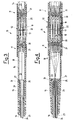
- Figures 3 and 4 show in detail the manner in which the connector 10 is butt-coupled to the ribbon 16.
- the plastics components of the connector 10 are formed by moulding, and to facilitate subsequent assembly are provided with elastic projections.
- the coupling 12 and plugs 11 are preassembled.
- Preassembly of the coupling 12 consists of inserting four bushes 17 into the coupling 12, ie into its shell. When said bushes 17 have been inserted they are locked by a locking device 18 which is inserted as an interference fit.
- the locking device 18 is designed and inserted into the shell of the coupling 12 such that the bushes 17 are locked but remain floating.
- Preassembly of the plugs 11 consists of inserting four ferrules 19 each complete with a support socket 20 and a helical spring 21 into the body 31 of the plug 11.
- the butt-coupling of the ribbon 16 is commenced by preparing the so-called cord head, ie that portion of said ribbon 16 to be used for the connection.
- the outer sheathing 23 of said portion of the ribbon 16 is stripped off. This exposes a layer of kevlar strands 24, the ribbon 16 then being inserted through the protection shell 15 and into the butting chamber 13.
- this latter is mounted on a knurled support 25 on said chamber 13.
- a recess 26 is provided in an outer surface of the knurled support 25 to act as a seat for a projecting inner edge 27 of the protection shell 15. Having mounted the shell 15 to face the butting chamber 13, the projecting inner edge 27 is inserted into the recess 26.
- the coupling 12 interposed between the two plugs 11 is formed in such a manner as to ensure both good contact between respective fibres 30 of the two facing plugs 11 and permanent coupling between them. Retention between the parts is provided by a push-pull connection which enables the multiple connector to be coupled and uncoupled by applying a simple axial force.
- One of the advantages of the multiple connector for multi-fibre optic ribbons is its geometrically planar structure.
- the arrangement of the four ferrules is rectilinear and individually retractable to form four independent connections, with the possibility of floating each of them.
- Afurther advantage is a completely open fibre introduction chamber which is inspectionable at any moment.
- a further advantage is the plastics construction of the connector parts.
- the moulding process enables the holes within which the ferrules with their respective support sockets and the bushes slide to be made perfectly smooth and free of impressions and mould closure signs.
- various elastic fitting projections enables bonding by adhesive or ultrasound to be completely eliminated, with the advantage of simpler and more reliable mechanical connections.
- An important advantage is the method for fixing the ferrules to the plug body by a moulded plastics device incorporating reopenable snap-fitting.
- the assemblies can if necessary be reopened using a simple tool, so enabling the ferrules or bushes to be recovered.
- Afurther advantage is the coupling release push-pull device formed in such a manner as not to increase the overall size of the connector.
- such a coupling eliminates accidental release of the plugs resulting from a simple pull on one or both ribbons.
- a further important advantage is the small dimensions of the multiple connector according to the present invention compared with conventional connectors.
Landscapes
- Physics & Mathematics (AREA)
- General Physics & Mathematics (AREA)
- Optics & Photonics (AREA)
- Mechanical Coupling Of Light Guides (AREA)
Applications Claiming Priority (2)
| Application Number | Priority Date | Filing Date | Title |
|---|---|---|---|
| ITMI930088 | 1993-01-21 | ||
| ITMI930088A IT1263785B (it) | 1993-01-21 | 1993-01-21 | Connettore multiplo per nastri multi-fibre ottiche |
Publications (2)
| Publication Number | Publication Date |
|---|---|
| EP0608026A2 true EP0608026A2 (fr) | 1994-07-27 |
| EP0608026A3 EP0608026A3 (fr) | 1995-01-18 |
Family
ID=11364711
Family Applications (1)
| Application Number | Title | Priority Date | Filing Date |
|---|---|---|---|
| EP94200095A Withdrawn EP0608026A3 (fr) | 1993-01-21 | 1994-01-15 | Connecteur multiple pour rubans de fibres optiques. |
Country Status (3)
| Country | Link |
|---|---|
| US (1) | US5436993A (fr) |
| EP (1) | EP0608026A3 (fr) |
| IT (1) | IT1263785B (fr) |
Cited By (2)
| Publication number | Priority date | Publication date | Assignee | Title |
|---|---|---|---|---|
| ES2343614A1 (es) * | 2008-10-15 | 2010-08-04 | Nordix, S.A. | Derivador compacto de exterior para transicion horizontal / vertical de cable de fibra optica. |
| CN106918869A (zh) * | 2017-04-17 | 2017-07-04 | 深圳市飞博康光通讯技术有限公司 | 一种lc双联连接器 |
Families Citing this family (5)
| Publication number | Priority date | Publication date | Assignee | Title |
|---|---|---|---|---|
| US5521998A (en) * | 1994-12-13 | 1996-05-28 | United Technologies Corporation | Strain relief backshell for fiber optic transmission lines |
| CN1187632C (zh) | 2000-02-11 | 2005-02-02 | 胡贝尔和茹纳股份公司 | 用于光插塞连接器的接头和具有这种接头的光插塞连接器 |
| US6485189B1 (en) * | 2001-05-09 | 2002-11-26 | Stratos Lightwave, Inc. | High density multiple fiber optic connector |
| EP1649312A1 (fr) * | 2003-07-31 | 2006-04-26 | Huber + Suhner Ag | Procede de liaison amovible de deux groupes de fibres optiques, et connecteur a broches pour la mise en oeuvre de ce procede |
| US8403570B2 (en) * | 2008-04-10 | 2013-03-26 | Amphenol Corporation | Plural fiber optic interconnect |
Citations (1)
| Publication number | Priority date | Publication date | Assignee | Title |
|---|---|---|---|---|
| EP0414438A2 (fr) * | 1989-08-21 | 1991-02-27 | The Whitaker Corporation | Moyens pour assembler des éléments de codage avec un connecteur |
Family Cites Families (14)
| Publication number | Priority date | Publication date | Assignee | Title |
|---|---|---|---|---|
| US4291943A (en) * | 1977-08-05 | 1981-09-29 | Minnesota Mining And Manufacturing Company | Connector for optical fiber cables |
| FR2443075A1 (fr) * | 1978-08-29 | 1980-06-27 | Comp Generale Electricite | Fiche de connecteur fibre a fibre avec element de raccordement a un cable optique |
| US4645295A (en) * | 1980-02-04 | 1987-02-24 | Allied Corporation | Fiber optic connector |
| JPS59141308U (ja) * | 1983-03-10 | 1984-09-21 | 第一電子工業株式会社 | 多芯光フアイバケ−ブル用コネクタ |
| US4712864A (en) * | 1985-05-02 | 1987-12-15 | Luxtron Corporation | Multi-channel fiber optic connector |
| JPH077139B2 (ja) * | 1985-12-24 | 1995-01-30 | 日本電信電話株式会社 | 浮動ホルダ型光コネクタ |
| US4789218A (en) * | 1987-03-30 | 1988-12-06 | Methode Electronics, Inc. | Spring-biased fiber optic contact |
| US5018822A (en) * | 1989-12-11 | 1991-05-28 | Litton Systems, Inc. | Environmentally sealed multichannel fiber optic connector |
| US5199093A (en) * | 1990-05-22 | 1993-03-30 | Bicc Plc. | Multi-part optical fibre connectors |
| US5133032A (en) * | 1991-04-17 | 1992-07-21 | Salter James R | Optical fiber connector |
| ES2089319T3 (es) * | 1991-09-04 | 1996-10-01 | Furukawa Electric Co Ltd | Conector optico de nucleos multiples. |
| US5325454A (en) * | 1992-11-13 | 1994-06-28 | International Business Machines, Corporation | Fiber optic connector housing |
| US5295214A (en) * | 1992-11-16 | 1994-03-15 | International Business Machines Corporation | Optical module with tolerant wave soldered joints |
| US5333225A (en) * | 1993-08-03 | 1994-07-26 | International Business Machines Corporation | Substrate-embedded pluggable receptacles for connecting clustered optical cables to a module |
-
1993
- 1993-01-21 IT ITMI930088A patent/IT1263785B/it active IP Right Grant
-
1994
- 1994-01-15 EP EP94200095A patent/EP0608026A3/fr not_active Withdrawn
- 1994-01-18 US US08/184,879 patent/US5436993A/en not_active Expired - Fee Related
Patent Citations (1)
| Publication number | Priority date | Publication date | Assignee | Title |
|---|---|---|---|---|
| EP0414438A2 (fr) * | 1989-08-21 | 1991-02-27 | The Whitaker Corporation | Moyens pour assembler des éléments de codage avec un connecteur |
Cited By (5)
| Publication number | Priority date | Publication date | Assignee | Title |
|---|---|---|---|---|
| ES2343614A1 (es) * | 2008-10-15 | 2010-08-04 | Nordix, S.A. | Derivador compacto de exterior para transicion horizontal / vertical de cable de fibra optica. |
| ES2343614B1 (es) * | 2008-10-15 | 2011-10-03 | Nordix, S.A. | Derivador compacto de exterior para transicion horizontal / vertical de cable de fibra optica. |
| CN106918869A (zh) * | 2017-04-17 | 2017-07-04 | 深圳市飞博康光通讯技术有限公司 | 一种lc双联连接器 |
| WO2018192079A1 (fr) * | 2017-04-17 | 2018-10-25 | 深圳市飞博康光通讯技术有限公司 | Connecteur lc duplex |
| CN106918869B (zh) * | 2017-04-17 | 2018-10-26 | 深圳市飞博康光通讯技术有限公司 | 一种lc双联连接器 |
Also Published As
| Publication number | Publication date |
|---|---|
| US5436993A (en) | 1995-07-25 |
| ITMI930088A0 (it) | 1993-01-21 |
| IT1263785B (it) | 1996-08-29 |
| ITMI930088A1 (it) | 1994-07-21 |
| EP0608026A3 (fr) | 1995-01-18 |
Similar Documents
| Publication | Publication Date | Title |
|---|---|---|
| US11892689B2 (en) | Optical fiber connection system including optical fiber alignment device | |
| US4515434A (en) | Fiber optic connector | |
| US10371899B2 (en) | Fiber optic connector | |
| US5276752A (en) | Fiber optic connector system | |
| US4105285A (en) | Single optical fiber connector | |
| US5452386A (en) | Fiber optics connector and a method of making the same | |
| US20160085037A1 (en) | Methods for forming connectorized fiber optic cabling | |
| CA2245838A1 (fr) | Connecteur de fibres optiques et manchon de connecteur | |
| US5892871A (en) | Fiber optic cable termination | |
| GB1563077A (en) | Connector for light conductive cables | |
| EP4577861A1 (fr) | Ferrule multifibre à transition conique en perçage de ferrule | |
| EP4272026B1 (fr) | Connecteur mpo pouvant être poussé | |
| US5436993A (en) | Multiple connector for multi-fibre optic ribbons | |
| WO1994000785A2 (fr) | Manchon terminal de guide d'ondes optique | |
| US6234681B1 (en) | Apparatus and method for interconnecting optical fibers | |
| US4306766A (en) | Optical fiber terminals with V-groove alignment | |
| EP1193516A2 (fr) | Adaptateur de couplage pour usage avec connecteurs à fibres optiques | |
| EP0574462B1 (fr) | Raccord pour fibre optique et son procede de production | |
| EP0024959A1 (fr) | Connecteur pour guides d'ondes optiques | |
| AU755885B2 (en) | Massive parallel optical interconnect system | |
| JP2913549B1 (ja) | 多心光コネクタ | |
| WO2003076973A2 (fr) | Adaptateur monobloc |
Legal Events
| Date | Code | Title | Description |
|---|---|---|---|
| PUAI | Public reference made under article 153(3) epc to a published international application that has entered the european phase |
Free format text: ORIGINAL CODE: 0009012 |
|
| AK | Designated contracting states |
Kind code of ref document: A2 Designated state(s): DE ES FR GB PT SE |
|
| PUAL | Search report despatched |
Free format text: ORIGINAL CODE: 0009013 |
|
| AK | Designated contracting states |
Kind code of ref document: A3 Designated state(s): DE ES FR GB PT SE |
|
| 17P | Request for examination filed |
Effective date: 19950329 |
|
| 17Q | First examination report despatched |
Effective date: 19961122 |
|
| STAA | Information on the status of an ep patent application or granted ep patent |
Free format text: STATUS: THE APPLICATION IS DEEMED TO BE WITHDRAWN |
|
| 18D | Application deemed to be withdrawn |
Effective date: 20000801 |