EP0608035B1 - Light-shielding device for a screen - Google Patents
Light-shielding device for a screen Download PDFInfo
- Publication number
- EP0608035B1 EP0608035B1 EP94200132A EP94200132A EP0608035B1 EP 0608035 B1 EP0608035 B1 EP 0608035B1 EP 94200132 A EP94200132 A EP 94200132A EP 94200132 A EP94200132 A EP 94200132A EP 0608035 B1 EP0608035 B1 EP 0608035B1
- Authority
- EP
- European Patent Office
- Prior art keywords
- strips
- screen
- shielding device
- strip
- light
- Prior art date
- Legal status (The legal status is an assumption and is not a legal conclusion. Google has not performed a legal analysis and makes no representation as to the accuracy of the status listed.)
- Expired - Lifetime
Links
- 239000000463 material Substances 0.000 claims description 8
- 230000003247 decreasing effect Effects 0.000 abstract 1
- 230000004048 modification Effects 0.000 description 5
- 238000012986 modification Methods 0.000 description 5
- 230000007423 decrease Effects 0.000 description 2
- 239000007787 solid Substances 0.000 description 2
- 230000001154 acute effect Effects 0.000 description 1
- 230000002411 adverse Effects 0.000 description 1
- 238000005452 bending Methods 0.000 description 1
- 230000000694 effects Effects 0.000 description 1
- 239000011521 glass Substances 0.000 description 1
- 238000001746 injection moulding Methods 0.000 description 1
- 238000009877 rendering Methods 0.000 description 1
Images


Classifications
-
- H—ELECTRICITY
- H04—ELECTRIC COMMUNICATION TECHNIQUE
- H04N—PICTORIAL COMMUNICATION, e.g. TELEVISION
- H04N5/00—Details of television systems
- H04N5/64—Constructional details of receivers, e.g. cabinets or dust covers
- H04N5/65—Holding-devices for protective discs or for picture masks
-
- H—ELECTRICITY
- H01—ELECTRIC ELEMENTS
- H01J—ELECTRIC DISCHARGE TUBES OR DISCHARGE LAMPS
- H01J29/00—Details of cathode-ray tubes or of electron-beam tubes of the types covered by group H01J31/00
- H01J29/86—Vessels; Containers; Vacuum locks
- H01J29/89—Optical or photographic arrangements structurally combined or co-operating with the vessel
Definitions
- the present invention relates to collapsible light-shielding device for a display screen comprising a number of strips essentially enclosing one another in a tight manner, said strips being attachable to a display screen and being slidable over one another towards the screen to a pushed-in position in which the strips essentially cover one another and away from the screen to a pushed-out position, in which the strips are essentially uncovered.
- the strips of this device define substantially rectangular members with one side open.
- the strips are at their end parts provided with hook elements for interacting with hook elements on adjacent strips, one hook element being provided on the end part of the strip that is located towards the screen and facing the outer surface of an adjacent strip for clampingly engaging with the outer surface of the adjacent strip when placed in a position locted away from the screen, and a second hook element provided on the end part of the strip that is located away from the screen, the second hook element extending in a direction opposite to the first hook element.
- Another shielding device of this kind is disclosed in US-A-4,444,465 and consists of an undeformable U-shaped shaft section of flanged plastic plate material. Said shaft section is placed upside down over the housing of the screen, i.e. with the legs of the shaft section pointing downwards. Thus, the body of the shaft section rests on the upper side of said housing, while its legs are on either side of the screen. In the extended position, said shaft section projects from the housing beyond the displaying screen and prevents irritating reflections of natural light and/or artificial light on the glass of the screen, thereby rendering the image shown on the displaying screen clearer. Said known shielding device is collapsible by pushing it over the housing into a position in which the shielding device does not project beyond the screen.
- This known shielding device also has several disadvantages.
- a special fastening device is required which consists of a bracket which has to be attached on top of the housing.
- a relatively expensive part is required which greatly affects the outward appearance of the housing.
- the shielding device is bulky under any circumstance, which can be irritating and may also adversely affect the outward appearance of the housing of the screen.
- the user is required to sit straight in front of the displaying screen when the shielding device is extended, as the shielding device is too much of a nuisance when viewing the displaying screen at an angle.
- the object of the invention is to provide an improved extendable shielding device.
- the light-shielding device according to the invention is characterized in that the strips define a closed substantially rectangular member, comprising pairs of oppositely located strips the distance between the outer surfaces of a pair of strips being smaller for the end parts located towards the screen than for the end parts located away from the screen.
- the light-shielding device can easily be fitted to a screen, for example using Velcro.
- pairs of oppositely located strips of the light-shielding device have an increasing distance between the outer surfaces, viewed in axial direction, it is possible to place the light-shielding device in various positions relative to the face of the screen, so that the displaying screen can be viewed from different angles without hindrance.
- the invention provides an adapter member providing a flat attachment face for the light-shielding device.
- the adapter member provides a flat attachment face for the light-shielding device.
- the strips can be of solid design, for example produced by injection-moulding, but may also be produced by bending plate material, preferably provided with integrated hook or locking elements.
- the present invention provides a collapsible light-shielding device for a screen, which consists of as few parts as possible, is inexpensive to produce, operates reliably and can easily be fitted to a monitor.
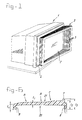
- Figure 1 shows a monitor 1 having a displaying screen 2 around which a light-shielding device 3 according to the present invention has been fitted.
- said light-shielding device 3 has a flange 4 by means of which it is attached to the monitor 1, as well as a number of, preferably 10, plate-shaped annular strips 5 which are concentrically nested with little play.
- the light-shielding device as shown in the drawing is extended less far at the front than at the back, thereby enabling the displaying screen 2 to be viewed at a relatively acute angle.
- Other positions of the light-shielding device can also be effected, for example a downward or upward angle, if desired in combination with a sideways angle.
- Figure 2 only shows the innermost strip 5' connected with the monitor 1 and two further strips 5 directly adjacent thereto.
- the strip 5' has a flange 4 protruding at right angles, and at the other end a hook 6.
- the further strips 5 have a hook 6 on the one end and a hook 7 at the other end, which hook 7 protrudes from the opposite side. It can clearly be seen that the hook 7 of the further strip 5 interacts with the hook 6 of the strip 5', thereby preventing the further strip 5 from being extended further over the strip 5' in the direction of the arrow A, and the light-shielding device 3 from separating into its component parts.
- each further strip 5, of which only two are shown here but of which there are usually nine, has a locking projection 8 at the end near the hook 7, on the side of the hook 6.
- a projection 8 of one further strip 5 interacts with the hook 7 of the other further strip 5, when these further strips 5 are pushed over one another counter to the direction of the arrow A. It is thereby ensured that the other further strips 5 are likewise pushed in, ultimately over the fixed strip 5', when the outermost further strip 5 is being pushed counter to the direction of the arrow A.
- Figure 2 shows how the flange 4 is connected to the monitor 1 with the interposition of an adapter member 9 likewise shown in cross section.
- Said adapter member 9 is essentially plate-shaped and runs in a concentrically annular manner around the displaying screen 2, as do the strip 5' and the further strips 5.
- the adapter member 9 On the side facing away from the flange 4, the adapter member 9 has a recess 10 which is filled with a felt-like or sponge-like material which can be compressed to a large extent. As can be seen, said recess 10 extends from the radial inner edge of the adapter member.
- the adapter member 9 On the radial outer edge, also on the side facing away from the flange 4, the adapter member 9 has an axial projection 11 which grips around the monitor 1.
- the projection 11 serves as a kind of apron by means of which the adapter member 9 can be attached to the monitor 1 in an attractive manner, without too large a gap being formed.
- a convex shape of the front of the monitor can be compensated for by the space 10, which is filled with highly compressible material and by means of which the adapter member 9 provides a flat attachment face for the flange 4.
- the recess 10 may, for example, not be present on any of the four corners of the adapter member, so that there the adapter member 9 bears against the monitor 1 with its entire surface.
- Figure 3 shows part of the light-shielding device of Figures 1 and 2 in a different extended position. It can clearly be seen how the hooks 6 and 7 on the strips 5 and 5' interact. In this case as well, only the fixed strip 5' and the next three further strips 5 have been shown for the sake of clarity.
- Figure 4 shows the profile section of the strips 5.
- the total length is 16 mm.
- the thickness t1 is 1.1 mm; on the side of the hook 7, the thickness t 2 is 0.6 mm.
- the total height of the profile section on the side of the hook 6 is 2.1 mm; on the side of the hook 7, the total height is 3.1 mm.
- the thickness of every strip 5, 5' decreases in the axial direction, the thickness on the side of the hook 6 being greater than that on the side of the hook 7.
- Figure 5 shows a modification of the profile section shown in Figure 4.
- the modification shown in Figure 5 is a bent profile section made from plate material with integrated hooks 6 and 7 and projection 8.
- the decrease in thickness can be effected in a way similar to that of the embodiment of Figure 4.
- Figure 6 shows another modification to the profile section of the strips 5.
- the total length is 21,25 mm.
- the thickness t 1 is 1.1 mm; on the side of the hook 7, the thickness t 2 is 1.9 mm.
- the total height of the profile section on the side of the hook 6 (t 4 ) is 1.9 mm; on the side of the hook 7 (t 3 ), the total height is 4.1 mm.
- the thickness of the strip is constant.
- the lower face 20 is substantially flat; merely the outer part at hook 6 is somewhat lowered.
- the upper face 21 is inclined. The greatest inclination is indicated at arrow C. However, at arow A, the inclination still is 2°, while at arrow B the inclination is 5°30'.
- the strip according to fig. 6 provides improved positioning of the strips with respect to each other since the provision of the part at constant thickness.
Landscapes
- Engineering & Computer Science (AREA)
- Multimedia (AREA)
- Signal Processing (AREA)
- Non-Portable Lighting Devices Or Systems Thereof (AREA)
- Fittings On The Vehicle Exterior For Carrying Loads, And Devices For Holding Or Mounting Articles (AREA)
- Push-Button Switches (AREA)
- Devices For Indicating Variable Information By Combining Individual Elements (AREA)
- Curtains And Furnishings For Windows Or Doors (AREA)
- Eye Examination Apparatus (AREA)
- Details Of Aerials (AREA)
- Chair Legs, Seat Parts, And Backrests (AREA)
- Studio Devices (AREA)
Applications Claiming Priority (2)
| Application Number | Priority Date | Filing Date | Title |
|---|---|---|---|
| NL9300110A NL9300110A (nl) | 1993-01-20 | 1993-01-20 | Lichtscherm voor een beeldscherm. |
| NL9300110 | 1993-01-20 |
Publications (2)
| Publication Number | Publication Date |
|---|---|
| EP0608035A1 EP0608035A1 (en) | 1994-07-27 |
| EP0608035B1 true EP0608035B1 (en) | 1998-07-22 |
Family
ID=19861947
Family Applications (1)
| Application Number | Title | Priority Date | Filing Date |
|---|---|---|---|
| EP94200132A Expired - Lifetime EP0608035B1 (en) | 1993-01-20 | 1994-01-20 | Light-shielding device for a screen |
Country Status (8)
| Country | Link |
|---|---|
| US (1) | US5418642A (da) |
| EP (1) | EP0608035B1 (da) |
| AT (1) | ATE168818T1 (da) |
| DE (1) | DE69411763T2 (da) |
| DK (1) | DK0608035T3 (da) |
| ES (1) | ES2121596T3 (da) |
| GR (1) | GR3027734T3 (da) |
| NL (1) | NL9300110A (da) |
Families Citing this family (11)
| Publication number | Priority date | Publication date | Assignee | Title |
|---|---|---|---|---|
| CN1062405C (zh) * | 1996-09-19 | 2001-02-21 | 周石生 | 显象管荧光屏防辐射装置 |
| AU8268098A (en) * | 1997-06-26 | 1999-01-19 | Via, Inc. | Inflatable optical housing |
| GB9900246D0 (en) * | 1999-01-08 | 1999-02-24 | Savage Peter | Screen surrond |
| GB2359231A (en) * | 2000-02-14 | 2001-08-15 | Hazel Hassan | Sunshade for a computer |
| US6775038B2 (en) * | 2000-11-30 | 2004-08-10 | Paul R. Edwards | Image maintenance shield |
| US6519086B2 (en) | 2000-11-30 | 2003-02-11 | Paul R. Edwards | Image maintenance shield |
| US7083291B1 (en) * | 2002-10-24 | 2006-08-01 | Peter Yong | Glare shield for camera |
| WO2008067568A2 (en) * | 2006-11-30 | 2008-06-05 | Bennett Blum | Hemodialysis method and apparatus |
| CN101335054B (zh) * | 2007-06-28 | 2010-10-06 | 洛阳汉腾光电有限公司 | 一种显示器遮光窗的制作方法 |
| CN101989111B (zh) * | 2009-07-30 | 2013-08-21 | 鸿富锦精密工业(深圳)有限公司 | 电脑机箱及其上的风扇固定装置 |
| GB2530802A (en) * | 2014-10-03 | 2016-04-06 | Mastortech Ltd | Collapsible annular viewing shade |
Family Cites Families (7)
| Publication number | Priority date | Publication date | Assignee | Title |
|---|---|---|---|---|
| US1848879A (en) * | 1932-03-08 | Ehotogbaphic lens shade | ||
| US2014322A (en) * | 1933-10-20 | 1935-09-10 | Foulis Wilfrid Venour | Collapsible lens hood for photographic cameras |
| US2350110A (en) * | 1941-06-19 | 1944-05-30 | Eastman Kodak Co | Lens hood |
| US2496752A (en) * | 1946-09-12 | 1950-02-07 | Joseph K Rose | Light shield for oscilloscopes, television receivers, and the like |
| US2845835A (en) * | 1954-05-06 | 1958-08-05 | Weiss Bernard | Photographic lens shade |
| FR1255173A (fr) * | 1960-03-25 | 1961-03-03 | Visière réglable et repliable pour postes de télévision et autres | |
| DE8901259U1 (de) * | 1988-11-28 | 1989-10-19 | Gardex Ag, St Gallen | Halte- und Befestigungsvorrichtung zur Fixierung von Bildschirmfiltern |
-
1993
- 1993-01-20 NL NL9300110A patent/NL9300110A/nl not_active Application Discontinuation
-
1994
- 1994-01-19 US US08/183,321 patent/US5418642A/en not_active Expired - Fee Related
- 1994-01-20 EP EP94200132A patent/EP0608035B1/en not_active Expired - Lifetime
- 1994-01-20 DK DK94200132T patent/DK0608035T3/da active
- 1994-01-20 AT AT94200132T patent/ATE168818T1/de not_active IP Right Cessation
- 1994-01-20 ES ES94200132T patent/ES2121596T3/es not_active Expired - Lifetime
- 1994-01-20 DE DE69411763T patent/DE69411763T2/de not_active Expired - Fee Related
-
1998
- 1998-08-26 GR GR980401916T patent/GR3027734T3/el unknown
Also Published As
| Publication number | Publication date |
|---|---|
| GR3027734T3 (en) | 1998-11-30 |
| DK0608035T3 (da) | 1998-11-30 |
| ES2121596T3 (es) | 1998-12-01 |
| NL9300110A (nl) | 1994-08-16 |
| DE69411763T2 (de) | 1998-12-03 |
| EP0608035A1 (en) | 1994-07-27 |
| US5418642A (en) | 1995-05-23 |
| DE69411763D1 (de) | 1998-08-27 |
| ATE168818T1 (de) | 1998-08-15 |
Similar Documents
| Publication | Publication Date | Title |
|---|---|---|
| US5418642A (en) | Light-shielding device for a screen | |
| US4865420A (en) | Wood for video screen | |
| US6144418A (en) | Computer monitor screen shade and dynamically adjustable magnifier | |
| USD963890S1 (en) | Indoor wall with built-in home appliances | |
| US5823649A (en) | Drawer slide child lock | |
| US3733436A (en) | Viewing shield for display device | |
| US6084711A (en) | Folding portable laptop/notebook computer shade | |
| US5408283A (en) | Projection type television having a movable reflective mirror | |
| US7196742B2 (en) | Shade assembly for display screen | |
| USD345012S (en) | Fireplace screen unit | |
| US2759178A (en) | Cabinet | |
| GB2223874A (en) | Panel frame | |
| JP2584210Y2 (ja) | 表示装置 | |
| KR200163624Y1 (ko) | 뷰 파인더 외부광 가리개 장치 | |
| CN221819762U (zh) | 自助打印设备 | |
| KR0126615Y1 (ko) | 실물화상을 전송하기 위한 폐쇄회로 텔레비젼용 비디오카메라의 다단절첩장치의 커버 | |
| KR200500092Y1 (ko) | 슬라이딩 동작 기능을 갖는 벽 장식물 걸이장치 | |
| JPS5927685A (ja) | テレビジヨン受像機 | |
| AU644707B2 (en) | A guard | |
| JPS6029235Y2 (ja) | チャンネル表示装置 | |
| USD344732S (en) | CRT display screen for multiple images | |
| KR20070022917A (ko) | 영상장치의 전도방지 구조 | |
| FR2604023A1 (fr) | Dispositif anti-reflets adaptable a tous modeles d'ecran de visualisation informatique. | |
| JPH082797Y2 (ja) | 散乱光式煙感知器 | |
| JP2585581Y2 (ja) | モニターフード |
Legal Events
| Date | Code | Title | Description |
|---|---|---|---|
| PUAI | Public reference made under article 153(3) epc to a published international application that has entered the european phase |
Free format text: ORIGINAL CODE: 0009012 |
|
| AK | Designated contracting states |
Kind code of ref document: A1 Designated state(s): AT BE CH DE DK ES FR GB GR IE IT LI LU MC NL PT SE |
|
| 17P | Request for examination filed |
Effective date: 19950127 |
|
| RAP1 | Party data changed (applicant data changed or rights of an application transferred) |
Owner name: TIMACCON B.V. |
|
| RIN1 | Information on inventor provided before grant (corrected) |
Inventor name: HERKSTROETER, EDUARD A. G. |
|
| 17Q | First examination report despatched |
Effective date: 19960805 |
|
| GRAG | Despatch of communication of intention to grant |
Free format text: ORIGINAL CODE: EPIDOS AGRA |
|
| GRAG | Despatch of communication of intention to grant |
Free format text: ORIGINAL CODE: EPIDOS AGRA |
|
| GRAH | Despatch of communication of intention to grant a patent |
Free format text: ORIGINAL CODE: EPIDOS IGRA |
|
| ITF | It: translation for a ep patent filed | ||
| GRAH | Despatch of communication of intention to grant a patent |
Free format text: ORIGINAL CODE: EPIDOS IGRA |
|
| GRAA | (expected) grant |
Free format text: ORIGINAL CODE: 0009210 |
|
| AK | Designated contracting states |
Kind code of ref document: B1 Designated state(s): AT BE CH DE DK ES FR GB GR IE IT LI LU MC NL PT SE |
|
| PG25 | Lapsed in a contracting state [announced via postgrant information from national office to epo] |
Ref country code: AT Free format text: LAPSE BECAUSE OF FAILURE TO SUBMIT A TRANSLATION OF THE DESCRIPTION OR TO PAY THE FEE WITHIN THE PRESCRIBED TIME-LIMIT Effective date: 19980722 |
|
| REF | Corresponds to: |
Ref document number: 168818 Country of ref document: AT Date of ref document: 19980815 Kind code of ref document: T |
|
| REG | Reference to a national code |
Ref country code: CH Ref legal event code: EP |
|
| REF | Corresponds to: |
Ref document number: 69411763 Country of ref document: DE Date of ref document: 19980827 |
|
| REG | Reference to a national code |
Ref country code: CH Ref legal event code: NV Representative=s name: E. BLUM & CO. PATENTANWAELTE |
|
| ET | Fr: translation filed | ||
| REG | Reference to a national code |
Ref country code: PT Ref legal event code: SC4A Free format text: AVAILABILITY OF NATIONAL TRANSLATION Effective date: 19980723 |
|
| REG | Reference to a national code |
Ref country code: IE Ref legal event code: FG4D |
|
| REG | Reference to a national code |
Ref country code: DK Ref legal event code: T3 |
|
| REG | Reference to a national code |
Ref country code: ES Ref legal event code: FG2A Ref document number: 2121596 Country of ref document: ES Kind code of ref document: T3 |
|
| PG25 | Lapsed in a contracting state [announced via postgrant information from national office to epo] |
Ref country code: LU Free format text: LAPSE BECAUSE OF NON-PAYMENT OF DUE FEES Effective date: 19990120 Ref country code: IE Free format text: LAPSE BECAUSE OF NON-PAYMENT OF DUE FEES Effective date: 19990120 |
|
| PLBE | No opposition filed within time limit |
Free format text: ORIGINAL CODE: 0009261 |
|
| STAA | Information on the status of an ep patent application or granted ep patent |
Free format text: STATUS: NO OPPOSITION FILED WITHIN TIME LIMIT |
|
| 26N | No opposition filed | ||
| PG25 | Lapsed in a contracting state [announced via postgrant information from national office to epo] |
Ref country code: MC Free format text: LAPSE BECAUSE OF NON-PAYMENT OF DUE FEES Effective date: 19990731 |
|
| REG | Reference to a national code |
Ref country code: IE Ref legal event code: MM4A |
|
| PGFP | Annual fee paid to national office [announced via postgrant information from national office to epo] |
Ref country code: SE Payment date: 20010129 Year of fee payment: 8 Ref country code: FR Payment date: 20010129 Year of fee payment: 8 |
|
| PGFP | Annual fee paid to national office [announced via postgrant information from national office to epo] |
Ref country code: PT Payment date: 20010130 Year of fee payment: 8 Ref country code: DK Payment date: 20010130 Year of fee payment: 8 |
|
| PGFP | Annual fee paid to national office [announced via postgrant information from national office to epo] |
Ref country code: NL Payment date: 20010131 Year of fee payment: 8 Ref country code: GR Payment date: 20010131 Year of fee payment: 8 |
|
| PGFP | Annual fee paid to national office [announced via postgrant information from national office to epo] |
Ref country code: CH Payment date: 20010207 Year of fee payment: 8 Ref country code: BE Payment date: 20010207 Year of fee payment: 8 |
|
| PGFP | Annual fee paid to national office [announced via postgrant information from national office to epo] |
Ref country code: GB Payment date: 20010208 Year of fee payment: 8 |
|
| PGFP | Annual fee paid to national office [announced via postgrant information from national office to epo] |
Ref country code: DE Payment date: 20010212 Year of fee payment: 8 |
|
| PGFP | Annual fee paid to national office [announced via postgrant information from national office to epo] |
Ref country code: ES Payment date: 20010223 Year of fee payment: 8 |
|
| REG | Reference to a national code |
Ref country code: GB Ref legal event code: IF02 |
|
| PG25 | Lapsed in a contracting state [announced via postgrant information from national office to epo] |
Ref country code: GB Free format text: LAPSE BECAUSE OF NON-PAYMENT OF DUE FEES Effective date: 20020120 Ref country code: DK Free format text: LAPSE BECAUSE OF NON-PAYMENT OF DUE FEES Effective date: 20020120 |
|
| PG25 | Lapsed in a contracting state [announced via postgrant information from national office to epo] |
Ref country code: SE Free format text: LAPSE BECAUSE OF NON-PAYMENT OF DUE FEES Effective date: 20020121 Ref country code: ES Free format text: LAPSE BECAUSE OF NON-PAYMENT OF DUE FEES Effective date: 20020121 |
|
| PG25 | Lapsed in a contracting state [announced via postgrant information from national office to epo] |
Ref country code: LI Free format text: LAPSE BECAUSE OF NON-PAYMENT OF DUE FEES Effective date: 20020131 Ref country code: CH Free format text: LAPSE BECAUSE OF NON-PAYMENT OF DUE FEES Effective date: 20020131 Ref country code: BE Free format text: LAPSE BECAUSE OF NON-PAYMENT OF DUE FEES Effective date: 20020131 |
|
| BERE | Be: lapsed |
Owner name: TIMACCON B.V. Effective date: 20020131 |
|
| PG25 | Lapsed in a contracting state [announced via postgrant information from national office to epo] |
Ref country code: PT Free format text: LAPSE BECAUSE OF NON-PAYMENT OF DUE FEES Effective date: 20020731 |
|
| PG25 | Lapsed in a contracting state [announced via postgrant information from national office to epo] |
Ref country code: NL Free format text: LAPSE BECAUSE OF NON-PAYMENT OF DUE FEES Effective date: 20020801 Ref country code: DE Free format text: LAPSE BECAUSE OF NON-PAYMENT OF DUE FEES Effective date: 20020801 |
|
| PG25 | Lapsed in a contracting state [announced via postgrant information from national office to epo] |
Ref country code: GR Free format text: LAPSE BECAUSE OF NON-PAYMENT OF DUE FEES Effective date: 20020812 |
|
| EUG | Se: european patent has lapsed |
Ref document number: 94200132.2 |
|
| GBPC | Gb: european patent ceased through non-payment of renewal fee |
Effective date: 20020120 |
|
| REG | Reference to a national code |
Ref country code: CH Ref legal event code: PL |
|
| PG25 | Lapsed in a contracting state [announced via postgrant information from national office to epo] |
Ref country code: FR Free format text: LAPSE BECAUSE OF NON-PAYMENT OF DUE FEES Effective date: 20020930 |
|
| NLV4 | Nl: lapsed or anulled due to non-payment of the annual fee |
Effective date: 20020801 |
|
| REG | Reference to a national code |
Ref country code: FR Ref legal event code: ST Ref country code: PT Ref legal event code: MM4A Free format text: LAPSE DUE TO NON-PAYMENT OF FEES Effective date: 20020731 |
|
| REG | Reference to a national code |
Ref country code: DK Ref legal event code: EBP |
|
| PG25 | Lapsed in a contracting state [announced via postgrant information from national office to epo] |
Ref country code: IT Free format text: LAPSE BECAUSE OF NON-PAYMENT OF DUE FEES;WARNING: LAPSES OF ITALIAN PATENTS WITH EFFECTIVE DATE BEFORE 2007 MAY HAVE OCCURRED AT ANY TIME BEFORE 2007. THE CORRECT EFFECTIVE DATE MAY BE DIFFERENT FROM THE ONE RECORDED. Effective date: 20050120 |