EP0608039A1 - Ladendiebstahldetektierungssystem, insbesondere geeignet für den Gebrauch in Supermärkten, und ein Ladenentwurf mit solchem System - Google Patents
Ladendiebstahldetektierungssystem, insbesondere geeignet für den Gebrauch in Supermärkten, und ein Ladenentwurf mit solchem System Download PDFInfo
- Publication number
- EP0608039A1 EP0608039A1 EP94200142A EP94200142A EP0608039A1 EP 0608039 A1 EP0608039 A1 EP 0608039A1 EP 94200142 A EP94200142 A EP 94200142A EP 94200142 A EP94200142 A EP 94200142A EP 0608039 A1 EP0608039 A1 EP 0608039A1
- Authority
- EP
- European Patent Office
- Prior art keywords
- antennas
- detection system
- transmitting
- detection
- receiving
- Prior art date
- Legal status (The legal status is an assumption and is not a legal conclusion. Google has not performed a legal analysis and makes no representation as to the accuracy of the status listed.)
- Granted
Links
Images

Classifications
-
- G—PHYSICS
- G08—SIGNALLING
- G08B—SIGNALLING SYSTEMS, e.g. PERSONAL CALLING SYSTEMS; ORDER TELEGRAPHS; ALARM SYSTEMS
- G08B13/00—Burglar, theft or intruder alarms
- G08B13/22—Electrical actuation
- G08B13/24—Electrical actuation by interference with electromagnetic field distribution
- G08B13/2402—Electronic Article Surveillance [EAS], i.e. systems using tags for detecting removal of a tagged item from a secure area, e.g. tags for detecting shoplifting
- G08B13/2405—Electronic Article Surveillance [EAS], i.e. systems using tags for detecting removal of a tagged item from a secure area, e.g. tags for detecting shoplifting characterised by the tag technology used
- G08B13/2414—Electronic Article Surveillance [EAS], i.e. systems using tags for detecting removal of a tagged item from a secure area, e.g. tags for detecting shoplifting characterised by the tag technology used using inductive tags
-
- G—PHYSICS
- G08—SIGNALLING
- G08B—SIGNALLING SYSTEMS, e.g. PERSONAL CALLING SYSTEMS; ORDER TELEGRAPHS; ALARM SYSTEMS
- G08B13/00—Burglar, theft or intruder alarms
- G08B13/22—Electrical actuation
- G08B13/24—Electrical actuation by interference with electromagnetic field distribution
- G08B13/2402—Electronic Article Surveillance [EAS], i.e. systems using tags for detecting removal of a tagged item from a secure area, e.g. tags for detecting shoplifting
- G08B13/2465—Aspects related to the EAS system, e.g. system components other than tags
- G08B13/2468—Antenna in system and the related signal processing
- G08B13/2474—Antenna or antenna activator geometry, arrangement or layout
Definitions
- the invention relates to a high-frequency type shoplifting detection system.
- a transmitting coil (“transmitting antenna pillar") generates a magnetic alternating field having a varying frequency. This frequency generally lies within the range of from 1 to 10 MHz.
- detection labels Attached to the goods to be secured are so-called detection labels.
- These labels also called wafers, contain a resonance circuit consisting of a coil tuned with a capacitor. They can be designed, e.g., as a flat plastic box containing an air-core coil or as an adhesive label built up with a flat printed coil and a foil ca- pacitororas a circuit having divided capacity and self- induction or in some other way.
- the transmitting/receiving antennas of a complete shoplifting detection system are realized, e.g., in a row of upright or self-supporting antenna coil structures, also called pillars.
- the transmitting and/or receiving electronics are mostly located somewhere in the pillar, preferably in the foot.
- These pillars have hitherto been used especially in shops, such as clothes shops, in which the rowof pillars is placed just in front of the exit. In such surroundings the pillars are mounted directly to the floor, the direct surroundings of each pillar being free of obstacles.
- the pillars provided with transmitting antennas generate on both sides a magnetic alternating field.
- the pillars provided with receiving antennas have a sensitivity range extending on both sides of the pillar.
- a visual signalling device is desirable for each passageway.
- a label can pass to the left or right of a receiver pi iiar.
- the label signal in the receiver is identical in both cases. It makes no difference whether the label is irradiated by the left or by the right transmitter.
- the two transmitters to the left and right of this pillar i.e. the even and odd numbered transmitters in the row, are alternately switched on and off: multiplexed.
- the signalling device belonging to the passageway is controlled. Multiplexing has to take place at a frequency high enough not to adversely affect the reaction velocity of the system. In practice, the lower limit is 2 Hz and the upper limit the half sweep frequency (multiplexes per complete sweep period).
- Cash blocks are mostly constructed by means of metal beams, metal or wooden faces provided with a conveyor belt, a (computer) cash register and sometimes a bar code scanner and/or a pair of scales.
- a cashier In such a cash block a cashier is sitting. The customers will pass in front of the block and put the goods to be paid for on the beginning of the conveyor belt.
- the belt conveys the goods to the cashier who feeds them into the cash register, optionally with the aid of the bar code scanner, after which payment takes place.
- Such shielded antennas are described, e.g., in applicants' international patent application WO 91/17533. These antennas also have the advantage that no label detection takes place on the back where goods the labels of which have not yet been deactivated pass on the conveyor belt so that no undesirable alarm can be caused. Only at the front of the antenna, in the area where the customers pass, is a magnetic alternating field generated. Because in this configuration each gangway has a separate detection system of its own, the associated receiver can only receive in this configuration a label signal generated by the field of the associated transmitter. The detection of labels is therefore inherently selective for each passageway, and multiplexing is not necessary.
- a further drawback of the prior art detection system is that for each cash block separate electronic units are necessary to activate the different antennas of the detection system, which makes the prior art device relatively complicated and expensive.
- the object of the invention is to remove the above drawbacks and generally to provide an improved, efficient and reliably operating shoplifting detection system which is particularly suitable for use in shops designed as supermarkets.
- a shoplifting detection system in particular suitable for use in shops designed as supermarkets, which detection system is designed to generate in a plurality of passageways separated from each other by obstacles a magnetic detection field by means of suitable transmitting antennas so as to enable by means of suitable receiving antennas detection of a responder located in the detection field and disturbing the detection field, transmitting and receiving units being provided which are connected with the transmitting and receiving antennas, characterized in that on both sides of each obstacle placed between two passageways antennas of the same type are provided and that the type of antenna of two juxtaposed obstacles separated by a passageway is always different.
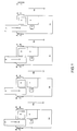
- Fig. 1 is a diagrammatic representation of an example of a check-out system as often used in shops designed as supermarkets, e.g. food shops.
- the check-out system shown comprises a plurality of juxtaposed cash blocks la through 1d. Located between each pair of juxtaposed cash blocks is a gangway 9a through 9d, via which the customers can go to the exit, after having paid for the selected goods at the cash desk.
- the cash blocks may be constructed in different ways.
- the cash blocks comprise a conveyor belt 2, a (computer) cash register, a bar code scanner and/or a pair of scales 5 and a seat 4 for the cash personnel.
- there is generated in the gangway between two cash blocks a detection field capable of detecting electronic or magnetic responders attached to the shop goods when the shop goods are conveyed through the gangway instead of via the conveyor belt past the cash personnel.
- the detection field is generated by means of antennas 6 arranged on both sides of each gangway.
- the antennas are mostly accommodated in an antenna pillar disposed against a cash block or (partly) put into a recess in a cash block.
- the antennas are preferably shielded from the associated cash block.
- the figure shows on both sides of each cash block a receiving antenna 7 and a transmitting antenna 8.
- a transmitting unit and a receiving unit connected with respectively the receiving antenna and the transmitting antenna.
- each receiving antenna is connected with a separate associated receiver not connected with other receiving antennas, it is always certain upon detection of a label in which passageway detection took place.
- the sensitivity of a check-out system to the remaining undesirable effects of a multipad propagation caused by, inter alia, coupling of transmitters, via conductors and apparatuses, with receivers on the other side of a cash block, and by parasitic resonances of conductors in the cash blocks can be further reduced.
- the same pillar type is mounted on both sides of a cash block: alternately, therefore, two transmitterg pillars or two receiver pillars for each cash desk.
- the detection range and the sensitivity to undesirable coupling via the cash block between two pillars of the same type are much lower than between a transmitterg and a receiver pillar. Consequently, labelled goods on the conveyor belt of the cash block give less cause to false alarm.
- Cash block 1 a is provided on both sides with receiving antennas, cash block 1 b with transmitting antennas etc.
- each antenna in a check-out system is connected with the transmitter or receiver electronics belonging to that antenna, which electronics may or may not be mounted in the antenna pillar.
- a cash block therefore contains alternately two transmitter and receiver electronics units.
- a strong simplification may be realized by arranging instead of two electronics units of the transmitter or receiver type for each cash block only one electronics unit which is connected to the two antennas on both sides of the cash block.
- the electronics units may be connected via cables 12.
- Such a configuration is diagrammatically shown in Fig. 2.
- Cash blocks 1a and 1c are each provided with a receiving unit connected via coaxial cables 11 with the receiving antennas 7, and cash blocks 1 b and 1 d are each provided with a transmitting unit 18 connected via coaxial cables 11 with the two transmitting antennas 8 of each cash block.
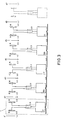
- Practical examples are diagrammatically shown in Fig. 3 and Fig. 4.
- the two antennas 6 with the shielding 10 of a cash block 1 are parallel connected to the corresponding electronics unit 17 or 18, e.g. via a coupling transformer, a power splitter/combiner 13 or a directional coupling.
- the transmitting units 18a, 18b i.e. alternately switching them on by means of suitable control means 20, according to the principle described for a detached row of pillars, simultaneous detection is realized in the passageways on both sides of the cash blocks with a transmitting unit, cash blocks with switched-on and -off transmitters alternating with each other.
- the detection is alternately switched on in the passageways d1, d2, d5, d6, d9, d10 etc. or in the passageways d3, d4, d7, d8, d11, d 12 etc.
- phase detection means in the receivers in which passageway detection takes place. With this information the signalling device belonging to the passageway is controlled. The detection in the passageways is therefore alternately switched on two by two.
- This embodiment results in some electric losses caused by the parallel connection of two antennas via an impedance transformer which becomes evident in a decrease of detection sensitivity of 2 x 3 dB.
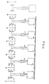
- Fig. 4 shows a schematic diagram.
- a preferably electronic switch member 14 or 15 is interposed between two antennas 6 and a transmitting unit 18 or receiving unit 17.
- the switch member behaves like a rapid relay with a change-over contact and may be realized , e.g., with PIN diodes or FET as a switch member. At low multiplex frequences an electromechanical relay is also possible.
- the switch member takes the place of the coupling transformer 13 which is used for parallel connection of two antennas.
- reaction velocity and sensitivity set a lower limit to the time a label signal of minimum strength must be present to enable reliable detection. Also, complicated cabling would be necessary.
- cost price and system performance may be balanced against each other.
- the invention can also be applied without co-using shielded antennas.
- the invention is applicable if in the space between two passageways no detection of responders is desirable or if the space between two passageways is blocked by a blocking element other than a cash block.
- a blocking element other than a cash block.
- the receivers or the transmitters or both can be controlled according to a multiplex system.
- a transmitting unit like 18a can be used with on both sides an obstacle having a receiving unit. In that case the transmitting unitcould be switched on continuously, while the receiving units are switched on and off alternately.
- the shields 10 shown in the figures may comprise panels of metal gauze or other suitable shielding members.
Landscapes
- Physics & Mathematics (AREA)
- Engineering & Computer Science (AREA)
- Automation & Control Theory (AREA)
- Computer Security & Cryptography (AREA)
- Electromagnetism (AREA)
- General Physics & Mathematics (AREA)
- Signal Processing (AREA)
- Burglar Alarm Systems (AREA)
Applications Claiming Priority (2)
| Application Number | Priority Date | Filing Date | Title |
|---|---|---|---|
| NL9300124A NL9300124A (nl) | 1993-01-22 | 1993-01-22 | Verbeterde antenneconfiguratie bij winkeldiefstaldetectiesystemen in supermarkten. |
| NL9300124 | 1993-01-22 |
Publications (2)
| Publication Number | Publication Date |
|---|---|
| EP0608039A1 true EP0608039A1 (de) | 1994-07-27 |
| EP0608039B1 EP0608039B1 (de) | 1998-09-02 |
Family
ID=19861956
Family Applications (1)
| Application Number | Title | Priority Date | Filing Date |
|---|---|---|---|
| EP19940200142 Expired - Lifetime EP0608039B1 (de) | 1993-01-22 | 1994-01-21 | Ladendiebstahldetektierungssystem, insbesondere geeignet für den Gebrauch in Supermärkten, und ein Ladenentwurf mit solchem System |
Country Status (3)
| Country | Link |
|---|---|
| EP (1) | EP0608039B1 (de) |
| DE (1) | DE69412871T2 (de) |
| NL (1) | NL9300124A (de) |
Cited By (3)
| Publication number | Priority date | Publication date | Assignee | Title |
|---|---|---|---|---|
| US7119692B2 (en) | 2003-11-10 | 2006-10-10 | 3M Innovative Properties Company | System for detecting radio-frequency identification tags |
| US7372364B2 (en) | 2003-11-10 | 2008-05-13 | 3M Innovative Properties Company | Algorithm for RFID security |
| FR2981547A1 (fr) * | 2011-10-24 | 2013-04-26 | Jean Yves Patachek | Systeme rapide de simulation de ce que peut donner un nouveau bracelet montre sans avoir besoin de l'essayer comme auparavant |
Citations (2)
| Publication number | Priority date | Publication date | Assignee | Title |
|---|---|---|---|---|
| EP0035660A2 (de) * | 1980-02-19 | 1981-09-16 | Knogo Corporation | Detektion von Gegenständen in benachbarten Fussgängerpassagen |
| WO1991017533A1 (en) * | 1990-05-01 | 1991-11-14 | N.V. Nederlandsche Apparatenfabriek Nedap | Shoplifting detection system with partly screened antennas |
-
1993
- 1993-01-22 NL NL9300124A patent/NL9300124A/nl not_active Application Discontinuation
-
1994
- 1994-01-21 EP EP19940200142 patent/EP0608039B1/de not_active Expired - Lifetime
- 1994-01-21 DE DE1994612871 patent/DE69412871T2/de not_active Expired - Fee Related
Patent Citations (2)
| Publication number | Priority date | Publication date | Assignee | Title |
|---|---|---|---|---|
| EP0035660A2 (de) * | 1980-02-19 | 1981-09-16 | Knogo Corporation | Detektion von Gegenständen in benachbarten Fussgängerpassagen |
| WO1991017533A1 (en) * | 1990-05-01 | 1991-11-14 | N.V. Nederlandsche Apparatenfabriek Nedap | Shoplifting detection system with partly screened antennas |
Cited By (4)
| Publication number | Priority date | Publication date | Assignee | Title |
|---|---|---|---|---|
| US7119692B2 (en) | 2003-11-10 | 2006-10-10 | 3M Innovative Properties Company | System for detecting radio-frequency identification tags |
| US7372364B2 (en) | 2003-11-10 | 2008-05-13 | 3M Innovative Properties Company | Algorithm for RFID security |
| US7405663B2 (en) | 2003-11-10 | 2008-07-29 | 3M Innovative Properties Company | System for detecting radio-frequency identification tags |
| FR2981547A1 (fr) * | 2011-10-24 | 2013-04-26 | Jean Yves Patachek | Systeme rapide de simulation de ce que peut donner un nouveau bracelet montre sans avoir besoin de l'essayer comme auparavant |
Also Published As
| Publication number | Publication date |
|---|---|
| NL9300124A (nl) | 1994-08-16 |
| DE69412871T2 (de) | 1999-04-08 |
| EP0608039B1 (de) | 1998-09-02 |
| DE69412871D1 (de) | 1998-10-15 |
Similar Documents
| Publication | Publication Date | Title |
|---|---|---|
| EP0316963B1 (de) | Mit mehreren Frequenzen arbeitendes Ladendiebstahl-Sicherungssystem | |
| CA1111123A (en) | Electronic theft detection system for monitoring wide passageways | |
| EP1242985B1 (de) | System zur detektierung und ortung von sicherheitsetiketten | |
| US6703935B1 (en) | Antenna arrangement for RFID smart tags | |
| EP0237950B1 (de) | Verfahren und Einrichtung zum Deaktivieren der Etiketten von Warenüberwachungssystemen vom elektromagnetischen Typ | |
| US6696954B2 (en) | Antenna array for smart RFID tags | |
| US5142292A (en) | Coplanar multiple loop antenna for electronic article surveillance systems | |
| US6154135A (en) | Apparatus for capturing data and deactivating electronic article surveillance tags | |
| US7172123B2 (en) | Combined data reader and electronic article surveillance (EAS) system | |
| EP0496610A2 (de) | Abfragestation zur Identifizierung mit separaten Sende- und Empfangsantennen | |
| EP0169649A2 (de) | Vorrichtung und Verfahren zur Verminderung von Diebstählen aus einem Warenhaus | |
| WO2008024429A2 (en) | Radio frequency identification shelf antenna with a distributed pattern for localized tag detection | |
| US20100123559A1 (en) | Apparatus and Method Facilitating Communication Between Components of a Radio Frequency Identification System | |
| CA2036378A1 (en) | Proximity detecting apparatus | |
| US5367291A (en) | Shoplifting detection system with partly screened antennas | |
| KR0169752B1 (ko) | 식당의 식기분류방법 및 그 분류방법에 이용하는 식기 및 정산장치 및 식기 구분장치 | |
| EP0704829B1 (de) | System zur Empfängereingangssteuerung für ein elektronisches Warenüberwachungssystem, das zur dynamischen Optimierung ein Expertensystem verwendet | |
| EP0608039B1 (de) | Ladendiebstahldetektierungssystem, insbesondere geeignet für den Gebrauch in Supermärkten, und ein Ladenentwurf mit solchem System | |
| NL1009268C2 (nl) | Elektronisch artikelinformatiestelsel voor winkels. | |
| CN100410960C (zh) | 检测射频辨识标签的系统 | |
| GB2317075A (en) | Weighing device with integral tag deactivator | |
| AU716217B2 (en) | Pulsed electronic article surveillance device employing expert system techniques for dynamic optimization | |
| HK1017155A (en) | Method and apparatus for detecting an rfid tag signal |
Legal Events
| Date | Code | Title | Description |
|---|---|---|---|
| PUAI | Public reference made under article 153(3) epc to a published international application that has entered the european phase |
Free format text: ORIGINAL CODE: 0009012 |
|
| AK | Designated contracting states |
Kind code of ref document: A1 Designated state(s): CH DE FR GB LI NL |
|
| 17P | Request for examination filed |
Effective date: 19940920 |
|
| 17Q | First examination report despatched |
Effective date: 19970314 |
|
| GRAG | Despatch of communication of intention to grant |
Free format text: ORIGINAL CODE: EPIDOS AGRA |
|
| GRAG | Despatch of communication of intention to grant |
Free format text: ORIGINAL CODE: EPIDOS AGRA |
|
| GRAH | Despatch of communication of intention to grant a patent |
Free format text: ORIGINAL CODE: EPIDOS IGRA |
|
| GRAH | Despatch of communication of intention to grant a patent |
Free format text: ORIGINAL CODE: EPIDOS IGRA |
|
| GRAA | (expected) grant |
Free format text: ORIGINAL CODE: 0009210 |
|
| AK | Designated contracting states |
Kind code of ref document: B1 Designated state(s): CH DE FR GB LI NL |
|
| PG25 | Lapsed in a contracting state [announced via postgrant information from national office to epo] |
Ref country code: LI Free format text: LAPSE BECAUSE OF FAILURE TO SUBMIT A TRANSLATION OF THE DESCRIPTION OR TO PAY THE FEE WITHIN THE PRESCRIBED TIME-LIMIT Effective date: 19980902 Ref country code: FR Free format text: LAPSE BECAUSE OF FAILURE TO SUBMIT A TRANSLATION OF THE DESCRIPTION OR TO PAY THE FEE WITHIN THE PRESCRIBED TIME-LIMIT Effective date: 19980902 Ref country code: CH Free format text: LAPSE BECAUSE OF FAILURE TO SUBMIT A TRANSLATION OF THE DESCRIPTION OR TO PAY THE FEE WITHIN THE PRESCRIBED TIME-LIMIT Effective date: 19980902 |
|
| REG | Reference to a national code |
Ref country code: CH Ref legal event code: EP |
|
| REF | Corresponds to: |
Ref document number: 69412871 Country of ref document: DE Date of ref document: 19981015 |
|
| PG25 | Lapsed in a contracting state [announced via postgrant information from national office to epo] |
Ref country code: GB Free format text: LAPSE BECAUSE OF NON-PAYMENT OF DUE FEES Effective date: 19990121 |
|
| EN | Fr: translation not filed | ||
| REG | Reference to a national code |
Ref country code: CH Ref legal event code: PL |
|
| PLBE | No opposition filed within time limit |
Free format text: ORIGINAL CODE: 0009261 |
|
| STAA | Information on the status of an ep patent application or granted ep patent |
Free format text: STATUS: NO OPPOSITION FILED WITHIN TIME LIMIT |
|
| 26N | No opposition filed | ||
| GBPC | Gb: european patent ceased through non-payment of renewal fee |
Effective date: 19990121 |
|
| PGFP | Annual fee paid to national office [announced via postgrant information from national office to epo] |
Ref country code: NL Payment date: 20040116 Year of fee payment: 11 |
|
| PGFP | Annual fee paid to national office [announced via postgrant information from national office to epo] |
Ref country code: DE Payment date: 20040212 Year of fee payment: 11 |
|
| PG25 | Lapsed in a contracting state [announced via postgrant information from national office to epo] |
Ref country code: NL Free format text: LAPSE BECAUSE OF NON-PAYMENT OF DUE FEES Effective date: 20050801 |
|
| PG25 | Lapsed in a contracting state [announced via postgrant information from national office to epo] |
Ref country code: DE Free format text: LAPSE BECAUSE OF NON-PAYMENT OF DUE FEES Effective date: 20050802 |
|
| NLV4 | Nl: lapsed or anulled due to non-payment of the annual fee |
Effective date: 20050801 |