EP0608236B1 - Kontinuierliche Polytetrafluoroethylen-Filamente - Google Patents
Kontinuierliche Polytetrafluoroethylen-Filamente Download PDFInfo
- Publication number
- EP0608236B1 EP0608236B1 EP19920914054 EP92914054A EP0608236B1 EP 0608236 B1 EP0608236 B1 EP 0608236B1 EP 19920914054 EP19920914054 EP 19920914054 EP 92914054 A EP92914054 A EP 92914054A EP 0608236 B1 EP0608236 B1 EP 0608236B1
- Authority
- EP
- European Patent Office
- Prior art keywords
- continuous
- fiber
- sheet
- ptfe
- continuous fiber
- Prior art date
- Legal status (The legal status is an assumption and is not a legal conclusion. Google has not performed a legal analysis and makes no representation as to the accuracy of the status listed.)
- Expired - Lifetime
Links
Images



Classifications
-
- D—TEXTILES; PAPER
- D01—NATURAL OR MAN-MADE THREADS OR FIBRES; SPINNING
- D01D—MECHANICAL METHODS OR APPARATUS IN THE MANUFACTURE OF ARTIFICIAL FILAMENTS, THREADS, FIBRES, BRISTLES OR RIBBONS
- D01D5/00—Formation of filaments, threads, or the like
- D01D5/24—Formation of filaments, threads, or the like with a hollow structure; Spinnerette packs therefor
- D01D5/247—Discontinuous hollow structure or microporous structure
-
- B—PERFORMING OPERATIONS; TRANSPORTING
- B29—WORKING OF PLASTICS; WORKING OF SUBSTANCES IN A PLASTIC STATE IN GENERAL
- B29C—SHAPING OR JOINING OF PLASTICS; SHAPING OF MATERIAL IN A PLASTIC STATE, NOT OTHERWISE PROVIDED FOR; AFTER-TREATMENT OF THE SHAPED PRODUCTS, e.g. REPAIRING
- B29C53/00—Shaping by bending, folding, twisting, straightening or flattening; Apparatus therefor
- B29C53/56—Winding and joining, e.g. winding spirally
- B29C53/58—Winding and joining, e.g. winding spirally helically
-
- B—PERFORMING OPERATIONS; TRANSPORTING
- B29—WORKING OF PLASTICS; WORKING OF SUBSTANCES IN A PLASTIC STATE IN GENERAL
- B29C—SHAPING OR JOINING OF PLASTICS; SHAPING OF MATERIAL IN A PLASTIC STATE, NOT OTHERWISE PROVIDED FOR; AFTER-TREATMENT OF THE SHAPED PRODUCTS, e.g. REPAIRING
- B29C53/00—Shaping by bending, folding, twisting, straightening or flattening; Apparatus therefor
- B29C53/56—Winding and joining, e.g. winding spirally
- B29C53/58—Winding and joining, e.g. winding spirally helically
- B29C53/583—Winding and joining, e.g. winding spirally helically for making tubular articles with particular features
- B29C53/585—Winding and joining, e.g. winding spirally helically for making tubular articles with particular features the cross-section varying along their axis, e.g. tapered, with ribs, or threads, with socket-ends
-
- B—PERFORMING OPERATIONS; TRANSPORTING
- B29—WORKING OF PLASTICS; WORKING OF SUBSTANCES IN A PLASTIC STATE IN GENERAL
- B29C—SHAPING OR JOINING OF PLASTICS; SHAPING OF MATERIAL IN A PLASTIC STATE, NOT OTHERWISE PROVIDED FOR; AFTER-TREATMENT OF THE SHAPED PRODUCTS, e.g. REPAIRING
- B29C55/00—Shaping by stretching, e.g. drawing through a die; Apparatus therefor
- B29C55/005—Shaping by stretching, e.g. drawing through a die; Apparatus therefor characterised by the choice of materials
-
- B—PERFORMING OPERATIONS; TRANSPORTING
- B31—MAKING ARTICLES OF PAPER, CARDBOARD OR MATERIAL WORKED IN A MANNER ANALOGOUS TO PAPER; WORKING PAPER, CARDBOARD OR MATERIAL WORKED IN A MANNER ANALOGOUS TO PAPER
- B31F—MECHANICAL WORKING OR DEFORMATION OF PAPER, CARDBOARD OR MATERIAL WORKED IN A MANNER ANALOGOUS TO PAPER
- B31F1/00—Mechanical deformation without removing material, e.g. in combination with laminating
- B31F1/0003—Shaping by bending, folding, twisting, straightening, flattening or rim-rolling; Shaping by bending, folding or rim-rolling combined with joining; Apparatus therefor
- B31F1/0045—Bending or folding combined with joining
- B31F1/0048—Bending plates, sheets or webs at right angles to the axis of the article being formed and joining the edges
- B31F1/0074—Making essentially non-hollow profiles, e.g. rods, ropes, cords
-
- D—TEXTILES; PAPER
- D01—NATURAL OR MAN-MADE THREADS OR FIBRES; SPINNING
- D01D—MECHANICAL METHODS OR APPARATUS IN THE MANUFACTURE OF ARTIFICIAL FILAMENTS, THREADS, FIBRES, BRISTLES OR RIBBONS
- D01D5/00—Formation of filaments, threads, or the like
-
- D—TEXTILES; PAPER
- D01—NATURAL OR MAN-MADE THREADS OR FIBRES; SPINNING
- D01F—CHEMICAL FEATURES IN THE MANUFACTURE OF ARTIFICIAL FILAMENTS, THREADS, FIBRES, BRISTLES OR RIBBONS; APPARATUS SPECIALLY ADAPTED FOR THE MANUFACTURE OF CARBON FILAMENTS
- D01F6/00—Monocomponent artificial filaments or the like of synthetic polymers; Manufacture thereof
- D01F6/02—Monocomponent artificial filaments or the like of synthetic polymers; Manufacture thereof from homopolymers obtained by reactions only involving carbon-to-carbon unsaturated bonds
- D01F6/08—Monocomponent artificial filaments or the like of synthetic polymers; Manufacture thereof from homopolymers obtained by reactions only involving carbon-to-carbon unsaturated bonds from polymers of halogenated hydrocarbons
- D01F6/12—Monocomponent artificial filaments or the like of synthetic polymers; Manufacture thereof from homopolymers obtained by reactions only involving carbon-to-carbon unsaturated bonds from polymers of halogenated hydrocarbons from polymers of fluorinated hydrocarbons
-
- F—MECHANICAL ENGINEERING; LIGHTING; HEATING; WEAPONS; BLASTING
- F16—ENGINEERING ELEMENTS AND UNITS; GENERAL MEASURES FOR PRODUCING AND MAINTAINING EFFECTIVE FUNCTIONING OF MACHINES OR INSTALLATIONS; THERMAL INSULATION IN GENERAL
- F16J—PISTONS; CYLINDERS; SEALINGS
- F16J15/00—Sealings
- F16J15/02—Sealings between relatively-stationary surfaces
- F16J15/06—Sealings between relatively-stationary surfaces with solid packing compressed between sealing surfaces
- F16J15/10—Sealings between relatively-stationary surfaces with solid packing compressed between sealing surfaces with non-metallic packing
- F16J15/104—Sealings between relatively-stationary surfaces with solid packing compressed between sealing surfaces with non-metallic packing characterised by structure
-
- B—PERFORMING OPERATIONS; TRANSPORTING
- B29—WORKING OF PLASTICS; WORKING OF SUBSTANCES IN A PLASTIC STATE IN GENERAL
- B29K—INDEXING SCHEME ASSOCIATED WITH SUBCLASSES B29B, B29C OR B29D, RELATING TO MOULDING MATERIALS OR TO MATERIALS FOR MOULDS, REINFORCEMENTS, FILLERS OR PREFORMED PARTS, e.g. INSERTS
- B29K2027/00—Use of polyvinylhalogenides or derivatives thereof as moulding material
- B29K2027/12—Use of polyvinylhalogenides or derivatives thereof as moulding material containing fluorine
- B29K2027/18—PTFE, i.e. polytetrafluoroethylene, e.g. ePTFE, i.e. expanded polytetrafluoroethylene
-
- B—PERFORMING OPERATIONS; TRANSPORTING
- B29—WORKING OF PLASTICS; WORKING OF SUBSTANCES IN A PLASTIC STATE IN GENERAL
- B29L—INDEXING SCHEME ASSOCIATED WITH SUBCLASS B29C, RELATING TO PARTICULAR ARTICLES
- B29L2031/00—Other particular articles
- B29L2031/26—Sealing devices, e.g. packaging for pistons or pipe joints
- B29L2031/265—Packings, Gaskets
-
- Y—GENERAL TAGGING OF NEW TECHNOLOGICAL DEVELOPMENTS; GENERAL TAGGING OF CROSS-SECTIONAL TECHNOLOGIES SPANNING OVER SEVERAL SECTIONS OF THE IPC; TECHNICAL SUBJECTS COVERED BY FORMER USPC CROSS-REFERENCE ART COLLECTIONS [XRACs] AND DIGESTS
- Y10—TECHNICAL SUBJECTS COVERED BY FORMER USPC
- Y10S—TECHNICAL SUBJECTS COVERED BY FORMER USPC CROSS-REFERENCE ART COLLECTIONS [XRACs] AND DIGESTS
- Y10S57/00—Textiles: spinning, twisting, and twining
- Y10S57/903—Sewing threads
-
- Y—GENERAL TAGGING OF NEW TECHNOLOGICAL DEVELOPMENTS; GENERAL TAGGING OF CROSS-SECTIONAL TECHNOLOGIES SPANNING OVER SEVERAL SECTIONS OF THE IPC; TECHNICAL SUBJECTS COVERED BY FORMER USPC CROSS-REFERENCE ART COLLECTIONS [XRACs] AND DIGESTS
- Y10—TECHNICAL SUBJECTS COVERED BY FORMER USPC
- Y10S—TECHNICAL SUBJECTS COVERED BY FORMER USPC CROSS-REFERENCE ART COLLECTIONS [XRACs] AND DIGESTS
- Y10S57/00—Textiles: spinning, twisting, and twining
- Y10S57/907—Foamed and/or fibrillated
-
- Y—GENERAL TAGGING OF NEW TECHNOLOGICAL DEVELOPMENTS; GENERAL TAGGING OF CROSS-SECTIONAL TECHNOLOGIES SPANNING OVER SEVERAL SECTIONS OF THE IPC; TECHNICAL SUBJECTS COVERED BY FORMER USPC CROSS-REFERENCE ART COLLECTIONS [XRACs] AND DIGESTS
- Y10—TECHNICAL SUBJECTS COVERED BY FORMER USPC
- Y10T—TECHNICAL SUBJECTS COVERED BY FORMER US CLASSIFICATION
- Y10T428/00—Stock material or miscellaneous articles
- Y10T428/29—Coated or structually defined flake, particle, cell, strand, strand portion, rod, filament, macroscopic fiber or mass thereof
-
- Y—GENERAL TAGGING OF NEW TECHNOLOGICAL DEVELOPMENTS; GENERAL TAGGING OF CROSS-SECTIONAL TECHNOLOGIES SPANNING OVER SEVERAL SECTIONS OF THE IPC; TECHNICAL SUBJECTS COVERED BY FORMER USPC CROSS-REFERENCE ART COLLECTIONS [XRACs] AND DIGESTS
- Y10—TECHNICAL SUBJECTS COVERED BY FORMER USPC
- Y10T—TECHNICAL SUBJECTS COVERED BY FORMER US CLASSIFICATION
- Y10T428/00—Stock material or miscellaneous articles
- Y10T428/29—Coated or structually defined flake, particle, cell, strand, strand portion, rod, filament, macroscopic fiber or mass thereof
- Y10T428/2913—Rod, strand, filament or fiber
-
- Y—GENERAL TAGGING OF NEW TECHNOLOGICAL DEVELOPMENTS; GENERAL TAGGING OF CROSS-SECTIONAL TECHNOLOGIES SPANNING OVER SEVERAL SECTIONS OF THE IPC; TECHNICAL SUBJECTS COVERED BY FORMER USPC CROSS-REFERENCE ART COLLECTIONS [XRACs] AND DIGESTS
- Y10—TECHNICAL SUBJECTS COVERED BY FORMER USPC
- Y10T—TECHNICAL SUBJECTS COVERED BY FORMER US CLASSIFICATION
- Y10T428/00—Stock material or miscellaneous articles
- Y10T428/29—Coated or structually defined flake, particle, cell, strand, strand portion, rod, filament, macroscopic fiber or mass thereof
- Y10T428/2913—Rod, strand, filament or fiber
- Y10T428/2922—Nonlinear [e.g., crimped, coiled, etc.]
- Y10T428/2924—Composite
-
- Y—GENERAL TAGGING OF NEW TECHNOLOGICAL DEVELOPMENTS; GENERAL TAGGING OF CROSS-SECTIONAL TECHNOLOGIES SPANNING OVER SEVERAL SECTIONS OF THE IPC; TECHNICAL SUBJECTS COVERED BY FORMER USPC CROSS-REFERENCE ART COLLECTIONS [XRACs] AND DIGESTS
- Y10—TECHNICAL SUBJECTS COVERED BY FORMER USPC
- Y10T—TECHNICAL SUBJECTS COVERED BY FORMER US CLASSIFICATION
- Y10T428/00—Stock material or miscellaneous articles
- Y10T428/29—Coated or structually defined flake, particle, cell, strand, strand portion, rod, filament, macroscopic fiber or mass thereof
- Y10T428/2913—Rod, strand, filament or fiber
- Y10T428/2922—Nonlinear [e.g., crimped, coiled, etc.]
- Y10T428/2925—Helical or coiled
-
- Y—GENERAL TAGGING OF NEW TECHNOLOGICAL DEVELOPMENTS; GENERAL TAGGING OF CROSS-SECTIONAL TECHNOLOGIES SPANNING OVER SEVERAL SECTIONS OF THE IPC; TECHNICAL SUBJECTS COVERED BY FORMER USPC CROSS-REFERENCE ART COLLECTIONS [XRACs] AND DIGESTS
- Y10—TECHNICAL SUBJECTS COVERED BY FORMER USPC
- Y10T—TECHNICAL SUBJECTS COVERED BY FORMER US CLASSIFICATION
- Y10T428/00—Stock material or miscellaneous articles
- Y10T428/29—Coated or structually defined flake, particle, cell, strand, strand portion, rod, filament, macroscopic fiber or mass thereof
- Y10T428/2913—Rod, strand, filament or fiber
- Y10T428/2933—Coated or with bond, impregnation or core
-
- Y—GENERAL TAGGING OF NEW TECHNOLOGICAL DEVELOPMENTS; GENERAL TAGGING OF CROSS-SECTIONAL TECHNOLOGIES SPANNING OVER SEVERAL SECTIONS OF THE IPC; TECHNICAL SUBJECTS COVERED BY FORMER USPC CROSS-REFERENCE ART COLLECTIONS [XRACs] AND DIGESTS
- Y10—TECHNICAL SUBJECTS COVERED BY FORMER USPC
- Y10T—TECHNICAL SUBJECTS COVERED BY FORMER US CLASSIFICATION
- Y10T428/00—Stock material or miscellaneous articles
- Y10T428/29—Coated or structually defined flake, particle, cell, strand, strand portion, rod, filament, macroscopic fiber or mass thereof
- Y10T428/2913—Rod, strand, filament or fiber
- Y10T428/2933—Coated or with bond, impregnation or core
- Y10T428/2936—Wound or wrapped core or coating [i.e., spiral or helical]
-
- Y—GENERAL TAGGING OF NEW TECHNOLOGICAL DEVELOPMENTS; GENERAL TAGGING OF CROSS-SECTIONAL TECHNOLOGIES SPANNING OVER SEVERAL SECTIONS OF THE IPC; TECHNICAL SUBJECTS COVERED BY FORMER USPC CROSS-REFERENCE ART COLLECTIONS [XRACs] AND DIGESTS
- Y10—TECHNICAL SUBJECTS COVERED BY FORMER USPC
- Y10T—TECHNICAL SUBJECTS COVERED BY FORMER US CLASSIFICATION
- Y10T428/00—Stock material or miscellaneous articles
- Y10T428/31504—Composite [nonstructural laminate]
- Y10T428/3154—Of fluorinated addition polymer from unsaturated monomers
- Y10T428/31544—Addition polymer is perhalogenated
Definitions
- This invention relates to a novel continuous polytetrafluoroethylene fiber having a substantially round profile.
- Polytetrafluoroethylene (PTFE) fiber is a desirable commercial form of PTFE, however, manufacture of continuous strong fibers from PTFE resin is a difficult process. Conventional fiber forming techniques used in production of fibers from other polymeric materials are of little use in producing PTFE fibers.
- slit film fibers of expanded microporous PTFE have a tendency to fibrillate or fray at the slit edges of the fiber.
- slit film fibers of expanded microporous PTFE are not round but are rectangular in cross-section. Therefore, to obtain a more uniform appearance in slit film fibers of expanded microporous PTFE slit film fibers of expanded microporous PTFE are twisted along their longitudinal axis producing twisted fibers.
- Twisted fibers give the illusion of appearing more round in cross-section than untwisted fibers by presenting a mixture of sides of the rectangular cross-section of the fibers to the viewer which is especially desirable when slit film fibers of expanded microporous PTFE are used in the production of knitted or woven fabrics.
- the fibers may be twisted to the extent that tubular structures are produced. It is desirable that fibers have uniform cross-sections along their lengths so that fabrics produced from these fibers contain interstices of an uniform and predictable nature. Fabrics containing interstices of a uniform and predictable nature when used as a filter element exhibit a constant filtration efficiency across the surface of the fabric.
- slit film fibres of expanded microporous PTFE are difficult to produce with a consistent twist along the length of the fibres, thereby resulting in fibres with non-uniform cross sections along their length. Fibres having inconsistent twists, as well as fabrics produced from these fibres, are considered flawed when visually inspected, and are of limited utility as a filter element.
- US 2,363,457 describes a process for making polyvinyl alcohol threads which comprises steam heating a tape role of the material to make it sticky and helically winding the tape upon itself to make the required thread.
- US 3,126,699 describes a process suitable for making a thread of any organic, thermoplastic, resinous material which similarly involves helically winding a tape of the material upon itself.
- the present invention relates to a continuous fiber comprising a helically rolled self-adhered continuous sheet of polytetrafluoroethylene, said fiber having an outside surface with a substantially round profile and a single spiralling external seam.
- the continuous sheet of PTFE may be filled with particulate fillers or coated with polymeric materials prior to production of the continuous substantially round PTFE fiber.
- the continuous sheet of PTFE may be used to combine other elements, i.e. filamentary elements or sheet-like elements, within the continuous substantially round PTFE fiber.
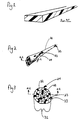
- Figure 1 depicts a prior art slit film fiber.
- Figure 2 depicts the inventive fiber in a perspective view.
- Figure 3 depicts the inventive fiber in a cross-sectional view.
- Figure 4 depicts other embodiments of the inventive fiber in cross-sectional views.
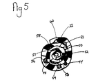
- Figure 5 depicts another embodiment of the inventive fiber in cross-sectional view.
- Figure 6 depicts drums of a machine used to produce the invention in cross-sectional view.
- Figure 7 is a perspective view of a driven drum in Figure 6.
- Figure 8 depicts another embodiment of the inventive fiber in perspective view.
- Figure 9 depicts still another embodiment of the inventive fiber in perspective view.
- the invention is directed to articles of manufacture which are continuous polytetrafluoroethylene (PTFE) fibers, i.e . strands, threads, rods, or tubes having an outside surface with a substantially round profile and a single spiralling seam.
- the fiber is produced from a continuous sheet of PTFE, preferably from a continuous sheet of microporous PTFE, more preferably from a continuous sheet of expanded microporous PTFE as taught in U.S. Patents 3,953,566 and 4,187,390 all to Gore and incorporated herein by reference.
- the continuous sheet of PTFE has a width at least 10 times its thickness.
- the continuous sheet of PTFE is expanded microporous PTFE
- the continuous sheet of expanded microporous PTFE may be either biaxially expanded, i.e . expanded in both longitudinal and transverse directions or uniaxially expanded in only a longitudinal direction.
- FIG. 3 a cross-sectional view of a continuous PTFE fiber 21 of the instant invention taken along orientation line 2-2 in Figure 2 is depicted.
- the continuous PTFE fiber is comprised of a helically rolled self-adhered continuous sheet of PTFE 32 .
- the continuous PTFE fiber has an outside surface 24 with a substantially round profile 31 and a single seam 23 .
- the single seam is formed by adherence of the outside edge 33 of the helically rolled self-adhered continuous sheet of PTFE 32 to the outside surface 24 of the continuous PTFE fiber.
- FIG. 2 a perspective view of the continuous fiber 21 of the instant invention is depicted.
- the single seam 23 is clearly shown spiralling along the length of the continuous PTFE fiber.
- Helically rolled is defined herein as a spiral structure formed through wrapping the continuous PTFE sheet about a central longitudinal axis of the inventive fiber in the longitudinal direction of the inventive fiber.
- FIG. 6 a cross section of drums of a machine used to produce the continuous PTFE fiber of the instant invention is depicted.
- the machine is comprised of a controlling means 63 and a driven drum 64 having an outside surface.
- the controlling means 63 is depicted as a drum, however, the controlling means may also include dancer arms or eyelet guides that aid in controlling the continuous PTFE sheet 66 as it contacts the outside surface of the driven drum 64 .
- the continuous PTFE sheet 66 is passed around the controlling means 63 and is carefully fed onto the outside surface of the driven drum 64 .
- the outside surface of the driven drum is conditioned in such a manner so that the continuous sheet of PTFE is tightly held against the outside surface of the driven drum.
- the surface of the driven drum should be of a metal, preferably of a heated metal.
- the driven drum is rotated about an axis by a drive means so that the continuous PTFE sheet is caused to move circumferentially along the outside surface of the driven drum.
- FIG. 7 a perspective view of the driven drum 64 perpendicular to orientation line 65 is depicted. While the continuous PTFE sheet 66 is maintained in contact and tightly held by the surface of the driven drum 64 , an edge 74 of the continuous sheet of PTFE is removed from contact with the outside surface of the driven drum and the edge is rolled over and is caused to contact the continuous PTFE sheet that is still in contact and tightly held by the surface of the driven drum. The removed edge contacts the continuous PTFE sheet at an angle 71 to a longitudinal axis of the continuous PTFE sheet 72 . The surface of the continuous PTFE sheet is conditioned in such a manner so that the removed edge adheres to the surface of the PTFE sheet tightly held to the surface of the driven drum.
- the driven drum is rotated by the drive means and the continuous PTFE sheet is caused to move circumferentially along the surface of the driven drum, the removed edge adhering to the surface of the continuous PTFE sheet is thereby rolled upon itself producing a continuous PTFE fiber 21 which is removed from the outside surface of the driven drum at an angle 73 to the longitudinal axis of the continuous PTFE sheet.
- the angle at which the continuous PTFE fiber is removed from the driven drum is not necessarily the same angle that the removed edge of the PTFE sheet contacts the surface of the PTFE sheet since a greater angle may be necessary to cause the continuous PTFE sheet to initially helically roll than is necessary to remove the continuous round PTFE fiber from the driven drum once fiber formation has begun.
- Heat, applied by the driven drum surface may be used to increase the adhesion between the multiple layers of PTFE of the continuous PTFE fiber during formation of the continuous PTFE fiber.
- the continuous PTFE sheet is a sheet of expanded microporous PTFE
- the driven drum may be heated to a temperature in excess of 327°C more preferably in excess of 342°C so that the PTFE sheet is subjected to a heat treatment amorphous locking process as taught in U.S. Patent 3,953,566 to Gore , column 3, lines 49-55, incorporated herein by reference.
- the heat treatment amorphous locking process entails exposing the continuous sheet of expanded microporous PTFE to temperatures in excess of 327°C thereby reducing the crystalline content of the continuous sheet of expanded microporous PTFE.
- the continuous sheet of expanded microporous PTFE may have previously been subjected to the heat treatment amorphous locking process. Previously subjecting the continuous sheet of expanded microporous PTFE to the amorphous locking process reduces fraying of the PTFE sheet when producing continuous PTFE fibers having small diameters.
- the continuous PTFE fiber may subsequently be subjected to the heat treatment amorphous locking process.
- the heat treatment amorphous locking process may be accomplished by placing the continuous PTFE fiber in a high temperature enclosure.
- the high temperature enclosure is a heating means capable of maintaining temperatures in excess of 327°C.
- the high temperature enclosure may be a hot air convection oven, a radiant heat oven, or a molten salt bath. If the continuous PTFE fiber is to be subsequently subjected to the heat treatment amorphous locking process, adhesion between the layers of the continuous PTFE sheet must be sufficient to allow the heat treatment amorphous locking process without unwinding of the continuous PTFE fiber.
- the use of the high temperature enclosure for performing a subsequent heat treatment amorphous locking process may be particularly desirable for the efficient production of continuous PTFE fibers having large diameters.
- the continuous sheet of PTFE may be filled with various particulate filler presently used to fill expanded microporous PTFE sheets as taught in U.S. Patent 4,096,227 to Gore and U.S. Patent 4,985,296 to Mortimer, Jr. and incorporated herein by reference.
- Particulate fillers may be an inorganic material selected from the class consisting of metals, semi-metals, metal oxides, glass and ceramics.
- Particulate fillers may be an organic material selected from the class consisting of activated carbon, carbon black and polymeric resin.
- the continuous sheet of PTFE may be static dissipative or conductive in nature, and continuous PTFE fibers produced from these continuous sheets of PTFE may be static dissipative or conductive in nature as well.
- a material is defined herein as being static dissipative if it has a volume resistivity of less than 10 9 and greater than 10 2 ohm cm as determined by ASTM D 257-90.
- a material is defined herein as being conductive if it has a volume resistivity of 10 2 ohm cm or less as determined by ASTM D 257-90.
- Porate is defined herein to mean individual particles of any aspect ratio including fibers and powders.
- the continuous sheet of PTFE may be coated on one surface with a polymeric material.
- the continuous sheet of PTFE 21 may be coated with the polymeric material so that the entirety of the surface is covered by a coating of the polymeric material thereby forming a continuous layer of polymeric material 42 .
- the continuous sheet of PTFE 21 may be coated with the polymeric material in a discrete pattern, such as a series of stripes or dots 41 , so that portions of the continuous sheet of PTFE remain uncoated.
- the coating of polymeric material may be penetrated into the pores of the continuous sheet of PTFE thereby effectuating a tight bond between the coating of polymeric material and the sheet of PTFE.
- Polymeric materials for use as the coating on the PTFE sheet must resist any subsequent processing step needed to produce the continuous fiber without excessive degradation.
- Polymeric materials include elastomeric polymers. Elastomeric polymers may be selected from the class consisting of natural rubber, synthetic rubbers, polyurethanes and fluoroelastomers. Elastomeric polymers must be capable of withstanding elevated temperatures used in the formation of the continuous fiber. Coating the continuous sheet of PTFE with an elastomer imparts increased resiliency to the continuous PTFE fiber formed thereof.
- the polymeric materials for use as the coating on the continuous sheet of PTFE also include ion exchange resins selected from the class consisting of perfluorosulfonic acid polymer and perfluorocarboxylic acid polymer.
- the diameter and density of the continuous PTFE fiber may be varied through the use of continuous sheets of PTFE having differing porosities, thicknesses and widths.
- the diameter and density of the continuous PTFE fiber is also determined by the tightness with which the layers of the continuous sheets of PTFE are rolled in the formation of the fiber.
- the diameter and density of the continuous PTFE fiber may be varied through the use of the heat treatment amorphous locking step.
- the heat treatment amorphous locking step causes expanded microporous PTFE sheets to contract unless restrained by a physical means from doing so.
- a continuous PTFE fiber of expanded microporous PTFE sheet will contract upon itself thereby tightening the rolled expanded microporous PTFE sheets upon themselves and decreasing the diameter while increasing the density of the resultant fiber.
- a continuous PTFE fiber may be produced from a continuous sheet of PTFE in which the sheet contains non-parallel edges.
- the resultant fiber 81 has a diameter that varies along its length.
- continuous PTFE fiber may be produced from a continuous sheet of PTFE in which discrete portions of the sheet are excised.
- the resultant fiber 91 has a knobbed appearance. If those portions of the sheet in which discrete portions of material have been excised are in the outermost layer in the continuous PTFE fiber, pores or dimples 92 are formed on the outside surface of the fiber.
- pores or dimples may function as reservoirs for materials or agents subsequently added to the continuous substantially round PTFE fiber after formation and contained within the pores or dimples.
- Materials or agents are selected from the class consisting of antibiotics and coagulants which have utility when the inventive fiber is used in a therapeutic manner such as for example a suture.
- the continuous PTFE fiber 21 may contain various elements such as filamentary elements or sheet-like elements amongst the layers of the helically rolled self-adhered continuous sheet of PTFE.
- Filamentary elements having utility in the instant invention include transmission filamentary elements selected from the class consisting of conductive wires 54 , optical fibers 51 and fine tubes 56 .
- Filamentary elements having utility in the instant invention also include structural filamentary elements selected from the class consisting of graphite fiber 60 , aramid fiber 52 , glass fiber 59 and ceramic fiber 50 for imparting high tensile strength to the round continuous PTFE fiber.
- Filamentary elements having utility in the instant invention also include elastomeric filamentary elements 58 selected from the class consisting of polyurethane beading, fluoroelastomer beading, natural rubber beading and synthetic rubber beading for imparting resiliency to the continuous PTFE fiber.
- elastomeric filamentary elements 58 selected from the class consisting of polyurethane beading, fluoroelastomer beading, natural rubber beading and synthetic rubber beading for imparting resiliency to the continuous PTFE fiber.
- sheet-like elements may be placed between the layers of the PTFE sheet selected from the class consisting of polymeric films 53 , metal foils 57 and metal screens 55 .
- the sheet-like element must be sufficiently flexible to permit the sheet of PTFE to be helically wrapped to form the instant continuous PTFE fiber.
- the various elements, either filamentary or sheet-like, contained within the continuous PTFE fiber may be incorporated within PTFE sheet either prior to the helical rolling step or during the helical rolling step.
- the element is placed on or near the removed edge of the continuous sheet of PTFE as the remainder of the continuous sheet of PTFE is tightly held to the surface of the heated driven metal drum.
- the element is placed a distance from the removed edge of the continuous sheet of PTFE as the remainder of the continuous sheet of PTFE is tightly held to the surface of the heated driven metal drum.
- the tensile properties of the fibers are determined using the method described in ASTM D882-81. The test performed varied from the test as published with respect to the material tested. ASTM D882-81 is for testing thin plastic sheeting and not fibers. The difference is due to the dimensions of the sample. The thickness of the fibers is determined through a snap gauge. Care is taken not to crush the sample with the presser foot of the snap gauge to obtain an accurate thickness.
- the samples are tested on a constant rate of grip separation machine to break. Stress at maximum load and modulus of the samples are determined.
- a continuous PTFE sheet 152.4 mm wide and 0.1 mm thick produced from fine powder PTFE resin through paste-forming techniques was obtained.
- This continuous PTFE sheet was passed through a bank of 152.4 mm diameter metal rollers heated to a temperature of 230°C. These heated metal rollers were driven independently from one another in such a manner so that the continuous PTFE sheet was caused to rapidly expand at a ratio of 14 to 1 and to form an expanded microporous PTFE sheet as taught in U.S. Patent 4,187,390 to Gore .
- the sheet of expanded microporous PTFE was removed by hand from the final heated metal roller at a speed of approximately 9.1 m/min and an angle of approximately 45° from the longitudinal axis of the sheet of expanded microporous PTFE thereby causing the sheet of expanded microporous PTFE to helically roll upon itself and produce the inventive fiber.
- Thermally protective gloves were worn by the operator to prevent burns from the removed fiber. Care was taken to maintain sufficient tension upon the continuous PTFE sheet so that it remained in contact with the surface of the final metal roller as the inventive fiber was removed.
- the resultant fiber was continuous in length and substantially round in profile.
- the following physical properties were determined upon testing five samples taken from the inventive fiber. Diameter 2.1 mm Stress of maximum load 39,050 ⁇ 834 KPa Modulus 403,700 ⁇ 42,510 KPa
- the continuous expanded microporous PTFE sheet as produced in the first paragraph of Example 1 was subsequently fed from the bank of heated metal rollers onto a pair of 304.8 mm diameter metal drums heated to 365°C.
- the first of these metal drums helped to tension and to maintain the continuous expanded microporous PTFE sheet in contact with the surface of the second heated metal drum. Since the metal drums were heated in excess of 327°C, the heat treatment amorphous locking process taught in U.S. Patent 3,955,566 to Gore , column 3, lines 49-55 was performed on the continuous expanded microporous PTFE sheet.
- the sheet of expanded microporous PTFE was removed by hand from the second heated metal drum at a speed of approximately 9.1 m/min and an angle of approximately 45° from the longitudinal axis of the sheet of expanded microporous PTFE thereby causing the sheet of expanded microporous PTFE to helically roll upon itself and produce the inventive fiber.
- Thermally protective gloves were worn by the operator to prevent burns for the removed fiber. Care was taken to maintain sufficient tension upon the continuous PTFE sheet so that it remained in contact with the surface of the second heated metal drum as the inventive fiber was removed.
- the resultant fiber was continuous in length and substantially round in profile.
- the following physical properties were determined upon testing five samples taken from the inventive fiber: Diameter 1.3 mm Stress of maximum load 100,400 ⁇ 1,300 KPa Modulus 1,757,000 ⁇ 170,700 KPa
- a filled PTFE sheet containing 50% by weight of a conductive carbon black powder (Ketjen black carbon available from AKZO Chemical) was obtained.
- the filled PTFE sheet was stretched at a 2:1 ratio, and was carefully fed onto a pair of metal drums.
- the first metal drum was heated to a temperature of 345°C while the second metal drum was heated to 350°C.
- the metal drums were rotated as that the drums had a circumferential speed of approximately 1.1 m/min.
- the speed of the drums was controlled by a foot pedal by the machine operator as the operator removed the resultant fiber from the second metal drum by hand. Thermally protective gloves were worn by the operator to prevent burns from the removed fiber.
- the sheet was removed at an angle from the longitudinal axis of the sheet of filled PTFE thereby causing the sheet of filled PTFE to helically roll upon itself and produce the inventive fiber. Care was taken to maintain sufficient tension upon the sheet of filled PTFE so that it remained in contact with the surface of the second heated metal drum as the inventive fiber was removed.
- the resultant fiber was in the form of a tube having an open lumen.
- the following width filled PTFE sheets produced tubes having the following outside diameters: Sheet Width Outside Diameter 25.4 mm 2.5 mm 20.3 mm 2.3 mm 17.1 mm 2.0 mm 10.2 mm 1.8 mm
- a filled PTFE sheet containing 25% by weight of a conductive carbon black powder (Ketjen black carbon available from AKZO Chemical) was obtained.
- the filled PTFE sheet was expanded by stretching at a ratio of approximately 1.7:1.
- This filled PTFE sheet was passed through a bank of 152.4 mm diameter metal rollers heated to a temperature of 230°C. These heated metal rollers were driven independently from one another in such a manner so that the filled PTFE sheet was caused to expand at various ratios to form an expanded microporous filled PTFE sheets as taught in U.S. Patent 4,187,390 to Gore .
- the expanded microporous filled PTFE sheets was subsequently fed onto a pair of 304.8 mm diameter metal drums.
- the first metal drum was heated to a temperature of 325°C while the second metal drum was heated to 340°C.
- the expanded microporous filled PTFE sheet was removed from the second metal drum as in Example 3.
- the resultant inventive fiber was in the form of a continuous rod.
- the following expansion ratios for the expanded microporous filled PTFE sheets produced continuous rods of the invention having the following diameters: Expansion Ratio Diameter 4.18:1 7.9 mm 5.42:1 7.1 mm 7.74:1 6.4 mm 8.20:1 4.8 mm
- a continuous expanded microporous PTFE sheet 0.23 mm wide and 0.01 mm thick expanded at a ratio of 80 to 1 and subjected to the amorphous locking process as taught in U.S. Patent 3,953,566 to Gore was obtained.
- This continuous PTFE sheet was passed around a 304.8 mm diameter metal drum heated to a temperature of 390°C.
- the continuous PTFE sheet was removed from the drum at an angle of approximately 45° from the longitudinal axis of the continuous PTFE sheet by a mechanized take-up at a speed of approximately 19 m/min thereby causing the continuous sheet of PTFE to helically roll upon itself and produce the inventive fiber.
- the resultant fiber was continuous in length and had a substantially round profile.
- the following physical properties were determined upon testing five sample taken from the inventive fiber: Diameter 55 um Weight [Denier (g/9000 mm)] 0.00533 Kg m -1 [48] Stress at maximum load 703,000 ⁇ 27,600 KPa Modulus 2.2 x 10 7 ⁇ 4.8 x 10 6 KPa
Landscapes
- Engineering & Computer Science (AREA)
- Mechanical Engineering (AREA)
- Textile Engineering (AREA)
- General Engineering & Computer Science (AREA)
- Chemical & Material Sciences (AREA)
- Chemical Kinetics & Catalysis (AREA)
- General Chemical & Material Sciences (AREA)
- Laminated Bodies (AREA)
- Manufacture Of Porous Articles, And Recovery And Treatment Of Waste Products (AREA)
- Artificial Filaments (AREA)
- Yarns And Mechanical Finishing Of Yarns Or Ropes (AREA)
- Spinning Methods And Devices For Manufacturing Artificial Fibers (AREA)
Claims (30)
- Durchgehende Faser, umfassend eine schraubenförmig gewickelte, selbstklebende durchgehende Folie aus Polytetrafluorethylen, wobei die Faser eine Außenfläche mit im wesentlichen rundem Profil und einer einzelnen spiralförmigen äußeren Naht aufweist.
- Faser nach Anspruch 1, bei der die schraubenförmig gewickelte selbstklebende durchgehende Folie aus Polytetrafluorethylen mikroporöses Polytetrafluorethylen ist.
- Faser nach Anspruch 2, bei der das mikroporöse Polytetrafluorethylen expandiertes mikroporöses Polytetrafluorethylen ist.
- Faser nach Anspruch 1 bei der die schraubenförmig gewickelte selbstklebende durchgehende Folie aus Polytetrafluorethylen einen teilchenförmigen Füllstoff enthält.
- Faser nach Anspruch 4. bei der der teilchenförmige Füllstoff anorganisches Material ist, ausgewählt aus der Klasse, die aus Metallen, Halb-Metallen, Metalloxiden, Glas und Keramikstoffen besteht.
- Faser nach Anspruch 4. bei der der teilchenförmige Füllstoff ein organisches Material ist, ausgewählt aus der Klasse. die aus aktiviertem Kohlenstoff, Ruß und Polymerharz besteht.
- Faser nach Anspruch 4, bei der die Faser anitstatisch ist.
- Faser nach Anspruch 4, bei der die Faser leitend ist.
- Faser nach Anspruch 1, umfassend einen Überzug aus Polymermaterial auf der schraubenförmig gewickelten selbstklebenden Folie aus Polytetratluorethylen.
- Faser nach Anspruch 9, bei der der Übergang aus Polymermaterial eine durchgehende Schicht ist.
- Faser nach Anspruch 9, bei der der Überzug aus Polymermaterial ein diskretes Muster ist.
- Faser nach Anspruch 11, bei der das diskrete Muster eine Reihe von Punkten ist.
- Faser nach Anspruch 11. bei der das diskrete Muster eine Reihe von Streifen ist.
- Faser nach Anspruch 9, bei der das Polymermaterial ein elastomeres Polymer ist, ausgewählt aus der Klasse, die durch Naturkautschuk, Synthetik-Kautschuk, Polyurethan und Fluorelastomere gebildet wird.
- Faser nach Anspruch 9, bei der das Polymermaterial ein Ionenaustauschharz ist, ausgewählt aus der Klasse, die durch Perfluorsulfonsäure-Polymer und Pertluorkarbonsäure-Polymer gebildet wird.
- Faser nach Anspruch 11, umfassend ein Fadenelement in der schraubenförmig gewickelten selbstklebenden Folie aus Polytetratluorethylen.
- Faser nach Anspruch 16, bei dem das Fadenelement ein Übertragungsfadenelement ist, ausgewählt aus der Klasse, die aus leitenden Drähten. optischen Fasern und Schläuchen besteht.
- Faser nach Anspruch 16, bei dem das Fadenelement ein Strukturfadenelement ist, ausgewählt aus der Klasse, die aus Graphitfaser, Aramidfaser und keramischer Faser besteht.
- Faser nach Anspruch 16, bei der das Fadenelement ein elastomeres Fadenelement ist, ausgewählt aus der Klasse, die durch Polyurethan-Bördelung, Fluorelastomer-Bördelung, Naturkautschuk-Bördelung und Synthetikkautschuk-Bördelung.
- Faser nach Anspruch 1, gekennzeichnet durch ein folienähnliches Element in der schraubenförmig gewickelten selbstklebenden durchgehenden Folie aus Polytetrafluorethylen.
- Faser nach Anspruch 20, bei der das folienähnliche Element ausgewählt ist aus der Klasse, die aus Polymer-Filmen, Metallfolien und Metallgittern besteht.
- Faser nach Anspruch 1, bei der die durchgehende Faser einen mit ihrer Länge variierenden Durchmesser besitzt.
- Faser nach Anspruch 1, bei der die durchgehende Faser ein genopptes Aussehen aufweist.
- Faser nach Anspruch 1, bei der die durchgehende Faser auf ihrer Außenfläche Vertiefungen besitzt.
- Faser nach Anspruch 22, umfassend ein in den Vertiefungen befindliches Agens, welches aus der Klasse ausgewählt ist, die aus einem Antibiotikum und einem Koaguliermittel besteht.
- Verfahren zum Herstellen einer durchgehenden Faser, umfassend die Schritte :a) einer Außenfläche einer erhitzten Treibertrommel wird eine durchgehende Folie aus Polytetrafluorethylen zugeführt.b) die durchgehende Folie aus Polytetrafluorethylen wird fest gegen die Außenfläche der Treibertrommel gehalten,c) ein Rand der durchgehenden Folie aus Polytetrafluorethylen wird aus der Berührung mit der Außenfläche der Treibertrommel gelöst,d) der Rand der durchgehenden Folie aus Polytetrafluorethylen wird mit dem noch auf der Außenfläche der Treibertrommel verbliebenen Teil der durchgehenden Folie in Berührung gebracht und dadurch mit dieser verbunden,e) die Treibertrommel wird mit einer Antriebseinrichtung gedreht, um die durchgehende Folie aus Polytetrafluorethylen über den Umfang auf der Außenfläche der Treibertrommel zu bewegen und die durchgehende Folie aus Polytetrafluorethylen schraubenförmig auf sich selbst aufzuwickeln, während sie sich noch auf der Trommel befindet, um eine durchgehende Faser zu bilden, undf) die durchgehende Faser wird von der Außenfläche der Treibertrommel unter einem Winkel zur Längsachse der durchgehenden Folie aus Polytetrafluorethylen entfernt.
- Verfahren nach Anspruch 26, bei dem das Polytetrafluorethylen mikroporöses Polytetratluorethylen ist.
- Verfahren nach Anspruch 27, bei dem das Polytetrafluorethylen expandiertes mikroporöses Polytretafluorethylen ist.
- Verfahren nach Anspruch 28, bei dem das Polytetrafluorethylen einen teilchenförmigen Füllstoff enthält.
- Verfahren nach Anspruch 29, bei dem der Füllstoff leitend ist.
Applications Claiming Priority (3)
| Application Number | Priority Date | Filing Date | Title |
|---|---|---|---|
| US07/778,294 US5281475A (en) | 1991-10-17 | 1991-10-17 | Continuous polytetrafluoroethylene fibers |
| US778294 | 1991-10-17 | ||
| PCT/US1992/001996 WO1993008321A1 (en) | 1991-10-17 | 1992-03-12 | Continuous polytetrafluoroethylene fibers |
Publications (2)
| Publication Number | Publication Date |
|---|---|
| EP0608236A1 EP0608236A1 (de) | 1994-08-03 |
| EP0608236B1 true EP0608236B1 (de) | 1996-10-09 |
Family
ID=25112862
Family Applications (1)
| Application Number | Title | Priority Date | Filing Date |
|---|---|---|---|
| EP19920914054 Expired - Lifetime EP0608236B1 (de) | 1991-10-17 | 1992-03-12 | Kontinuierliche Polytetrafluoroethylen-Filamente |
Country Status (5)
| Country | Link |
|---|---|
| US (3) | US5281475A (de) |
| EP (1) | EP0608236B1 (de) |
| JP (1) | JP3039806B2 (de) |
| DE (1) | DE69214458T2 (de) |
| WO (1) | WO1993008321A1 (de) |
Cited By (2)
| Publication number | Priority date | Publication date | Assignee | Title |
|---|---|---|---|---|
| EP2341169A4 (de) * | 2008-09-10 | 2017-01-18 | Nippon Pillar Packing Co., Ltd. | Garn |
| KR20210001093U (ko) * | 2018-09-05 | 2021-05-21 | 에드워즈 리미티드 | 시일, 이러한 시일을 갖는 진공 시스템 및 이러한 시일의 제조 방법 |
Families Citing this family (53)
| Publication number | Priority date | Publication date | Assignee | Title |
|---|---|---|---|---|
| DE69019120T2 (de) * | 1989-06-09 | 1995-10-26 | Otsuka Kagaku K.K., Osaka | Künstlicher rasen, florgarn für einen künstlichen rasen sowie verfahren zur herstellung eines derartigen rasens. |
| JP3203599B2 (ja) * | 1989-10-24 | 2001-08-27 | カイロン コーポレイション | 感染性タンパク質デリバリーシステム |
| US6089576A (en) * | 1991-10-17 | 2000-07-18 | W. L. Gore & Associates, Inc. | Low creep polytetrafluoroethylene gasketing element |
| US5281475A (en) * | 1991-10-17 | 1994-01-25 | W. L. Gore & Associates, Inc. | Continuous polytetrafluoroethylene fibers |
| US5506052A (en) * | 1992-01-16 | 1996-04-09 | E. I. Du Pont De Nemours And Company | Fluoropolymer material |
| GB9207330D0 (en) * | 1992-04-03 | 1992-05-13 | Gore W L & Ass Uk | Flat cable |
| US5697390A (en) * | 1993-01-29 | 1997-12-16 | Coltec Industries Inc | Process for producing filled polytetrafluoroethylene resin composite materials and products |
| US6027779A (en) * | 1993-08-18 | 2000-02-22 | W. L. Gore & Associates, Inc. | Thin-wall polytetrafluoroethylene tube |
| US6159565A (en) * | 1993-08-18 | 2000-12-12 | W. L. Gore & Associates, Inc. | Thin-wall intraluminal graft |
| US6025044A (en) * | 1993-08-18 | 2000-02-15 | W. L. Gore & Associates, Inc. | Thin-wall polytetrafluoroethylene tube |
| US5591526A (en) * | 1994-06-15 | 1997-01-07 | W. L. Gore & Associates, Inc | Expanded PTFE fiber and fabric and method of making same |
| JP3726162B2 (ja) * | 1994-10-04 | 2005-12-14 | ダイキン工業株式会社 | ポリテトラフルオロエチレン系繊維、それからなる綿状物およびそれらの製法 |
| US5552100A (en) * | 1995-05-02 | 1996-09-03 | Baxter International Inc. | Method for manufacturing porous fluoropolymer films |
| US5948196A (en) * | 1995-08-09 | 1999-09-07 | Owens Corning Fiberglas Technology, Inc. | Layered ceramic reinforcing fibers for use in composites |
| US6099791A (en) * | 1996-03-08 | 2000-08-08 | Baxter International Inc. | Methods of manufacture of multiaxially oriented fluoropolymer films |
| DE19723907A1 (de) | 1996-09-11 | 1998-03-12 | Gore W L & Ass Gmbh | Ein in sich geschlossenes, schnurförmig ausgebildetes Dichtungselement und Verfahren zu seiner Herstellung |
| US5947918A (en) * | 1996-11-18 | 1999-09-07 | Gore Enterprise Holdings, Inc. | Impact energy absorbing composite materials |
| DE69716643T2 (de) * | 1996-12-13 | 2003-06-26 | Daikin Industries, Ltd. | Fasermaterialien aus fluorharzen und daraus hergestellte desodorierende und antibakterielle flächengebilden |
| US6032960A (en) * | 1997-06-06 | 2000-03-07 | Wendl; Manfred | Multi-layered sealing element |
| USD409001S (en) * | 1998-01-15 | 1999-05-04 | Sun Isle Casual Furniture, Llc | Fiber |
| US5989709A (en) * | 1998-04-30 | 1999-11-23 | Gore Enterprises Holdings, Inc. | Polytetrafluoroethylene fiber |
| US7049380B1 (en) | 1999-01-19 | 2006-05-23 | Gore Enterprise Holdings, Inc. | Thermoplastic copolymer of tetrafluoroethylene and perfluoromethyl vinyl ether and medical devices employing the copolymer |
| JP4252669B2 (ja) * | 1999-05-14 | 2009-04-08 | ジャパンマテックス株式会社 | 膨張黒鉛製グランドパッキンに用いられる材料およびこの材料からなる膨張黒鉛製グランドパッキン並びにその膨張黒鉛製グランドパッキンの製造方法 |
| US20050053783A1 (en) * | 2001-10-16 | 2005-03-10 | Almeida Neto Jose Antonio | Expanded ptfe filament with round cross section |
| JP4233277B2 (ja) * | 2001-12-26 | 2009-03-04 | ジャパンゴアテックス株式会社 | フッ素樹脂チューブ状物 |
| US20040024448A1 (en) | 2002-08-05 | 2004-02-05 | Chang James W. | Thermoplastic fluoropolymer-coated medical devices |
| JP3664169B2 (ja) * | 2003-06-13 | 2005-06-22 | 住友電気工業株式会社 | 延伸ポリテトラフルオロエチレン成形体、その製造方法、及び複合体 |
| US7401459B2 (en) * | 2003-06-26 | 2008-07-22 | Klaus Bloch | Fishing line |
| US7134267B1 (en) | 2003-12-16 | 2006-11-14 | Samson Rope Technologies | Wrapped yarns for use in ropes having predetermined surface characteristics |
| US20050225037A1 (en) * | 2004-04-13 | 2005-10-13 | Dove Kevin E | Coil gasket |
| AU2005237985B2 (en) | 2004-04-20 | 2010-10-21 | Genzyme Corporation | Surgical mesh-like implant |
| US7401460B2 (en) * | 2004-08-13 | 2008-07-22 | Klaus Bloch | Textile thread having a polytetrafluoroethylene wrapped core |
| US7296394B2 (en) * | 2005-02-11 | 2007-11-20 | Gore Enterprise Holdings, Inc. | Fluoropolymer fiber composite bundle |
| US8341930B1 (en) | 2005-09-15 | 2013-01-01 | Samson Rope Technologies | Rope structure with improved bending fatigue and abrasion resistance characteristics |
| CN100494532C (zh) * | 2006-12-07 | 2009-06-03 | 浙江理工大学 | 一种特氟纶缝纫线的制备方法 |
| US20090187197A1 (en) * | 2007-08-03 | 2009-07-23 | Roeber Peter J | Knit PTFE Articles and Mesh |
| US20090036996A1 (en) * | 2007-08-03 | 2009-02-05 | Roeber Peter J | Knit PTFE Articles and Mesh |
| US8109072B2 (en) | 2008-06-04 | 2012-02-07 | Samson Rope Technologies | Synthetic rope formed of blend fibers |
| US8996134B2 (en) * | 2008-11-07 | 2015-03-31 | W. L. Gore & Associates, Inc. | Implantable lead |
| US8364281B2 (en) * | 2008-11-07 | 2013-01-29 | W. L. Gore & Associates, Inc. | Implantable lead |
| JP5364461B2 (ja) | 2009-06-17 | 2013-12-11 | 宇明泰化工股▲ふん▼有限公司 | ポリテトラフルオロエチレン実撚糸及びその製造方法 |
| US8905033B2 (en) | 2011-09-28 | 2014-12-09 | Ethicon, Inc. | Modular tissue securement systems |
| US10470760B2 (en) * | 2011-12-08 | 2019-11-12 | Ethicon, Inc. | Modified tissue securement fibers |
| US9003757B2 (en) | 2012-09-12 | 2015-04-14 | Samson Rope Technologies | Rope systems and methods for use as a round sling |
| US8689534B1 (en) | 2013-03-06 | 2014-04-08 | Samson Rope Technologies | Segmented synthetic rope structures, systems, and methods |
| WO2015031591A1 (en) | 2013-08-29 | 2015-03-05 | Teleflex Medical Incorporated | High-strength multi-component suture |
| US20150079865A1 (en) * | 2013-09-17 | 2015-03-19 | W.L. Gore & Associates, Inc. | Conformable Microporous Fiber and Woven Fabrics Containing Same |
| WO2015109572A1 (zh) * | 2014-01-26 | 2015-07-30 | 浙江格尔泰斯环保特材科技有限公司 | 切割热熔定型法加工圆形截面聚四氟乙烯长丝的方法 |
| CN105316832A (zh) * | 2014-07-22 | 2016-02-10 | 句容市润龙纺织品有限公司 | 一种生态环保型抗菌防臭纤维的制备方法 |
| US9573661B1 (en) | 2015-07-16 | 2017-02-21 | Samson Rope Technologies | Systems and methods for controlling recoil of rope under failure conditions |
| US10377607B2 (en) | 2016-04-30 | 2019-08-13 | Samson Rope Technologies | Rope systems and methods for use as a round sling |
| JPWO2022210267A1 (de) * | 2021-03-30 | 2022-10-06 | ||
| CN117228906B (zh) * | 2023-11-15 | 2024-02-20 | 开源环境科技集团有限公司 | 一种印染废水处理工艺 |
Family Cites Families (20)
| Publication number | Priority date | Publication date | Assignee | Title |
|---|---|---|---|---|
| CA742534A (en) * | 1966-09-13 | E. Davis Harry | Drinking straw | |
| US1223933A (en) * | 1916-05-03 | 1917-04-24 | Paul H Carr | Artificial imbibing-straw. |
| US2072580A (en) * | 1933-10-19 | 1937-03-02 | Oscar B Wilson | Drinking tube |
| US2363457A (en) * | 1942-05-01 | 1944-11-21 | Edward D Andrews | Process of making thread |
| BE504311A (de) * | 1950-06-30 | 1900-01-01 | ||
| US2664374A (en) * | 1951-09-14 | 1953-12-29 | Owens Corning Fiberglass Corp | Process for fabricating strands, cords, tubes, and the like |
| US2722444A (en) * | 1953-04-08 | 1955-11-01 | John W Wexler | Window latch |
| US2772444A (en) * | 1954-08-12 | 1956-12-04 | Du Pont | Composition comprising a polyhalogenated ethylene polymer and viscose and process of shaping the same |
| US3101855A (en) * | 1960-12-07 | 1963-08-27 | Yuen Yat Chuen | Drinking straw and container |
| US3126699A (en) * | 1962-10-09 | 1964-03-31 | Process for preparing | |
| US3168982A (en) * | 1963-03-07 | 1965-02-09 | Harry E Davis | Drinking straw |
| US3278673A (en) * | 1963-09-06 | 1966-10-11 | Gore & Ass | Conductor insulated with polytetra-fluoroethylene containing a dielectric-dispersionand method of making same |
| NL7013271A (de) * | 1969-09-09 | 1971-03-11 | ||
| CA962021A (en) * | 1970-05-21 | 1975-02-04 | Robert W. Gore | Porous products and process therefor |
| US3962153A (en) * | 1970-05-21 | 1976-06-08 | W. L. Gore & Associates, Inc. | Very highly stretched polytetrafluoroethylene and process therefor |
| JPS60178088A (ja) * | 1984-02-24 | 1985-09-12 | General Kk | 遅送り感熱転写媒体 |
| DE3782394T2 (de) * | 1986-03-28 | 1993-05-19 | Toray Industries | Immobilisiertes, physiologisch aktives material. |
| JP2729837B2 (ja) * | 1988-07-25 | 1998-03-18 | 旭化成工業株式会社 | ポリテトラフルオロエチレン糸状物及びその製造法 |
| US5067561A (en) * | 1990-11-30 | 1991-11-26 | General Motors Corporation | Radiator tank oil cooler |
| US5281475A (en) * | 1991-10-17 | 1994-01-25 | W. L. Gore & Associates, Inc. | Continuous polytetrafluoroethylene fibers |
-
1991
- 1991-10-17 US US07/778,294 patent/US5281475A/en not_active Expired - Lifetime
-
1992
- 1992-03-12 JP JP50765193A patent/JP3039806B2/ja not_active Expired - Lifetime
- 1992-03-12 DE DE69214458T patent/DE69214458T2/de not_active Expired - Lifetime
- 1992-03-12 EP EP19920914054 patent/EP0608236B1/de not_active Expired - Lifetime
- 1992-03-12 WO PCT/US1992/001996 patent/WO1993008321A1/en not_active Ceased
-
1993
- 1993-01-08 US US08/001,869 patent/US5288552A/en not_active Expired - Lifetime
-
1994
- 1994-01-25 US US08/187,442 patent/US5364699A/en not_active Expired - Lifetime
Cited By (2)
| Publication number | Priority date | Publication date | Assignee | Title |
|---|---|---|---|---|
| EP2341169A4 (de) * | 2008-09-10 | 2017-01-18 | Nippon Pillar Packing Co., Ltd. | Garn |
| KR20210001093U (ko) * | 2018-09-05 | 2021-05-21 | 에드워즈 리미티드 | 시일, 이러한 시일을 갖는 진공 시스템 및 이러한 시일의 제조 방법 |
Also Published As
| Publication number | Publication date |
|---|---|
| US5288552A (en) | 1994-02-22 |
| US5364699A (en) | 1994-11-15 |
| DE69214458D1 (de) | 1996-11-14 |
| DE69214458T2 (de) | 1997-05-07 |
| EP0608236A1 (de) | 1994-08-03 |
| JP3039806B2 (ja) | 2000-05-08 |
| JPH07500386A (ja) | 1995-01-12 |
| US5281475A (en) | 1994-01-25 |
| WO1993008321A1 (en) | 1993-04-29 |
Similar Documents
| Publication | Publication Date | Title |
|---|---|---|
| EP0608236B1 (de) | Kontinuierliche Polytetrafluoroethylen-Filamente | |
| HU212430B (en) | Procedure for making body stretched uniaxially from polytetrafluorethylene and the body | |
| US3582418A (en) | Production of crimped thermoplastic fibers | |
| US4478898A (en) | Laminated porous polytetrafluoroethylene tube and its process of manufacture | |
| JP4094056B2 (ja) | 多孔性フルオロポリマーフィルムの製造方法 | |
| AU626149B2 (en) | Rapid recoverable ptfe & process therefor | |
| DE2537278C3 (de) | Verfahren und Vorrichtung zur Herstellung eines Faservlieses | |
| EP0313263A2 (de) | Schnellrückstellbares PTFE und Verfahren zu dessen Herstellung | |
| EP2290140B1 (de) | Echtgedrehtes Polytetrafluorethylen-Garn und Herstellungsverfahren dafür | |
| US6949287B2 (en) | Polytetrafluoroethylene fiber and method for manufacturing the same | |
| JP2702783B2 (ja) | 長尺の成形ストランド | |
| WO1992016371A1 (en) | Elasticized pregathered web | |
| EP0790336A1 (de) | Polytetrafluorethylenfaser, baumwollartiges diese faser enthaltendes material und verfahren zu deren herstellung | |
| JPWO1996010662A1 (ja) | ポリテトラフルオロエチレン系繊維、それからなる綿状物およびそれらの製法 | |
| DE69613314T2 (de) | Verfahren und Vorrichtung zur Herstellung von Blasfolien und daraus hergestellte Formkörpern | |
| US6089576A (en) | Low creep polytetrafluoroethylene gasketing element | |
| EP0778926B1 (de) | Polytetrafluoräthylen dichtungselement | |
| DE3929859A1 (de) | Verfahren zur herstellung von schrumpfartikeln | |
| DE2556130A1 (de) | Verfahren zur herstellung von fibrillierten polytetrafluoraethylenprodukten | |
| CN100425746C (zh) | 聚四氟乙烯纤维及其制造方法 | |
| DE2902525A1 (de) | Verfahren zur herstellung von monofilaments | |
| JPH0576551A (ja) | 高強度、高弾性、コンパウンド・フイラメントもしくはコンパウンド・フイルム移植材とその製法 | |
| JP2002113764A (ja) | 短繊維入りゴム成形体の製造方法及びその製造装置 | |
| KR20020000982A (ko) | Hdpe 스플릿 얀을 이용한 타포린 및 그 제조방법 | |
| DE1816125A1 (de) | Texturiertes Fasergefuege und Verfahren zu dessen Herstellung |
Legal Events
| Date | Code | Title | Description |
|---|---|---|---|
| PUAI | Public reference made under article 153(3) epc to a published international application that has entered the european phase |
Free format text: ORIGINAL CODE: 0009012 |
|
| 17P | Request for examination filed |
Effective date: 19940311 |
|
| AK | Designated contracting states |
Kind code of ref document: A1 Designated state(s): DE FR GB IT SE |
|
| 17Q | First examination report despatched |
Effective date: 19950203 |
|
| GRAG | Despatch of communication of intention to grant |
Free format text: ORIGINAL CODE: EPIDOS AGRA |
|
| GRAH | Despatch of communication of intention to grant a patent |
Free format text: ORIGINAL CODE: EPIDOS IGRA |
|
| GRAH | Despatch of communication of intention to grant a patent |
Free format text: ORIGINAL CODE: EPIDOS IGRA |
|
| GRAA | (expected) grant |
Free format text: ORIGINAL CODE: 0009210 |
|
| AK | Designated contracting states |
Kind code of ref document: B1 Designated state(s): DE FR GB IT SE |
|
| REF | Corresponds to: |
Ref document number: 69214458 Country of ref document: DE Date of ref document: 19961114 |
|
| ITF | It: translation for a ep patent filed | ||
| ET | Fr: translation filed | ||
| PLBE | No opposition filed within time limit |
Free format text: ORIGINAL CODE: 0009261 |
|
| STAA | Information on the status of an ep patent application or granted ep patent |
Free format text: STATUS: NO OPPOSITION FILED WITHIN TIME LIMIT |
|
| 26N | No opposition filed | ||
| REG | Reference to a national code |
Ref country code: GB Ref legal event code: IF02 |
|
| PGFP | Annual fee paid to national office [announced via postgrant information from national office to epo] |
Ref country code: SE Payment date: 20110329 Year of fee payment: 20 Ref country code: FR Payment date: 20110331 Year of fee payment: 20 |
|
| PGFP | Annual fee paid to national office [announced via postgrant information from national office to epo] |
Ref country code: DE Payment date: 20110329 Year of fee payment: 20 Ref country code: GB Payment date: 20110325 Year of fee payment: 20 |
|
| PGFP | Annual fee paid to national office [announced via postgrant information from national office to epo] |
Ref country code: IT Payment date: 20110329 Year of fee payment: 20 |
|
| REG | Reference to a national code |
Ref country code: DE Ref legal event code: R071 Ref document number: 69214458 Country of ref document: DE |
|
| REG | Reference to a national code |
Ref country code: DE Ref legal event code: R071 Ref document number: 69214458 Country of ref document: DE |
|
| REG | Reference to a national code |
Ref country code: GB Ref legal event code: PE20 Expiry date: 20120311 |
|
| PG25 | Lapsed in a contracting state [announced via postgrant information from national office to epo] |
Ref country code: DE Free format text: LAPSE BECAUSE OF EXPIRATION OF PROTECTION Effective date: 20120313 |
|
| PG25 | Lapsed in a contracting state [announced via postgrant information from national office to epo] |
Ref country code: GB Free format text: LAPSE BECAUSE OF EXPIRATION OF PROTECTION Effective date: 20120311 |
|
| REG | Reference to a national code |
Ref country code: SE Ref legal event code: EUG |