EP0608385B1 - Rücksichtvorrichtung - Google Patents
Rücksichtvorrichtung Download PDFInfo
- Publication number
- EP0608385B1 EP0608385B1 EP92924043A EP92924043A EP0608385B1 EP 0608385 B1 EP0608385 B1 EP 0608385B1 EP 92924043 A EP92924043 A EP 92924043A EP 92924043 A EP92924043 A EP 92924043A EP 0608385 B1 EP0608385 B1 EP 0608385B1
- Authority
- EP
- European Patent Office
- Prior art keywords
- mirror
- rear view
- view apparatus
- mirrors
- torsion
- Prior art date
- Legal status (The legal status is an assumption and is not a legal conclusion. Google has not performed a legal analysis and makes no representation as to the accuracy of the status listed.)
- Expired - Lifetime
Links
- 239000011521 glass Substances 0.000 claims description 6
- 239000000463 material Substances 0.000 claims description 2
- 239000002184 metal Substances 0.000 claims description 2
- 239000002131 composite material Substances 0.000 claims 1
- 230000004075 alteration Effects 0.000 abstract 1
- 230000003287 optical effect Effects 0.000 description 3
- 238000005452 bending Methods 0.000 description 1
- 230000000694 effects Effects 0.000 description 1
- 239000005357 flat glass Substances 0.000 description 1
- 230000007704 transition Effects 0.000 description 1
Images


Classifications
-
- F—MECHANICAL ENGINEERING; LIGHTING; HEATING; WEAPONS; BLASTING
- F02—COMBUSTION ENGINES; HOT-GAS OR COMBUSTION-PRODUCT ENGINE PLANTS
- F02B—INTERNAL-COMBUSTION PISTON ENGINES; COMBUSTION ENGINES IN GENERAL
- F02B71/00—Free-piston engines; Engines without rotary main shaft
- F02B71/04—Adaptations of such engines for special use; Combinations of such engines with apparatus driven thereby
- F02B71/045—Adaptations of such engines for special use; Combinations of such engines with apparatus driven thereby with hydrostatic transmission
-
- B—PERFORMING OPERATIONS; TRANSPORTING
- B60—VEHICLES IN GENERAL
- B60R—VEHICLES, VEHICLE FITTINGS, OR VEHICLE PARTS, NOT OTHERWISE PROVIDED FOR
- B60R1/00—Optical viewing arrangements; Real-time viewing arrangements for drivers or passengers using optical image capturing systems, e.g. cameras or video systems specially adapted for use in or on vehicles
- B60R1/10—Front-view mirror arrangements; Periscope arrangements, i.e. optical devices using combinations of mirrors, lenses, prisms or the like ; Other mirror arrangements giving a view from above or under the vehicle
Definitions
- the invention concerns a rear view apparatus for vehicles, especially passenger cars, and bears a resemblance to periscopic viewing apparatuses as specified in the preamble of claim 1.
- a rear view apparatus for vehicles especially passenger cars
- periscopic viewing apparatuses as specified in the preamble of claim 1.
- Such a device is already known, for example, in the document US-A-3 774 996.
- Periscopic rear view apparatuses in themselves are known. Use in passenger cars, however, has taken place hardly or not at all, because the known appartuses have drawbacks attached to them. These drawbacks concern, among other things, the restricted horizontal angle of vision of the known periscope, consisting of a tubular housing containing an optical apparatus by which an upright rear view image is obtained by means of mirrors and/or prisms and/or lenses.
- a drawback of enlarging the angle of vision by using convex or cylindrical mirrors and the like is that image reduction takes place, whereby distances to the rear can no longer be properly estimated, which can pose a threat to road safety.
- Enlarging the angle of vision by strongly widening the periscope raises the drawback of increasing air resistance of the periscope which rises above the car roof, while the large dimensions also hinder the fitting and positioning of the periscope tube. Apart from this, the high costs of the known apparatuses are also a consideration.
- a second important characteristic of the apparatus according to the invention is that at least two of the mirror surfaces of the mirrors which are used are twisted.
- This torsion makes it possible to obtain such a field of vision that an optimal part of the total rearward field of view can be seen by the driver when the first mirror has a limited height.
- the optical image blurr which is caused by torsion of one of the mirror surfaces is corrected by an opposed torsion of the second and/ or the third mirror.
- the torsion also allows for correction of the inclination of the image as well as the optical effect of a limited non-parallelism of the longitudinal axes of the mirror surfaces.
- figure 1a and b shows different prior art arrangement of the three mirrors
- the first mirror (1) is secured higher than the car roof (4) as a separate mirror with the mirror surface directed backwardly and inclined downwardly.
- the second mirror surface (2) is secured immediately below the window (5) in the car roof, with the mirror surface directed towards the front.
- the third mirror (3) is situated in front of the head of the driver (6), with the mirror surface directed towards the driver.
- the course of the rays has been indicated in the figure (21).
- the figure shows that at its lower side, the bottom line of vision (7) is bordered by the rearside (8) of the car roof (4).
- the upper line of vision (9) has, for practical purposes, been restricted to such an extent that vision is possible upto a sufficient height above the road surface situated behind the car.
- Figure 2a shows another prior art arrangment of the three mirrors wherein the second and the third mirror have been placed closely together, the mirror surface of the second mirror (2) has been directed upwardly and the second mirror (2) has been placed lower than the third mirror (3).
- This embodiment creates more space above the head of the driver but requires more space in front of the head of the driver.
- Figure 2b indicates how the arrangement which has been described here allows for using the front window of the vehicle as the transparent part of the cabin wall. This utilisation of the front window is desirable when there is a relatively short distance between the head of the driver and the top side of the front window (15).
- Figure 3 shows an arrangement wherein the second mirror (2) has been placed higher than the first mirror (1), the mirror surface of the second mirror is directed downwardly and the mirror surface of the first mirror (1) is inclined and directed upwardly.
- this arrangement too, can be employed in order to use the front window as the transparent part of the cabine wall through which pass the rays between the first and the third mirror.
- the mirror surface of the first mirror (1) defines an angle ⁇ with the horizontal.
- This angle ⁇ has a value of between 5° and 85°, but preferably of 60°, because in that case the height of the first mirror and the second mirror together can reach its minimum.
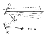
- Figure 4 indicates how the lines of vision (7) and (9) can be twisted from the centre of the first mirror (1) to both sides in a downward direction to the position indicated by (7') en (9').
- This twisting is obtained by twisting the mirror surface of the first mirror.
- the mirror surface of the first mirror is thereby rotated downwardly from the middle to both sides.
- This twisting of the field of vision is effective because, nearer the side of the field of vision, the edge of the car roof restricts the downward vision less.
- the downward twisting from (7) to (7') therefore provides an increased view of the road surface immediately behind and beside the car and thereby a better view of overtaking traffic which is near the car and diagonally behind it.
- the torsion of the mirror surface of the first mirror makes it possible to view a relatively larger part of the sides of the lower section of the rearward field of vision. Consequently, the first mirror can have a relatively lower height (14), whereby the air resistance of the first mirror (1) becomes as low as possible. In view of the importance of a low air resistance, the first mirror is also surrounded by an aero-dynamic hood (16) or a spoiler.
- the image blurr which is a consequence of the twosided torsion of the mirror surface of the first mirror is compensated in the case drawn here by opposed twosided torsion of the mirror surface of the third mirror (3).
- both an optimal field of vision and a relatively low height of the first mirror and a high picture-clarity can be achieved.
- a further improvement of the picture quality is achieved by increasing the degree of torsion (meant as angle rotation per unit of length of the mirror) from the centre of the mirrors to both sides.
- a gradual increase of the degree of torsion from the centre thereby causes the transition from left to right torsion in the centre of the mirrors to take place gradually as well, and does not lead to problematic image deformation in the centre.
- the mirror glass can be moulded into the desired shape when it is hot. It is, however, also possible to twist a flat glass mirror mechanically, for instance, by clamping at least one longitudinal side in a bent setting. In order to obtain a gradually increasing degree of torsion starting from the centre of the mirror, a circularly bent setting is then required on a longitudinal side in combination with a straight or circularly bent setting on the other longitudinal side.
- the intended gradually increasing torsion can also be obtained by bending the glass longitudinally over a cross support wherein a strip has been placed under the glass, the strip having such a section that a circular bendingline is formed on the one longitudinal side while the other longitudinal side is clamped in a straight position.
- the glass can also be clamped or glued onto a strip of metal or another form-retaining material which has previously been moulded into the desired shape.
- the field of vision of the rear view apparatus according to the invention can be further increased by using convexly or cilyndrically curved mirror surfaces.
- the direction of the mirror surface here means the direction of the perpendicular line on the mirror surface.
- a directional tolerance applies of plus and minus 40°.
- the directional indication "inclined” means a directional deviation of 45°.
Landscapes
- Engineering & Computer Science (AREA)
- Mechanical Engineering (AREA)
- Multimedia (AREA)
- Chemical & Material Sciences (AREA)
- Combustion & Propulsion (AREA)
- General Engineering & Computer Science (AREA)
- Rear-View Mirror Devices That Are Mounted On The Exterior Of The Vehicle (AREA)
- Optical Elements Other Than Lenses (AREA)
Claims (17)
- Rücksichtvorrichtung für Fahrzeuge, insbesondere Personenkraftwagen, mit zumindest drei Spiegeln, wovon der erste Spiegel (1) höher wie das Kraftwagendach aufgestellt ist, und der dritte Spiegel (3) in der Fahrerkabine vor dem Kopf des Fahrers aufgestellt ist, wobei der zweite Spiegel zum Lenken des Lichtstrahlenbündels vom ersten Spiegel zum dritten Spiegel aufgestellt ist, dadurch gekennzeichnet, daß der erste (1), der zweite (2) und der dritte (3) Spiegel derart angeordnet sind, daß das Lichtstrahlbündel zwischen den Spiegeln, die innerhalb bzw. außerhalb der Fahrerkabine angeordnet sind, durch das vordere Fenster des Kraftfahrzeugs in die Fahrerkabine hineintritt.
- Rücksichtvorrichtung nach Anspruch 1, dadurch gekennzeichnet, daß der zweite Spiegel (2) oberhalb des ersten Spiegels (1) aufgestellt ist, wobei die Spiegeloberfläche des zweiten Spiegels (2) nach unten gelenkt ist und die Spiegeloberfläche des ersten Spiegels (19) rückwärts und nach oben geneigt ist.
- Rücksichtvorrichtung nach Anspruch 2, dadurch gekennzeichnet, daß die Spiegeloberfläche des ersten Spiegels (1) einen Winkel α von 5-85°, vorzugsweise von ungefähr 60°, mit der horizontalen Ebene bestimmt.
- Rücksichtvorrichtung nach Anspruch 2 oder 3, dadurch gekennzeichnet, daß der erste (1) und der zweite Spiegel in einem Spiegelhalter, wie ein Rahmen oder eine Haube angeordnet sind, wobei die Spiegeloberfläche des zweiten Spiegels (2) an einem ungefähr horizontalen, rückwärts sich erstreckenden, vordachförmigen Teil des Spiegelhalters benachbart angeordnet ist.
- Rücksichtvorrichtung nach Anspruch 1, dadurch gekennzeichnet, daß der zweite Spiegel (2) unterhalb des dritten Spiegels (3) angeordnet ist und mit einer aufwärts neigenden Spiegeloberfläche versehen ist.
- Rücksichtvorrichtung nach einem der vorgehenden Ansprüche, dadurch gekennzeichnet, daß die Längsachse der Spiegel (1, 2, 3) im Verhältnis zu einander parallel sind.
- Rücksichtvorrichtung nach einem der vorgehenden Ansprüche, dadurch gekennzeichnet, daß die Spiegeloberflächen von zumindest zwei Spiegeln (1, 2, 3) in Längsrichtung der Spiegeloberflächen verdreht sind.
- Rücksichtvorrichtung nach Anspruch 7, dadurch gekennzeichnet, daß die Verdrehung der Spiegeloberflächen von der Mitte bis zu den Seiten der Spiegel entgegengesetzt ist.
- Rücksichtvorrichtung nach Anspruch 8, dadurch gekennzeichnet, daß die entgegengesetzte Verdrehung von der Mitte zu den Seiten der Spiegel, vorzugsweise im Verhältnis zu dem Abstand von der Mitte, zunimmt.
- Rücksichtvorrichtung nach Anspruch 9, dadurch gekennzeichnet, daß die Verdrehung eine zusammengesetzte Verdrehung ist und aus einer Verdrehung besteht, die gleichbleibend über die Länge des Spiegels ist, worauf eine Verdrehung, die von der Mitte zu den Seiten entgegengesetzt ist, hinzugefügt ist.
- Rücksichtvorrichtung nach einem der vorgehenden Ansprüche 7-10, dadurch gekennzeichnet, daß die Spiegeloberflächen der Spiegel (1, 2, 3) im Verhältnis zu einander verdreht sind um Bildschleier, der sich aus der Verdrehung ergibt, auszugleichen.
- Rücksichtvorrichtung nach einem der vorgehenden Ansprüche 7-11, dadurch gekennzeichnet, daß die Verdrehung der Spiegeloberflächen durch mechanische Verformung des platten Spiegelglases erhalten wird.
- Rücksichtvorrichtung nach einem der vorgehenden Ansprüche 9-11, dadurch gekennzeichnet, daß ein entgegengesetzter Verdrehungsgrad, der nach und nach ab der Mitte zunimmt, durch das Festklemmen einer oder beiden Längsseiten des Spiegelglases in einer kreisähnlich gebogenen Fassung, oder durch das Befestigen oder Festklemmen gegen einen verdrehten Metallstreifen oder anderes Material erhalten wird.
- Rücksichtvorrichtung nach einem der vorgehenden Ansprüche, dadurch gekennzeichnet, daß zumindest einer der Längsachsen der Spiegel mit einer Linie (11), die mit einem Winkel β von 50° bis 90° mit der Ebene (13), welche das Fahrzeug in der Mitte der Länge nach durchschneidet, bestimmt, parallel ist.
- Rücksichtvorrichtung nach einem der vorgehenden Ansprüche, dadurch gekennzeichnet, daß der erste Spiegel oberhalb des Daches durch Schenkel die am Dach befestigt sind, wie die Schenkel eines Kraftfahrzeuggepäckträgers, befestigt ist.
- Rücksichtvorrichtung nach einem der vorgehenden Ansprüche, dadurch gekennzeichnet, daß eine oder mehrere der Spiegeloberflächen in einer konvexen, konkaven, zylindrischen, sphärischen oder anderen Weise gebogen sind.
- Rücksichtvorrichtung nach einem der vorgehenden Ansprüche, wobei die Spiegeloberfläche zumindest eines der Spiegel (1, 2, 3) aus mehreren, getrennten Oberflächen aufgebaut ist, die zusammen ein angemessen durchgehendes Bild verschaffen.
Applications Claiming Priority (3)
| Application Number | Priority Date | Filing Date | Title |
|---|---|---|---|
| NL9101784A NL9101784A (nl) | 1991-10-24 | 1991-10-24 | Achteruitkijkinrichting. |
| NL9101784 | 1991-10-24 | ||
| PCT/NL1992/000190 WO1993008041A1 (en) | 1991-10-24 | 1992-10-23 | Rear view apparatus |
Publications (2)
| Publication Number | Publication Date |
|---|---|
| EP0608385A1 EP0608385A1 (de) | 1994-08-03 |
| EP0608385B1 true EP0608385B1 (de) | 1995-12-27 |
Family
ID=19859844
Family Applications (1)
| Application Number | Title | Priority Date | Filing Date |
|---|---|---|---|
| EP92924043A Expired - Lifetime EP0608385B1 (de) | 1991-10-24 | 1992-10-23 | Rücksichtvorrichtung |
Country Status (5)
| Country | Link |
|---|---|
| US (1) | US5608581A (de) |
| EP (1) | EP0608385B1 (de) |
| DE (1) | DE69207204T2 (de) |
| NL (1) | NL9101784A (de) |
| WO (1) | WO1993008041A1 (de) |
Cited By (1)
| Publication number | Priority date | Publication date | Assignee | Title |
|---|---|---|---|---|
| DE212012000092U1 (de) | 2011-05-06 | 2013-12-12 | Arkady Veniaminovich Dubrovsky | Spiegelsystem für ein Fahrzeug |
Families Citing this family (3)
| Publication number | Priority date | Publication date | Assignee | Title |
|---|---|---|---|---|
| WO2004015711A2 (en) * | 2002-08-09 | 2004-02-19 | The Governing Council Of The University Of Toronto | Low leakage asymmetric sram cell devices |
| US20040156129A1 (en) * | 2003-02-11 | 2004-08-12 | Diaz Elvis O. | Safety rearview mirror |
| US20050134982A1 (en) * | 2003-12-23 | 2005-06-23 | Bob Stonecypher | Blind spot curved mirror |
Family Cites Families (11)
| Publication number | Priority date | Publication date | Assignee | Title |
|---|---|---|---|---|
| DE2129220A1 (de) * | 1971-06-12 | 1972-12-14 | Volkswagenwerk Ag, 3180 Wolfsburg | Periskopspiegelsystem |
| US3806233A (en) * | 1971-12-23 | 1974-04-23 | Trw Inc | Multiface automobile rear-view mirror system |
| US3774996A (en) * | 1972-08-22 | 1973-11-27 | Donnelly Mirrors Inc | Rearview periscope adjustment means for vehicles |
| DE2408825A1 (de) * | 1973-02-26 | 1974-09-19 | Ichiko Industries Ltd | Periskopartige rueckspiegelanordnung fuer kraftfahrzeuge |
| US3827788A (en) * | 1973-03-30 | 1974-08-06 | Gen Motors Corp | One-way mirror periscope rear vision system |
| GB1534545A (en) * | 1976-05-19 | 1978-12-06 | Anstey N | Rear-view mirror system |
| JPS5551636A (en) * | 1978-10-09 | 1980-04-15 | Katsumata Giken:Kk | Fender mirror for automobile |
| US4490013A (en) * | 1982-04-20 | 1984-12-25 | Milan Pribis | Elongated panoramic mirror deflector |
| DE3408984A1 (de) * | 1984-03-12 | 1985-09-12 | Bernd Dipl.-Ing. 8000 München Scheffel | Rueckspiegeleinrichtung |
| DE8518076U1 (de) * | 1985-06-21 | 1985-09-19 | Bachor, Edith, 6000 Frankfurt | Weitwinkelrückspiegel für Fahrzeuge |
| US4643544A (en) * | 1985-11-21 | 1987-02-17 | Loughran William P | Three view in one mirror |
-
1991
- 1991-10-24 NL NL9101784A patent/NL9101784A/nl not_active Application Discontinuation
-
1992
- 1992-10-23 US US08/211,970 patent/US5608581A/en not_active Expired - Fee Related
- 1992-10-23 EP EP92924043A patent/EP0608385B1/de not_active Expired - Lifetime
- 1992-10-23 DE DE69207204T patent/DE69207204T2/de not_active Expired - Fee Related
- 1992-10-23 WO PCT/NL1992/000190 patent/WO1993008041A1/en not_active Ceased
Cited By (1)
| Publication number | Priority date | Publication date | Assignee | Title |
|---|---|---|---|---|
| DE212012000092U1 (de) | 2011-05-06 | 2013-12-12 | Arkady Veniaminovich Dubrovsky | Spiegelsystem für ein Fahrzeug |
Also Published As
| Publication number | Publication date |
|---|---|
| WO1993008041A1 (en) | 1993-04-29 |
| US5608581A (en) | 1997-03-04 |
| DE69207204D1 (de) | 1996-02-08 |
| EP0608385A1 (de) | 1994-08-03 |
| DE69207204T2 (de) | 1996-08-14 |
| NL9101784A (nl) | 1993-05-17 |
Similar Documents
| Publication | Publication Date | Title |
|---|---|---|
| US5500766A (en) | Blind spot side mirror | |
| US6104552A (en) | Vehicular rearview mirror assembly with forward vision optical system | |
| US5621569A (en) | Rear-view mirror for vehicles | |
| US9487143B2 (en) | Mirror assembly with formed reflective element substrate | |
| US8087791B2 (en) | Methods and systems for adjusting the position of vehicle outside mirrors | |
| US3909117A (en) | Vehicular rear viewing device | |
| EP0279221B1 (de) | Rückblickspiegel | |
| GB2458898A (en) | A head up display system with ghost image elimination means | |
| JP2006231998A (ja) | フロントピラー死角の視認装置 | |
| US7001032B2 (en) | Automotive rear view mirror | |
| US4895435A (en) | Apparatus for improving a driver's rearward field of vision in a motor vehicle | |
| US5608581A (en) | Rear view apparatus | |
| US3774996A (en) | Rearview periscope adjustment means for vehicles | |
| WO1996015921A1 (en) | Rearview mirror system for vehicles | |
| US4277142A (en) | Periscopic mirror | |
| US4435044A (en) | Rear view mirror assembly | |
| US6424474B1 (en) | Optical rear view system | |
| GB2188013A (en) | Rear view mirror | |
| CN119894707A (zh) | 用于机动车的反射显示系统 | |
| US20070030582A1 (en) | Oval elliptical mirror with orientation line | |
| US8488256B2 (en) | Indirect vision system enabling blind spots to be minimized without distorting the formed image | |
| US8899764B2 (en) | Distortion-free image capture mirror which may be used with an automotive side view mirror for capturing an image from an area representing a blind spot for a drive of a vehicle fitted with the distortion-free image capture mirror | |
| US7080911B2 (en) | Combination mirror mount and headlight visor for cross view or spot mirror | |
| EP0560773B1 (de) | Einrichtung zur Minderung von Reflektionen, die eine Anzeigeeinheit eines Kraftfahrzeugs umfasst | |
| US20250155615A1 (en) | Mirror assembly with formed reflective element substrate |
Legal Events
| Date | Code | Title | Description |
|---|---|---|---|
| PUAI | Public reference made under article 153(3) epc to a published international application that has entered the european phase |
Free format text: ORIGINAL CODE: 0009012 |
|
| 17P | Request for examination filed |
Effective date: 19940524 |
|
| AK | Designated contracting states |
Kind code of ref document: A1 Designated state(s): DE FR GB NL |
|
| 17Q | First examination report despatched |
Effective date: 19940927 |
|
| GRAA | (expected) grant |
Free format text: ORIGINAL CODE: 0009210 |
|
| AK | Designated contracting states |
Kind code of ref document: B1 Designated state(s): DE FR GB NL |
|
| REF | Corresponds to: |
Ref document number: 69207204 Country of ref document: DE Date of ref document: 19960208 |
|
| ET | Fr: translation filed | ||
| PLBE | No opposition filed within time limit |
Free format text: ORIGINAL CODE: 0009261 |
|
| STAA | Information on the status of an ep patent application or granted ep patent |
Free format text: STATUS: NO OPPOSITION FILED WITHIN TIME LIMIT |
|
| 26N | No opposition filed | ||
| PGFP | Annual fee paid to national office [announced via postgrant information from national office to epo] |
Ref country code: FR Payment date: 19990928 Year of fee payment: 8 |
|
| PGFP | Annual fee paid to national office [announced via postgrant information from national office to epo] |
Ref country code: GB Payment date: 19991020 Year of fee payment: 8 |
|
| PGFP | Annual fee paid to national office [announced via postgrant information from national office to epo] |
Ref country code: DE Payment date: 19991021 Year of fee payment: 8 |
|
| PGFP | Annual fee paid to national office [announced via postgrant information from national office to epo] |
Ref country code: NL Payment date: 19991029 Year of fee payment: 8 |
|
| PG25 | Lapsed in a contracting state [announced via postgrant information from national office to epo] |
Ref country code: GB Free format text: LAPSE BECAUSE OF NON-PAYMENT OF DUE FEES Effective date: 20001023 |
|
| PG25 | Lapsed in a contracting state [announced via postgrant information from national office to epo] |
Ref country code: NL Free format text: LAPSE BECAUSE OF NON-PAYMENT OF DUE FEES Effective date: 20010501 |
|
| GBPC | Gb: european patent ceased through non-payment of renewal fee |
Effective date: 20001023 |
|
| PG25 | Lapsed in a contracting state [announced via postgrant information from national office to epo] |
Ref country code: FR Free format text: LAPSE BECAUSE OF NON-PAYMENT OF DUE FEES Effective date: 20010629 |
|
| NLV4 | Nl: lapsed or anulled due to non-payment of the annual fee |
Effective date: 20010501 |
|
| PG25 | Lapsed in a contracting state [announced via postgrant information from national office to epo] |
Ref country code: DE Free format text: LAPSE BECAUSE OF NON-PAYMENT OF DUE FEES Effective date: 20010703 |
|
| REG | Reference to a national code |
Ref country code: FR Ref legal event code: ST |