EP0608421A1 - Materiau metallique ayant une excellente resistance aux solutions chimiques et dispositif de traitement par solutions chimiques ou pieces d'un tel dispositif utilisant ce materiau - Google Patents
Materiau metallique ayant une excellente resistance aux solutions chimiques et dispositif de traitement par solutions chimiques ou pieces d'un tel dispositif utilisant ce materiau Download PDFInfo
- Publication number
- EP0608421A1 EP0608421A1 EP92921332A EP92921332A EP0608421A1 EP 0608421 A1 EP0608421 A1 EP 0608421A1 EP 92921332 A EP92921332 A EP 92921332A EP 92921332 A EP92921332 A EP 92921332A EP 0608421 A1 EP0608421 A1 EP 0608421A1
- Authority
- EP
- European Patent Office
- Prior art keywords
- chemical solution
- fluoride
- metallic material
- indicates
- accordance
- Prior art date
- Legal status (The legal status is an assumption and is not a legal conclusion. Google has not performed a legal analysis and makes no representation as to the accuracy of the status listed.)
- Withdrawn
Links
Images




Classifications
-
- F—MECHANICAL ENGINEERING; LIGHTING; HEATING; WEAPONS; BLASTING
- F16—ENGINEERING ELEMENTS AND UNITS; GENERAL MEASURES FOR PRODUCING AND MAINTAINING EFFECTIVE FUNCTIONING OF MACHINES OR INSTALLATIONS; THERMAL INSULATION IN GENERAL
- F16L—PIPES; JOINTS OR FITTINGS FOR PIPES; SUPPORTS FOR PIPES, CABLES OR PROTECTIVE TUBING; MEANS FOR THERMAL INSULATION IN GENERAL
- F16L58/00—Protection of pipes or pipe fittings against corrosion or incrustation
- F16L58/02—Protection of pipes or pipe fittings against corrosion or incrustation by means of internal or external coatings
- F16L58/04—Coatings characterised by the materials used
- F16L58/10—Coatings characterised by the materials used by rubber or plastics
-
- B—PERFORMING OPERATIONS; TRANSPORTING
- B01—PHYSICAL OR CHEMICAL PROCESSES OR APPARATUS IN GENERAL
- B01J—CHEMICAL OR PHYSICAL PROCESSES, e.g. CATALYSIS OR COLLOID CHEMISTRY; THEIR RELEVANT APPARATUS
- B01J19/00—Chemical, physical or physico-chemical processes in general; Their relevant apparatus
- B01J19/02—Apparatus characterised by being constructed of material selected for its chemically-resistant properties
-
- B—PERFORMING OPERATIONS; TRANSPORTING
- B05—SPRAYING OR ATOMISING IN GENERAL; APPLYING FLUENT MATERIALS TO SURFACES, IN GENERAL
- B05D—PROCESSES FOR APPLYING FLUENT MATERIALS TO SURFACES, IN GENERAL
- B05D5/00—Processes for applying liquids or other fluent materials to surfaces to obtain special surface effects, finishes or structures
- B05D5/08—Processes for applying liquids or other fluent materials to surfaces to obtain special surface effects, finishes or structures to obtain an anti-friction or anti-adhesive surface
- B05D5/083—Processes for applying liquids or other fluent materials to surfaces to obtain special surface effects, finishes or structures to obtain an anti-friction or anti-adhesive surface involving the use of fluoropolymers
-
- B—PERFORMING OPERATIONS; TRANSPORTING
- B05—SPRAYING OR ATOMISING IN GENERAL; APPLYING FLUENT MATERIALS TO SURFACES, IN GENERAL
- B05D—PROCESSES FOR APPLYING FLUENT MATERIALS TO SURFACES, IN GENERAL
- B05D7/00—Processes, other than flocking, specially adapted for applying liquids or other fluent materials to particular surfaces or for applying particular liquids or other fluent materials
- B05D7/14—Processes, other than flocking, specially adapted for applying liquids or other fluent materials to particular surfaces or for applying particular liquids or other fluent materials to metal, e.g. car bodies
-
- B—PERFORMING OPERATIONS; TRANSPORTING
- B05—SPRAYING OR ATOMISING IN GENERAL; APPLYING FLUENT MATERIALS TO SURFACES, IN GENERAL
- B05D—PROCESSES FOR APPLYING FLUENT MATERIALS TO SURFACES, IN GENERAL
- B05D7/00—Processes, other than flocking, specially adapted for applying liquids or other fluent materials to particular surfaces or for applying particular liquids or other fluent materials
- B05D7/22—Processes, other than flocking, specially adapted for applying liquids or other fluent materials to particular surfaces or for applying particular liquids or other fluent materials to internal surfaces, e.g. of tubes
-
- C—CHEMISTRY; METALLURGY
- C23—COATING METALLIC MATERIAL; COATING MATERIAL WITH METALLIC MATERIAL; CHEMICAL SURFACE TREATMENT; DIFFUSION TREATMENT OF METALLIC MATERIAL; COATING BY VACUUM EVAPORATION, BY SPUTTERING, BY ION IMPLANTATION OR BY CHEMICAL VAPOUR DEPOSITION, IN GENERAL; INHIBITING CORROSION OF METALLIC MATERIAL OR INCRUSTATION IN GENERAL
- C23C—COATING METALLIC MATERIAL; COATING MATERIAL WITH METALLIC MATERIAL; SURFACE TREATMENT OF METALLIC MATERIAL BY DIFFUSION INTO THE SURFACE, BY CHEMICAL CONVERSION OR SUBSTITUTION; COATING BY VACUUM EVAPORATION, BY SPUTTERING, BY ION IMPLANTATION OR BY CHEMICAL VAPOUR DEPOSITION, IN GENERAL
- C23C8/00—Solid state diffusion of only non-metal elements into metallic material surfaces; Chemical surface treatment of metallic material by reaction of the surface with a reactive gas, leaving reaction products of surface material in the coating, e.g. conversion coatings, passivation of metals
- C23C8/80—After-treatment
-
- B—PERFORMING OPERATIONS; TRANSPORTING
- B01—PHYSICAL OR CHEMICAL PROCESSES OR APPARATUS IN GENERAL
- B01J—CHEMICAL OR PHYSICAL PROCESSES, e.g. CATALYSIS OR COLLOID CHEMISTRY; THEIR RELEVANT APPARATUS
- B01J2219/00—Chemical, physical or physico-chemical processes in general; Their relevant apparatus
- B01J2219/02—Apparatus characterised by their chemically-resistant properties
- B01J2219/0204—Apparatus characterised by their chemically-resistant properties comprising coatings on the surfaces in direct contact with the reactive components
- B01J2219/0236—Metal based
-
- B—PERFORMING OPERATIONS; TRANSPORTING
- B01—PHYSICAL OR CHEMICAL PROCESSES OR APPARATUS IN GENERAL
- B01J—CHEMICAL OR PHYSICAL PROCESSES, e.g. CATALYSIS OR COLLOID CHEMISTRY; THEIR RELEVANT APPARATUS
- B01J2219/00—Chemical, physical or physico-chemical processes in general; Their relevant apparatus
- B01J2219/02—Apparatus characterised by their chemically-resistant properties
- B01J2219/0204—Apparatus characterised by their chemically-resistant properties comprising coatings on the surfaces in direct contact with the reactive components
- B01J2219/0236—Metal based
- B01J2219/024—Metal oxides
-
- B—PERFORMING OPERATIONS; TRANSPORTING
- B01—PHYSICAL OR CHEMICAL PROCESSES OR APPARATUS IN GENERAL
- B01J—CHEMICAL OR PHYSICAL PROCESSES, e.g. CATALYSIS OR COLLOID CHEMISTRY; THEIR RELEVANT APPARATUS
- B01J2219/00—Chemical, physical or physico-chemical processes in general; Their relevant apparatus
- B01J2219/02—Apparatus characterised by their chemically-resistant properties
- B01J2219/025—Apparatus characterised by their chemically-resistant properties characterised by the construction materials of the reactor vessel proper
- B01J2219/0277—Metal based
Definitions
- the present invention relates to a metallic material having superior resistance to chemical solutions, as well as to a chemical solution treating device and parts used in this chemical solution treating device.
- plastic materials possessing resistance to chemical solutions such as PVF, Teflon (the brand name of a polyethylene fluoride system resin produced by E.I. du Pont de Nemours & Co. Inc.), and the like were commonly employed in devices for the supply of ultrapure water or chemical solutions, or devices which conducted treatment, such as washing, or the like, using these.
- metallic materials react violently with HCl, H2SO4, HF, and the like, and are eroded, and thus could not be employed, so that plastic materials which were not eroded in this manner were used.
- plastic materials were beset by problems in that they were softer and more easily damaged than metals.
- the plastic materials could not be worked with the same high degree of precision as metallic materials, so that when plastic materials were used, for example, to produce wafer cassettes or the like, the precision was insufficient, and it was for this reason impossible to use such wafer cassettes in an automatic wafer conveying device.
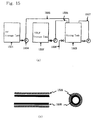
- Fig. 15(a) depicts a typical chemical preparation system in accordance with the conventional technology; for example, this system mixes hydrofluoric acid, HF, and an ammonium fluoride solution, NH4F, and produces buffered hydrofluoric acid.
- reference 1501 indicates, an HF storage tank
- reference 1502 indicates an NH4F storage tank
- reference 1503 indicates a mixing tank
- reference 1504 indicates a pump
- references 1505 and 1507 indicate piping comprising a Teflon tube covered by a metallic tube
- reference 1506 indicates a mixture solution supply piping comprising a tube identical to that indicated by reference 1507.
- a cross-sectional view of this piping is shown in Fig. 15(b).
- Reference 1508 indicates a Teflon tube
- reference 1509 indicates a metallic tube.
- the HF in HF storage tank 1501 and the NH4F in storage tank 1502 are mixed in mixing tank 1503
- the HF in HF storage tank 1501 is pumped up by pump 1504
- the flow rate thereof is controlled by the inner diameter of piping 1505, comprising a double pipe structure in which the Teflon tube is covered by the metallic tube
- the HF is conveyed to mixing tank 1503.
- the NH4F in NH4F storage tank 1502 is pumped up by a pump
- the flow rate thereof is controlled by the inner diameter of the piping 1505, which has a double pipe structure in which the Teflon tube is covered by the metallic tube, and is conveyed to the mixing tank 1503.
- the HF and NH4F conveyed to the mixing tank 1503 are passed through circulation line 1507, which is produced in a manner identical to that of conveyance pump 1504 and conveyance piping 1505, these are circulated, and are thus mixed.
- the metallic piping 1509 covering the Teflon tube 1508 is eroded as a result of the chemical solution vapors passing through the Teflon tube, and the lifetime thereof is thus short.
- the metallic piping and the metallic parts are eroded as a result of the degradation of the Teflon, pinholes, and the like, and as a result of metallic dissolution therefrom, the chemical solution becomes contaminated.
- the mass flow controller for the chemical solution must conduct the control of the flow rate by means of the appropriate alteration of the inner diameter of the piping, and as a result, the accuracy of the control of the flow rate is strikingly poor.
- the production of piping or the like using a metallic material having superior resistance to chemical solutions has been desired; however, as there has been no means for the effective prevention of metallic erosion, this has not been realized.
- the present invention has as an object thereof to provide a metallic material having superior resistance to chemical solutions, capable of composing a chemical solution treating device free of erosion of metallic piping, metallic devices, and metallic parts thereof, as well as capable of controlling the flow rate of the solution with high precision and which is free of chemical solution contamination, and to provide a chemical solution treating device and parts for use in such a chemical solution treating device using these metallic materials.
- the metallic materials in accordance with the present invention are provided with at least a basic member composed of a metallic material, a metal fluoride layer or metal oxide layer comprising a fluoride or oxide of the metallic material and formed on the surface of the basic member, and a fluorocarbon film covering the metal fluoride layer or metal oxide layer.
- the chemical solution treating device or the parts for use in such a chemical solution treating device of the present invention are characterized in that at least those parts which are in contact with chemical solutions comprise the above metallic material.
- fluorocarbon is a compound of fluorine and carbon; for example, it is possible to use a polyethylene fluoride resin such as Teflon or the like.
- the fluorocarbon film is formed by means of thermal decomposition, by supplying a compound of fluorine and carbon such as, for example, CF4, C2F6, C3F8, or the like, to the surface of the basic member and heating this.
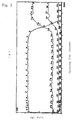
- Fig. 1 shows a first embodiment of the present invention
- Fig. 1(a) is a cross-sectional view of the piping for chemical supply
- Fig. 1(b) is a partially enlarged view of Fig. 1(a).
- Fig. 2 is a diagram showing the production process of the piping.
- Fig. 3(a) is a graph showing the ESCA data after fluoridation processing
- Fig. 3(b) is a graph showing the ESCA data after fluoridation treatment and the application of water.
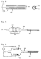
- Fig. 4 is a cross-sectional view of the piping in accordance with an embodiment of the present invention.
- Fig. 5 is a side view of the formation apparatus of the fluorocarbon film.
- Fig. 6 is a side view of the formation apparatus of the fluorocarbon film.
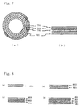
- Fig. 7 is a side view of the piping in accordance with an embodiment of the present invention.
- Fig. 8 shows a production process for the piping shown in Fig. 7.
- Fig. 9 is a type diagram showing the chemical mixing system using the chemical solution device of the present invention.
- Fig. 10 is an angled view of a wafer cassette in accordance with an embodiment of the present invention.
- Fig. 11 is a side view and a partially enlarged view of a beaker in accordance with an embodiment of the present invention.
- Fig. 12 is a side view of a heat exchanger in accordance with an embodiment of the present invention.
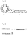
- Fig. 13 is a side view of a piping in accordance with an embodiment of the present invention.
- Fig. 14 is a diagram showing the manufacturing process of the piping shown in Fig. 13.
- Fig. 15 shows a conventional example.
- Reference 101 indicates a tube
- reference 102 indicates a coating having chromium fluoride as a main component thereof
- reference 103 indicates a fluorocarbon film
- reference 202 indicates a coating
- reference 203 indicates a coating having chromium fluoride as a main component thereof
- reference 204 indicates a fluorocarbon film
- reference 401 indicates a tube having chromium fluoride on the inner surface thereof
- reference 402 indicates an electrode
- reference 501 indicates a tube having chromium fluoride on the inner surface thereof
- reference 502 indicates a quartz tube
- reference 503 indicates a coil
- reference 504 indicates CF4 gas
- reference 601 indicates a tube having chromium fluoride on the inner surface thereof
- reference 602 indicates a quartz tube
- reference 603 indicates a plane-parallel electrode
- reference 701 indicates a tube
- reference 702 indicates Ni plating
- reference 703 indicates a coating having nickel fluoride as a main component thereof
- Fig. 1 shows a first embodiment of the present invention
- Fig. 1(a) shows a cross-sectional view of a piping for chemical supply comprising metal
- Fig. 1(b) is an enlarged view of the vicinity of the surface thereof.
- reference 101 indicates a tube having a diameter of 1/2 inches comprising SUS316L.
- Reference 102 indicates a coating having chromium fluoride as a main component thereof, or reference 103 indicates a fluorocarbon film.
- Fig. 2 shows a manufacturing process of the piping shown in Fig. 1.
- coating 202 which has chromium fluoride as a main component thereof, can be accomplished by the fluoridation treatment for a period of 20 minutes and at a temperature of 300 degrees Celsius of the SUS316L shown in Fig. 2(a) with fluorine and gas.
- Reference 202 shown in Fig. 2(b) indicates a fluoride passivating coating.
- the coating 203 shown in Fig. 2(c) which has chromium fluoride as a main component thereof, is formed.
- 2(d) is accomplished by means of the thermal decomposition of, for example, CF4, C2F6, C3F8, or the like. That is to say, the piping is heated to a temperature within a range of 250 - 300 degrees Celsius, and this type of gas is introduced thereinto. When this is done, this gas thermally decomposes, and coating 203, having chromium fluoride as a main component thereof, accumulates on the surface.
- the thickness thereof is on the level of, for example, 5 ⁇ m; however, this thickness can be set to any level in accordance with the desired object.
- Fig. 3 shows the ESCA data in the case in which water was applied to the fluoride film and this was thus converted to a film having chromium fluoride as a main component thereof.
- Fig. 3(a) shows the ESCA data of the SUS316L after fluoridation treatment; this has iron fluoride as main component thereof.
- Fig. 3(b) shows the ESCA data after fluoridation treatment and after the application of water for a period of 5 days; this has chromium fluoride as a main component.
- the sputtering rate in Fig. 3(a) and Fig. 3(b) was 0.1 nm/second, and the thickness of the film having chromium fluoride as a main component thereof was 2000 ⁇ .
- the tube of the present invention was used, for example, as a supply piping for HF, by combining a metal fluoride and Teflon, the resistance to erosion was increased in comparison with the case in which piping comprising only a metal fluoride was used. Furthermore, even if the Teflon is penetrated, or if pinholes are opened in the Teflon, as a result of the resistance to erosion of the metal fluoride, the piping is not eroded, so that there is no danger of metallic contamination from the piping. In addition, piping composed of Teflon is easily damaged, but the present basic members comprise metallic materials, so that they are characteristic in being resistant to damage. That is to say, all problems present in the conventional technology are solved.
- the thickness of the chromium fluoride film was 2000 ⁇ ; however, it is of course the case that a thicker film may be employed.
- the resistance to erosion is sufficient if the thickness is on the level of several ⁇ , and if the thickness is too great, there are problems such as peeling from the metallic basic member and the like.
- a thickness of less than 5000 ⁇ is preferable.
- an electrode 402 is introduced into a tube 401 having a diameter of 1/2 inch and having chromium fluoride on the inner surface thereof, as shown, for example, in Fig. 4, and in the presence of a CF4 gas flow, a high frequency, for example, 13.56 MHz, is applied between the electrode and the 1/2 inch tube, and thereby, a fluorocarbon film is formed.
- a high frequency for example, 13.56 MHz
- a quartz tube 502 and a tube 501 having a diameter of 1/2 inch and having chromium fluoride on the inner surface thereof are placed in contact, a coil 503 is wound around quartz tube 502, and a high frequency, for example, 13.56 MHz, is applied in the presence of a flow of a CF4 gas 504 and an electrodeless discharge is thus conducted, and the fluorocarbon film may also be formed in this manner.
- a high frequency for example, 13.56 MHz
- the fluorocarbon film may also be formed by bringing a quartz tube 602 and a tube 601 having a diameter of 1/2 inch and having chromium fluoride on the inner surface thereof into contact, and applying a high frequency, for example, 13.56 MHz, between the plane parallel electrodes 603 within quartz tube 602.
- Fig. 7(a) shows a cross-sectional view of the piping for chemical supply comprising metal
- Fig. 7(b) shows an expanded view of the vicinity of the surface thereof.
- reference 701 indicates a tube having a diameter of 1/2 inch and comprising, for example, Al or a Al alloy.
- Reference 702 indicates Ni plating
- reference 703 indicates a coating having nickel fluoride as a main component thereof
- reference 704 indicates a fluorocarbon film.
- Fig. 8 shows the manufacturing process of the piping shown in Fig. 7.
- the formation of the coating having nickel fluoride as a main component thereof is accomplished by executing the nickel plating of reference 802 in Fig. 8(b) on the Al or Al alloy shown in Fig. 8(a) and forming the coating having nickel fluoride as a main component thereof indicated by reference 803 in Fig. 8(c) by means of the fluoridation treating thereof. Furthermore, the formation of the fluorocarbon film indicated by reference 804 in Fig. 8(d) is identical to that described in the first embodiment.
- the metal which is plated need not be Al, but may be any metallic material.
- the thickness of the nickel fluoride film and the thickness of the plating may be set to any level in accordance with the desired object.
- the tube of the present invention is employed, for example, as a supply piping for HCl
- the resistance to erosion is increased in comparison to the case in which piping comprising only metal fluoride is employed.
- the Teflon is penetrated or if pinholes are opened in the Teflon, as a result of the resistance to erosion of the metal fluoride, the piping will not be eroded, so that there is absolutely no danger of metallic contamination from the piping.
- piping comprising only Teflon is susceptible to damage; however, as the present piping comprises metal, it is resistant to damage.
- Al is employed, so that lightness is a characteristic feature.
- the technology of the present invention was employed in a conventional chemical mixing system.
- Fig. 9 depicts a chemical mixing system employing the technology of the present invention as a type.
- reference 901 indicates an HF storage tank
- reference 902 indicates an NH4F storage tank
- reference 903 indicates a mixing tank.
- the technology of the present invention is applied to these tanks.
- Reference 904 indicates piping in accordance with the technology of the present invention
- reference 905 indicates a pump in accordance with the technology of the present invention
- reference 906 indicates a mass flow controller in accordance with the technology of the present invention.
- the erosion of the tanks and metallic pipings as a result of the chemical solution penetrating the Teflon, and the contamination of the chemical solution by means of metal dissolving from the metallic parts as a result of metallic erosion, are eliminated, and furthermore, it becomes possible to employ pumps and mass flow controllers comprising metal, so that the accuracy of flow rate control is improved, and the safety is also improved.
- the present invention in place of the tube of the second embodiment, is applied to a wafer casette.
- Fig. 10 shows a wafer case to which the technology of the present invention has been applied.
- Fig. 10(a) shows a wafer case comprising metal
- Fig. 10(b) is an enlarged view of the vicinity of the surface thereof.
- reference 1001 indicates a wafer case base comprising Al or an Al alloy.
- Reference 1002 indicates Ni plating, reference 1003 indicates a coating having nickel fluoride as a main component thereof, while reference 1004 indicates a fluorocarbon film.
- the technology of the present invention was applied to a beaker.
- Fig. 11 a beaker to which the technology of the present invention was applied is shown.
- Fig. 11(a) shows a beaker comprising metal
- Fig. 11(b) is an enlarged view in the vicinity of the surface thereof.
- reference 1101 indicates a beaker base comprising Al or a Al alloy.
- Reference 1102 indicates Ni plating
- reference 1103 indicates a coating having nickel fluoride as a main component thereof
- reference 1104 indicates a fluorocarbon film.
- the beaker comprises metal, so that it is more resistant to damage than beakers comprising glass or Teflon.
- the present beaker comprises metal, and the heat conductivity thereof is good, so that the time required can be shortened.
- the technology of the present invention was applied to a heat exchanger.
- FIG. 12 a cross-sectional view of a heat exchanger to which the technology of the present invention was applied, is shown.
- a source material the temperature of which has been raised as a result of reaction, is introduced at the point marked 1201, and cooled source material exits from the point marked 1204.
- a solvent for heat exchange such as water, Freon, or the like is introduced from the point marked 1202, and exits from the point marked 1203.
- reference 1205 indicates a thin tube having a diameter of approximately 1/4 inch, and by means of employing a plurality of such tubes, the heat exchange capacity is increased.
- the present invention was employed in supply piping for ultrapure water.
- Fig. 13(a) shows a cross-sectional view of piping, comprising metal, for ultrapure water supply, while Fig. 13(b) is an enlarged view in the vicinity of the surface thereof.
- reference 1301 indicates a tube having a diameter of 1/2 inch and comprising, for example, SUS316L.
- Reference 1302 indicates a coating having chromium oxide as a main component thereof, while reference 1303 indicates a fluorocarbon film.
- Fig. 14 shows a manufacturing process of the piping shown in Fig. 10.
- coating 1402 (Fig. 14(b)) having chromium oxide as a main component thereof is conducted by means of the reduction with hydrogen of the SUS316L indicated by reference 1101 in Fig. 14(a).
- the hydrogen concentration may be 100%; however, it is preferable, considering the danger of explosion, to limit the concentration to less than 3%, for example, by dilution with Ar gas. It is of course the case that the gas used for dilution need not be Ar gas. Furthermore, it is possible to increase the thickness of the film by adding oxygen. In this case, as well, considering the danger of explosion, it is preferable to conduct the process at less than 100 ppm.
- the reduction temperature should be greater than 300 degrees Celsius, and preferably 500 degrees Celsius.
- a metallic material possessing superior resistance to chemical solutions which is capable of comprising a chemical solution treating device which does not erode, is capable of accurately controlling flow rate, and which has no chemical solution contamination.
- chemical solution treating devices or parts for chemical solution treating devices which do not erode are capable of accurately controlling flow rate, and have no chemical solution contamination.
Landscapes
- Engineering & Computer Science (AREA)
- Chemical & Material Sciences (AREA)
- Life Sciences & Earth Sciences (AREA)
- Wood Science & Technology (AREA)
- General Engineering & Computer Science (AREA)
- Mechanical Engineering (AREA)
- Organic Chemistry (AREA)
- Chemical Kinetics & Catalysis (AREA)
- Materials Engineering (AREA)
- Metallurgy (AREA)
- Chemical Treatment Of Metals (AREA)
- Laminated Bodies (AREA)
- Other Surface Treatments For Metallic Materials (AREA)
- Preventing Corrosion Or Incrustation Of Metals (AREA)
- Chemically Coating (AREA)
- Cleaning Or Drying Semiconductors (AREA)
Abstract
L'invention se rapporte à un matériau métallique qui possède une excellente résistance aux solutions chimiques et avec lequel on peut former un dispositif de traitement par solutions chimiques exempt d'érosion sur ses parties, pièces et tubulures métalliques, et grâce auquel on peut en outre commander le débit de la solution utilisée avec une précision élevée et sans pollution par la solution chimique. L'invention se rapporte en outre à un dispositif de traitement par solution chimique ou à des parties de ce dispositif qui utilisent de tels matériaux métalliques. Ce matériau se caractérise en ce qu'il comporte au moins un élément de base (101) constitué par un matériau métallique, une couche de fluorure de métal ou une couche d'oxyde (102) formée sur l'élément de base (101) et un film de fluorocarbone (103) destiné à recouvrir la couche de fluorure de métal ou la couche d'oxyde de métal (102).
Applications Claiming Priority (3)
| Application Number | Priority Date | Filing Date | Title |
|---|---|---|---|
| JP295156/91 | 1991-10-15 | ||
| JP3295156A JP3063315B2 (ja) | 1991-10-15 | 1991-10-15 | 耐薬液性に優れた金属材並びにそれを用いた薬液処理装置又は薬液処理装置用部品 |
| PCT/JP1992/001339 WO1993008022A1 (fr) | 1991-10-15 | 1992-10-15 | Materiau metallique ayant une excellente resistance aux solutions chimiques et dispositif de traitement par solutions chimiques ou pieces d'un tel dispositif utilisant ce materiau |
Publications (2)
| Publication Number | Publication Date |
|---|---|
| EP0608421A1 true EP0608421A1 (fr) | 1994-08-03 |
| EP0608421A4 EP0608421A4 (fr) | 1994-12-07 |
Family
ID=17816983
Family Applications (1)
| Application Number | Title | Priority Date | Filing Date |
|---|---|---|---|
| EP19920921332 Withdrawn EP0608421A4 (fr) | 1991-10-15 | 1992-10-15 | Materiau metallique ayant une excellente resistance aux solutions chimiques et dispositif de traitement par solutions chimiques ou pieces d'un tel dispositif utilisant ce materiau. |
Country Status (3)
| Country | Link |
|---|---|
| EP (1) | EP0608421A4 (fr) |
| JP (1) | JP3063315B2 (fr) |
| WO (1) | WO1993008022A1 (fr) |
Cited By (2)
| Publication number | Priority date | Publication date | Assignee | Title |
|---|---|---|---|---|
| WO1996018844A1 (fr) * | 1994-12-17 | 1996-06-20 | Hindle Cockburns Limited | Amelioration pour elements de vannes ou robinets, ou concernant ces elements |
| WO1998007896A1 (fr) * | 1996-08-24 | 1998-02-26 | Basf Coatings Ag | Utilisation d'acides a element halogene pour la fabrication de tuyaux metalliques revetus ou d'aciers revetus a beton arme ou d'armature |
Families Citing this family (1)
| Publication number | Priority date | Publication date | Assignee | Title |
|---|---|---|---|---|
| US6348157B1 (en) | 1997-06-13 | 2002-02-19 | Tadahiro Ohmi | Cleaning method |
Family Cites Families (9)
| Publication number | Priority date | Publication date | Assignee | Title |
|---|---|---|---|---|
| DE3266380D1 (en) * | 1981-06-30 | 1985-10-24 | Suisse Horlogerie Rech Lab | Process for forming a corrosion-resistant coating of a solid lubricant |
| JPH0243625B2 (ja) * | 1983-01-25 | 1990-10-01 | Kuraray Co | Tainetsuseioyobitaiyakuhinseinisuguretafukugobutsu |
| US4756774A (en) * | 1984-09-04 | 1988-07-12 | Fox Steel Treating Co. | Shallow case hardening and corrosion inhibition process |
| DE3534724A1 (de) * | 1985-09-28 | 1987-04-02 | Volkmar Dipl Ing Eigenbrod | Beschichtung fuer metallische oberflaechen und verfahren zum aufbringen der beschichtung |
| JPS62117737A (ja) * | 1985-11-19 | 1987-05-29 | 大日本インキ化学工業株式会社 | 表面被覆アルミニユ−ム材 |
| JPS62132173U (fr) * | 1986-02-12 | 1987-08-20 | ||
| JPH06104221B2 (ja) * | 1986-05-15 | 1994-12-21 | 日本バルカ−工業株式会社 | 金属表面への熱溶融性フツ素樹脂層の形成方法 |
| JPH01180335A (ja) * | 1988-01-12 | 1989-07-18 | Toray Ind Inc | ポリマ被履鉄成形物 |
| DE68918365T2 (de) * | 1988-07-20 | 1995-05-04 | Hashimoto Chemical Ind Co | Metallischer Werkstoff mit durch Fluorierung passiviertem Film und aus dem metallischen Werkstoff bestehende Anlage. |
-
1991
- 1991-10-15 JP JP3295156A patent/JP3063315B2/ja not_active Expired - Lifetime
-
1992
- 1992-10-15 EP EP19920921332 patent/EP0608421A4/fr not_active Withdrawn
- 1992-10-15 WO PCT/JP1992/001339 patent/WO1993008022A1/fr not_active Ceased
Cited By (2)
| Publication number | Priority date | Publication date | Assignee | Title |
|---|---|---|---|---|
| WO1996018844A1 (fr) * | 1994-12-17 | 1996-06-20 | Hindle Cockburns Limited | Amelioration pour elements de vannes ou robinets, ou concernant ces elements |
| WO1998007896A1 (fr) * | 1996-08-24 | 1998-02-26 | Basf Coatings Ag | Utilisation d'acides a element halogene pour la fabrication de tuyaux metalliques revetus ou d'aciers revetus a beton arme ou d'armature |
Also Published As
| Publication number | Publication date |
|---|---|
| WO1993008022A1 (fr) | 1993-04-29 |
| JP3063315B2 (ja) | 2000-07-12 |
| JPH05104672A (ja) | 1993-04-27 |
| EP0608421A4 (fr) | 1994-12-07 |
Similar Documents
| Publication | Publication Date | Title |
|---|---|---|
| US8124240B2 (en) | Protective film structure of metal member, metal component employing protective film structure, and equipment for producing semiconductor or flat-plate display employing protective film structure | |
| EP0794598A1 (fr) | Générateur laser à excimeur, ventilateurs, échangeurs de chaleur pour utiliser avec, et un appareil d'exposition comprenant le-même | |
| US7323231B2 (en) | Apparatus and methods for plasma vapor deposition processes | |
| US6375756B1 (en) | Method for removing a deposited film | |
| US4585696A (en) | Superconducting fiber | |
| Kirlin et al. | MOCVD of BaSrTiO3 for ULSI DRAMs | |
| JP3045576B2 (ja) | ステンレス鋼の不動態膜形成方法及びステンレス鋼 | |
| EP0352061B1 (fr) | Matériau métallique avec film passivé par fluoration et appareil constitué par ce matériau | |
| EP0608421A1 (fr) | Materiau metallique ayant une excellente resistance aux solutions chimiques et dispositif de traitement par solutions chimiques ou pieces d'un tel dispositif utilisant ce materiau | |
| US7234222B1 (en) | Methods and apparatus for optimizing the delivery of a set of gases in a plasma processing system | |
| JP2018107438A (ja) | 金属部材の表面処理方法及び半導体素子の製造方法 | |
| WO1990002212A1 (fr) | Installation d'oxydation de metaux | |
| US6749717B1 (en) | Device for in-situ cleaning of an inductively-coupled plasma chambers | |
| EP1146135B1 (fr) | Acier inoxydable revetu d'un film au fluorure passif et equipement produit au moyen de cet acier | |
| US20220098735A1 (en) | Mixed substantially homogenous coatings deposited by ald | |
| JP3286697B2 (ja) | 溶接部に酸化不動態膜を形成する方法及びプロセス装置 | |
| US5725907A (en) | Metal material formed with fluorocarbon film, process for preparing the material and apparatus made with use of the material | |
| EP0946407B1 (fr) | Procede ameliore de conservation, de transport et de production de fluor actif | |
| KR102489717B1 (ko) | 저 내부식성 금속 기재를 이용한 고순도 불화수소를 저장하기 위한 용기 및 이의 제조방법 | |
| US6436353B1 (en) | Gas recovering apparatus | |
| JPH11165375A (ja) | フッ化不動態膜表面にフッ素樹脂を形成した材料およびその材料を用いた各種装置及び部品 | |
| US6204199B1 (en) | Method for producing a semiconductor device | |
| JPH04161308A (ja) | モールド用簡易金型およびその製造方法 | |
| JPH03215656A (ja) | フッ化不働態膜が形成されたステンレス鋼、その製造方法並びにそのステンレスを用いた装置 | |
| Kitano et al. | High-corrosion-resistant Al2O3 passivation-film formation by selective oxidation on austenitic stainless steel containing Al |
Legal Events
| Date | Code | Title | Description |
|---|---|---|---|
| PUAI | Public reference made under article 153(3) epc to a published international application that has entered the european phase |
Free format text: ORIGINAL CODE: 0009012 |
|
| 17P | Request for examination filed |
Effective date: 19940511 |
|
| AK | Designated contracting states |
Kind code of ref document: A1 Designated state(s): BE DE FR GB IT NL |
|
| A4 | Supplementary search report drawn up and despatched | ||
| AK | Designated contracting states |
Kind code of ref document: A4 Designated state(s): BE DE FR GB IT NL |
|
| STAA | Information on the status of an ep patent application or granted ep patent |
Free format text: STATUS: THE APPLICATION IS DEEMED TO BE WITHDRAWN |
|
| 18D | Application deemed to be withdrawn |
Effective date: 19970501 |