EP0608507A2 - Appareil d'alimentation vibrant pour objets similaires - Google Patents
Appareil d'alimentation vibrant pour objets similaires Download PDFInfo
- Publication number
- EP0608507A2 EP0608507A2 EP93118999A EP93118999A EP0608507A2 EP 0608507 A2 EP0608507 A2 EP 0608507A2 EP 93118999 A EP93118999 A EP 93118999A EP 93118999 A EP93118999 A EP 93118999A EP 0608507 A2 EP0608507 A2 EP 0608507A2
- Authority
- EP
- European Patent Office
- Prior art keywords
- rail
- pot
- ramp
- oscillating
- workpiece
- Prior art date
- Legal status (The legal status is an assumption and is not a legal conclusion. Google has not performed a legal analysis and makes no representation as to the accuracy of the status listed.)
- Granted
Links
Images


Classifications
-
- B—PERFORMING OPERATIONS; TRANSPORTING
- B65—CONVEYING; PACKING; STORING; HANDLING THIN OR FILAMENTARY MATERIAL
- B65G—TRANSPORT OR STORAGE DEVICES, e.g. CONVEYORS FOR LOADING OR TIPPING, SHOP CONVEYOR SYSTEMS OR PNEUMATIC TUBE CONVEYORS
- B65G27/00—Jigging conveyors
- B65G27/34—Jigging conveyors comprising a series of co-operating units
-
- B—PERFORMING OPERATIONS; TRANSPORTING
- B65—CONVEYING; PACKING; STORING; HANDLING THIN OR FILAMENTARY MATERIAL
- B65G—TRANSPORT OR STORAGE DEVICES, e.g. CONVEYORS FOR LOADING OR TIPPING, SHOP CONVEYOR SYSTEMS OR PNEUMATIC TUBE CONVEYORS
- B65G47/00—Article or material-handling devices associated with conveyors; Methods employing such devices
- B65G47/02—Devices for feeding articles or materials to conveyors
- B65G47/04—Devices for feeding articles or materials to conveyors for feeding articles
- B65G47/12—Devices for feeding articles or materials to conveyors for feeding articles from disorderly-arranged article piles or from loose assemblages of articles
- B65G47/14—Devices for feeding articles or materials to conveyors for feeding articles from disorderly-arranged article piles or from loose assemblages of articles arranging or orientating the articles by mechanical or pneumatic means during feeding
- B65G47/1407—Devices for feeding articles or materials to conveyors for feeding articles from disorderly-arranged article piles or from loose assemblages of articles arranging or orientating the articles by mechanical or pneumatic means during feeding the articles being fed from a container, e.g. a bowl
- B65G47/1414—Devices for feeding articles or materials to conveyors for feeding articles from disorderly-arranged article piles or from loose assemblages of articles arranging or orientating the articles by mechanical or pneumatic means during feeding the articles being fed from a container, e.g. a bowl by means of movement of at least the whole wall of the container
- B65G47/1421—Vibratory movement
Definitions
- the invention relates to a vibratory feeder for similar workpieces with a pot coupled to a first vibratory drive for receiving the unordered workpieces, on the wall of which a rising ramp is formed.
- the invention is therefore based on the object of designing the device mentioned at the outset in such a way that the workpieces can not only be provided individually, but also in the same orientation for further processing.
- the ramp ends over a workpiece discharge rail coupled to a second oscillating drive the workpiece discharge rail having a section which extends over the pot base and is provided with deflection baffles. It is thereby achieved that the workpieces, for example screws, are always output in the same orientation from the workpiece delivery rail, and those in the latter are incorrect from the ramp Workpieces that get orientation and are rejected by the chicanes fall back into the pot. It also makes it possible for the identically oriented workpieces to be effectively fed to a further treatment station which is at a distance from the pot.
- the vibratory drives are preferably designed in such a way that the first vibratory drive gives the pot a movement directed in its circumferential direction and the second vibratory drive gives the workpiece delivery rail a movement in its longitudinal direction.
- the vibratory drives expediently work electromagnetically and can each consist of several vibrating segments. It is advantageous if the vibratory drives are attached to a common frame, because then a compact device can be created.
- the straight-line workpiece delivery rail extends through the side wall of the pot, the rail section with the deflection baffles being located within the pot.
- the workpiece discharge rail is preferably designed to be multi-lane, so that several further processing stations can be operated simultaneously by one lane with workpieces of the same orientation.
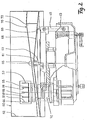
- the vibration feed device for feeding screws or similar workpieces (not shown) rests on a frame, of which only the massive upper frame part 10 is shown schematically.
- the frame part 10 is connected to the other frame parts, which are not shown in detail and are either anchored on the floor 16 at the points indicated by the vertical lines or are free on the floor 16.
- two opposing solid brackets 20, 22 are fastened, each of which carries an electromagnetic oscillating segment 30, 40 on its free end.
- the oscillating segment 30 has an electromagnet 32 which is fastened on the boom 20 via a rubber buffer 34.
- a spring assembly 38 is fastened to the movable armature 36, which in turn is anchored to a screw support 52 which sits on the underside of a workpiece delivery rail 50. Otherwise, the oscillating segment is designed in the same way as that described, for example, in German Patent 28 06 331 is explained.
- the oscillating segment 40 is constructed in the same way as the oscillating segment 30, the spring assembly of the oscillating segment 40 enclosing the same angle to the longitudinal direction of the rail 50 as the spring assembly 38. Both oscillating segments 30 and 40 are synchronized by a control device, not shown and accommodated, for example, in the frame supplied with the required current, so that both oscillating segments 30, 40 form an electromagnetic oscillating drive for the rail 50 and this gives a reciprocating linear movement in the longitudinal direction of the rail 50.
- the rail 50 as shown in FIG. 2, consists of several parallel, equally wide tracks 81, 83, 85, 87, each of which is in the form of a U-shaped channel open at the top with the side walls 51, 53, 56, 57, 59 and the common floor 55.
- the rail 50 passes through a side wall 62 of a vibration pot, designated as a whole by 60, through opposite openings 64, 66, which are cut into the side wall 62 for this purpose.
- the height of the equally high side walls 51, 53 is dimensioned such that, for example, equally oriented screws which are conveyed along the rail 50 in their tracks 81, 83, 85, 87 from right to left as shown in FIGS. 1 and 3, from the Traces cannot fall out sideways.
- the oscillating pot 60 itself is round in plan view, its base 68 rising slightly conically from the outer wall 62 inwards towards the center. In the middle of The bottom of the pot 60 is gripped by a sleeve 61, penetrated by a pin 63 fixed to the frame and secured thereon by means of a union nut 65.
- the bottom 68 of the oscillating pot 60 is fastened on an annular frame 69, on which the upper ends of a plurality of spring assemblies of a plurality of oscillating segments are anchored, of which one spring assembly is designated by 48.
- each of the spring assemblies 48 is fastened to a movable armature each of a swing segment, which is designed as in the aforementioned patent specification 28 06 331 and is similar in construction and mode of operation to the swing segments 30, 40.
- the spring assemblies 48 are equally spaced in the circumferential direction of the round swinging cup 60 and are inclined against the swinging cup 60.
- three spring assemblies 48 are anchored along the circumference of the frame 69, so that the oscillating cup 60 is set in vibration by three oscillating segments synchronously in its circumferential direction.
- the spring assemblies 48 are inclined against the frame 69 lying transversely to the side wall 62 at the same angle in each case.
- the rail 50 penetrates the oscillating pot 60 at a height between the bottom 68 and the upper end of the side wall, so that both the bottom 69 and a ramp to be explained are located below the rail section 54 located within the oscillating pot 60 70 can extend.
- the ramp 70 is formed along an essential circumferential section of the side wall 62 and rises slightly in the circumferential direction of the pot in the representation according to FIG. 3 in the clockwise direction. As shown in FIG. 3, the ramp ends above the rail 50 just behind the opening 64. The ramp points on its top four parallel tracks 71, 73, 75, 77, which are delimited from each other by slight elevations extending in the longitudinal direction of the ramp. The number of tracks 71, 73, 75, 77 is equal to the number of tracks 81, 83, 85, 87 of rail 50, so that one track ends at 76 at one track.
- the ramp 70 has on its peripheral edge remote from the side wall a wall 72 parallel to the side wall 62, which is connected to the floor 68 and extends along the ramp 70.
- the beginning of the ramp 74 goes smoothly, ie without a step into the floor 68.
- baffles attached to the tracks 81, 83, 85, 87 which are adapted to the shape of the workpieces to be conveyed, in this example the screws, and are misoriented Reject screws from the track into the pot.
- These deflection baffles are located on section 54 of the rail 50.
- the device described has the advantage of a very compact design, which nevertheless combines two different vibratory drives. In addition, all rejected, because incorrectly oriented screws fall back into the swing pot 60.
Landscapes
- Engineering & Computer Science (AREA)
- Mechanical Engineering (AREA)
- Jigging Conveyors (AREA)
- Feeding Of Articles To Conveyors (AREA)
- Feeding, Discharge, Calcimining, Fusing, And Gas-Generation Devices (AREA)
Applications Claiming Priority (2)
| Application Number | Priority Date | Filing Date | Title |
|---|---|---|---|
| DE4239683A DE4239683C1 (de) | 1992-11-26 | 1992-11-26 | Schwingzuführgerät für gleichartige Werkstücke |
| DE4239683 | 1992-11-26 |
Publications (3)
| Publication Number | Publication Date |
|---|---|
| EP0608507A2 true EP0608507A2 (fr) | 1994-08-03 |
| EP0608507A3 EP0608507A3 (fr) | 1995-02-22 |
| EP0608507B1 EP0608507B1 (fr) | 1997-05-21 |
Family
ID=6473652
Family Applications (1)
| Application Number | Title | Priority Date | Filing Date |
|---|---|---|---|
| EP93118999A Expired - Lifetime EP0608507B1 (fr) | 1992-11-26 | 1993-11-25 | Appareil d'alimentation vibrant pour objets similaires |
Country Status (3)
| Country | Link |
|---|---|
| EP (1) | EP0608507B1 (fr) |
| AT (1) | ATE153302T1 (fr) |
| DE (2) | DE4239683C1 (fr) |
Cited By (1)
| Publication number | Priority date | Publication date | Assignee | Title |
|---|---|---|---|---|
| CN110203627A (zh) * | 2019-07-20 | 2019-09-06 | 湖南信芯电子技术有限公司 | 吸塑盘排版系统 |
Family Cites Families (6)
| Publication number | Priority date | Publication date | Assignee | Title |
|---|---|---|---|---|
| GB1048827A (en) * | 1962-11-29 | 1966-11-23 | Petro Engineering Services Ltd | Marshalling apparatus for elongate articles |
| FR1429087A (fr) * | 1965-04-02 | 1966-02-18 | Us Industries Inc | Appareil de manipulation d'objets |
| JPS59182120A (ja) * | 1983-03-30 | 1984-10-16 | Shinko Electric Co Ltd | 振動部品供給装置における部品整送装置 |
| JPS61124417A (ja) * | 1984-11-17 | 1986-06-12 | Shinko Electric Co Ltd | 振動部品供給機における部品整送装置 |
| US4739873A (en) * | 1986-11-04 | 1988-04-26 | Tachi-S Co., Ltd. | Tension springs separation device |
| DE8807831U1 (de) * | 1988-06-16 | 1988-08-18 | Kliro-Bau GmbH & Co KG, 51709 Marienheide | Schwingfördergerät |
-
1992
- 1992-11-26 DE DE4239683A patent/DE4239683C1/de not_active Expired - Fee Related
-
1993
- 1993-11-25 EP EP93118999A patent/EP0608507B1/fr not_active Expired - Lifetime
- 1993-11-25 AT AT93118999T patent/ATE153302T1/de not_active IP Right Cessation
- 1993-11-25 DE DE59306521T patent/DE59306521D1/de not_active Expired - Lifetime
Cited By (1)
| Publication number | Priority date | Publication date | Assignee | Title |
|---|---|---|---|---|
| CN110203627A (zh) * | 2019-07-20 | 2019-09-06 | 湖南信芯电子技术有限公司 | 吸塑盘排版系统 |
Also Published As
| Publication number | Publication date |
|---|---|
| EP0608507B1 (fr) | 1997-05-21 |
| EP0608507A3 (fr) | 1995-02-22 |
| DE59306521D1 (de) | 1997-06-26 |
| DE4239683C1 (de) | 1994-05-05 |
| ATE153302T1 (de) | 1997-06-15 |
Similar Documents
| Publication | Publication Date | Title |
|---|---|---|
| EP0311639B1 (fr) | Scie circulaire a coupe transversale pour couper des planches a longueur | |
| DE2212515C3 (de) | Vorrichtung zum Sortieren von körnigen Gegenständen | |
| WO1987004412A1 (fr) | Transporteur de pieces a usiner | |
| AT390577B (de) | Vorrichtung zum zufuehren der querdraehte zur schweisslinie einer gitterschweissmaschine | |
| DE2146646A1 (de) | Vibrierende Schussel zum Zuführen von Knöpfen | |
| EP0608507B1 (fr) | Appareil d'alimentation vibrant pour objets similaires | |
| EP1700643A2 (fr) | Dispositif d'alimentation de récipients | |
| DE2720275A1 (de) | Maschine zur behandlung von behaeltern und insbesondere glasflaschen, die auf einem foerderband kontinuierlich durchlaufen | |
| DE102012111267A1 (de) | Förderkanal einer Schwingfördereinrichtung | |
| EP0193878A2 (fr) | Appareil pour transformer un courant large de bouteilles en un courant de sortie à file unique | |
| DE9417837U1 (de) | Vorrichtung zum Verfahren eines Körpers | |
| DE69411112T2 (de) | Ausrichten von länglichen Gegenständen | |
| WO2021228580A1 (fr) | Appareil et procédé pour diriger et guider des poissons | |
| DE3519481C2 (fr) | ||
| EP0610560B1 (fr) | Appareil pour la manutention des morceaux de pâte | |
| AT390043B (de) | Vibrationsfoerdereinrichtung fuer montageteile | |
| EP0162188A1 (fr) | Dispositif de contrôle pour tiges pouvant rouler | |
| DE3323784C2 (fr) | ||
| DE1507704C3 (de) | Vorrichtung zum Sortieren von Früchten | |
| DE3446763C2 (de) | Vorrichtung zum Vibrationsgleitschleifen von ringförmigen Werkstücken | |
| DE29902259U1 (de) | Vorrichtung zum Sortieren von Endkappen für Rolladenstäbe | |
| DE3224232A1 (de) | Vorrichtung zum handhaben von dosen und aehnlichen behaeltern | |
| DE948323C (de) | Maschine zur Herstellung von Buersten | |
| DE2810467A1 (de) | Vorrichtung zum beschneiden von anschlussleitungen elektrischer bauteile | |
| DE10005019A1 (de) | Vorrichtung zum Weiterbewegen von Gegenständen |
Legal Events
| Date | Code | Title | Description |
|---|---|---|---|
| PUAI | Public reference made under article 153(3) epc to a published international application that has entered the european phase |
Free format text: ORIGINAL CODE: 0009012 |
|
| AK | Designated contracting states |
Kind code of ref document: A2 Designated state(s): AT BE CH DE DK ES FR GB IT LI LU NL SE |
|
| PUAL | Search report despatched |
Free format text: ORIGINAL CODE: 0009013 |
|
| AK | Designated contracting states |
Kind code of ref document: A3 Designated state(s): AT BE CH DE DK ES FR GB IT LI LU NL SE |
|
| 17P | Request for examination filed |
Effective date: 19950324 |
|
| 17Q | First examination report despatched |
Effective date: 19960226 |
|
| GRAG | Despatch of communication of intention to grant |
Free format text: ORIGINAL CODE: EPIDOS AGRA |
|
| GRAH | Despatch of communication of intention to grant a patent |
Free format text: ORIGINAL CODE: EPIDOS IGRA |
|
| GRAH | Despatch of communication of intention to grant a patent |
Free format text: ORIGINAL CODE: EPIDOS IGRA |
|
| GRAA | (expected) grant |
Free format text: ORIGINAL CODE: 0009210 |
|
| AK | Designated contracting states |
Kind code of ref document: B1 Designated state(s): AT BE CH DE DK ES FR GB IT LI LU NL SE |
|
| PG25 | Lapsed in a contracting state [announced via postgrant information from national office to epo] |
Ref country code: NL Free format text: LAPSE BECAUSE OF FAILURE TO SUBMIT A TRANSLATION OF THE DESCRIPTION OR TO PAY THE FEE WITHIN THE PRESCRIBED TIME-LIMIT Effective date: 19970521 Ref country code: IT Free format text: LAPSE BECAUSE OF FAILURE TO SUBMIT A TRANSLATION OF THE DESCRIPTION OR TO PAY THE FEE WITHIN THE PRE;WARNING: LAPSES OF ITALIAN PATENTS WITH EFFECTIVE DATE BEFORE 2007 MAY HAVE OCCURRED AT ANY TIME BEFORE 2007. THE CORRECT EFFECTIVE DATE MAY BE DIFFERENT FROM THE ONE RECORDED.SCRIBED TIME-LIMIT Effective date: 19970521 Ref country code: GB Effective date: 19970521 Ref country code: FR Effective date: 19970521 Ref country code: ES Free format text: THE PATENT HAS BEEN ANNULLED BY A DECISION OF A NATIONAL AUTHORITY Effective date: 19970521 Ref country code: DK Effective date: 19970521 |
|
| REF | Corresponds to: |
Ref document number: 153302 Country of ref document: AT Date of ref document: 19970615 Kind code of ref document: T |
|
| REG | Reference to a national code |
Ref country code: CH Ref legal event code: EP |
|
| REF | Corresponds to: |
Ref document number: 59306521 Country of ref document: DE Date of ref document: 19970626 |
|
| PG25 | Lapsed in a contracting state [announced via postgrant information from national office to epo] |
Ref country code: SE Effective date: 19970821 |
|
| EN | Fr: translation not filed | ||
| NLV1 | Nl: lapsed or annulled due to failure to fulfill the requirements of art. 29p and 29m of the patents act | ||
| GBV | Gb: ep patent (uk) treated as always having been void in accordance with gb section 77(7)/1977 [no translation filed] |
Effective date: 19970521 |
|
| PG25 | Lapsed in a contracting state [announced via postgrant information from national office to epo] |
Ref country code: LU Free format text: LAPSE BECAUSE OF NON-PAYMENT OF DUE FEES Effective date: 19971125 Ref country code: AT Free format text: LAPSE BECAUSE OF NON-PAYMENT OF DUE FEES Effective date: 19971125 |
|
| PG25 | Lapsed in a contracting state [announced via postgrant information from national office to epo] |
Ref country code: LI Free format text: LAPSE BECAUSE OF NON-PAYMENT OF DUE FEES Effective date: 19971130 Ref country code: CH Free format text: LAPSE BECAUSE OF NON-PAYMENT OF DUE FEES Effective date: 19971130 Ref country code: BE Free format text: LAPSE BECAUSE OF NON-PAYMENT OF DUE FEES Effective date: 19971130 |
|
| PLBE | No opposition filed within time limit |
Free format text: ORIGINAL CODE: 0009261 |
|
| STAA | Information on the status of an ep patent application or granted ep patent |
Free format text: STATUS: NO OPPOSITION FILED WITHIN TIME LIMIT |
|
| 26N | No opposition filed | ||
| BERE | Be: lapsed |
Owner name: FELDPAUSCH G.M.B.H. & CO. K.G. Effective date: 19971130 |
|
| REG | Reference to a national code |
Ref country code: CH Ref legal event code: PL |
|
| PGFP | Annual fee paid to national office [announced via postgrant information from national office to epo] |
Ref country code: DE Payment date: 19990528 Year of fee payment: 6 |
|
| PG25 | Lapsed in a contracting state [announced via postgrant information from national office to epo] |
Ref country code: DE Free format text: LAPSE BECAUSE OF THE APPLICANT RENOUNCES Effective date: 20000517 |