EP0608527B1 - Dispositif de fermeture pour réservoir de carburant d'un véhicule automobile - Google Patents
Dispositif de fermeture pour réservoir de carburant d'un véhicule automobile Download PDFInfo
- Publication number
- EP0608527B1 EP0608527B1 EP93119931A EP93119931A EP0608527B1 EP 0608527 B1 EP0608527 B1 EP 0608527B1 EP 93119931 A EP93119931 A EP 93119931A EP 93119931 A EP93119931 A EP 93119931A EP 0608527 B1 EP0608527 B1 EP 0608527B1
- Authority
- EP
- European Patent Office
- Prior art keywords
- tank
- filler pipe
- unit
- closure system
- axis
- Prior art date
- Legal status (The legal status is an assumption and is not a legal conclusion. Google has not performed a legal analysis and makes no representation as to the accuracy of the status listed.)
- Expired - Lifetime
Links
- 239000002828 fuel tank Substances 0.000 title claims description 5
- 239000000945 filler Substances 0.000 claims description 45
- 238000000034 method Methods 0.000 claims description 11
- 238000006073 displacement reaction Methods 0.000 claims 1
- 238000005429 filling process Methods 0.000 claims 1
- 239000000446 fuel Substances 0.000 description 12
- 238000010276 construction Methods 0.000 description 1
- 238000001514 detection method Methods 0.000 description 1
- 230000010354 integration Effects 0.000 description 1
- 230000003287 optical effect Effects 0.000 description 1
- 238000007789 sealing Methods 0.000 description 1
Images

Classifications
-
- B—PERFORMING OPERATIONS; TRANSPORTING
- B60—VEHICLES IN GENERAL
- B60K—ARRANGEMENT OR MOUNTING OF PROPULSION UNITS OR OF TRANSMISSIONS IN VEHICLES; ARRANGEMENT OR MOUNTING OF PLURAL DIVERSE PRIME-MOVERS IN VEHICLES; AUXILIARY DRIVES FOR VEHICLES; INSTRUMENTATION OR DASHBOARDS FOR VEHICLES; ARRANGEMENTS IN CONNECTION WITH COOLING, AIR INTAKE, GAS EXHAUST OR FUEL SUPPLY OF PROPULSION UNITS IN VEHICLES
- B60K15/00—Arrangement in connection with fuel supply of combustion engines or other fuel consuming energy converters, e.g. fuel cells; Mounting or construction of fuel tanks
- B60K15/03—Fuel tanks
- B60K15/04—Tank inlets
- B60K15/05—Inlet covers
-
- E—FIXED CONSTRUCTIONS
- E05—LOCKS; KEYS; WINDOW OR DOOR FITTINGS; SAFES
- E05B—LOCKS; ACCESSORIES THEREFOR; HANDCUFFS
- E05B83/00—Vehicle locks specially adapted for particular types of wing or vehicle
- E05B83/28—Locks for glove compartments, console boxes, fuel inlet covers or the like
- E05B83/34—Locks for glove compartments, console boxes, fuel inlet covers or the like for fuel inlet covers essentially flush with the vehicle surface
-
- E—FIXED CONSTRUCTIONS
- E05—LOCKS; KEYS; WINDOW OR DOOR FITTINGS; SAFES
- E05D—HINGES OR SUSPENSION DEVICES FOR DOORS, WINDOWS OR WINGS
- E05D15/00—Suspension arrangements for wings
- E05D15/40—Suspension arrangements for wings supported on arms movable in vertical planes
- E05D15/42—Suspension arrangements for wings supported on arms movable in vertical planes with pivoted arms and horizontally-sliding guides
-
- E—FIXED CONSTRUCTIONS
- E05—LOCKS; KEYS; WINDOW OR DOOR FITTINGS; SAFES
- E05F—DEVICES FOR MOVING WINGS INTO OPEN OR CLOSED POSITION; CHECKS FOR WINGS; WING FITTINGS NOT OTHERWISE PROVIDED FOR, CONCERNED WITH THE FUNCTIONING OF THE WING
- E05F15/00—Power-operated mechanisms for wings
- E05F15/60—Power-operated mechanisms for wings using electrical actuators
- E05F15/603—Power-operated mechanisms for wings using electrical actuators using rotary electromotors
- E05F15/611—Power-operated mechanisms for wings using electrical actuators using rotary electromotors for swinging wings
- E05F15/63—Power-operated mechanisms for wings using electrical actuators using rotary electromotors for swinging wings operated by swinging arms
-
- E—FIXED CONSTRUCTIONS
- E05—LOCKS; KEYS; WINDOW OR DOOR FITTINGS; SAFES
- E05F—DEVICES FOR MOVING WINGS INTO OPEN OR CLOSED POSITION; CHECKS FOR WINGS; WING FITTINGS NOT OTHERWISE PROVIDED FOR, CONCERNED WITH THE FUNCTIONING OF THE WING
- E05F15/00—Power-operated mechanisms for wings
- E05F15/60—Power-operated mechanisms for wings using electrical actuators
- E05F15/603—Power-operated mechanisms for wings using electrical actuators using rotary electromotors
- E05F15/632—Power-operated mechanisms for wings using electrical actuators using rotary electromotors for horizontally-sliding wings
- E05F15/635—Power-operated mechanisms for wings using electrical actuators using rotary electromotors for horizontally-sliding wings operated by push-pull mechanisms, e.g. flexible or rigid rack-and-pinion arrangements
- E05F15/638—Power-operated mechanisms for wings using electrical actuators using rotary electromotors for horizontally-sliding wings operated by push-pull mechanisms, e.g. flexible or rigid rack-and-pinion arrangements allowing or involving a secondary movement of the wing, e.g. rotational or transversal
-
- B—PERFORMING OPERATIONS; TRANSPORTING
- B60—VEHICLES IN GENERAL
- B60K—ARRANGEMENT OR MOUNTING OF PROPULSION UNITS OR OF TRANSMISSIONS IN VEHICLES; ARRANGEMENT OR MOUNTING OF PLURAL DIVERSE PRIME-MOVERS IN VEHICLES; AUXILIARY DRIVES FOR VEHICLES; INSTRUMENTATION OR DASHBOARDS FOR VEHICLES; ARRANGEMENTS IN CONNECTION WITH COOLING, AIR INTAKE, GAS EXHAUST OR FUEL SUPPLY OF PROPULSION UNITS IN VEHICLES
- B60K15/00—Arrangement in connection with fuel supply of combustion engines or other fuel consuming energy converters, e.g. fuel cells; Mounting or construction of fuel tanks
- B60K15/03—Fuel tanks
- B60K15/04—Tank inlets
- B60K15/0406—Filler caps for fuel tanks
- B60K2015/0419—Self-sealing closure caps, e.g. that don't have to be removed manually
-
- B—PERFORMING OPERATIONS; TRANSPORTING
- B60—VEHICLES IN GENERAL
- B60K—ARRANGEMENT OR MOUNTING OF PROPULSION UNITS OR OF TRANSMISSIONS IN VEHICLES; ARRANGEMENT OR MOUNTING OF PLURAL DIVERSE PRIME-MOVERS IN VEHICLES; AUXILIARY DRIVES FOR VEHICLES; INSTRUMENTATION OR DASHBOARDS FOR VEHICLES; ARRANGEMENTS IN CONNECTION WITH COOLING, AIR INTAKE, GAS EXHAUST OR FUEL SUPPLY OF PROPULSION UNITS IN VEHICLES
- B60K15/00—Arrangement in connection with fuel supply of combustion engines or other fuel consuming energy converters, e.g. fuel cells; Mounting or construction of fuel tanks
- B60K15/03—Fuel tanks
- B60K15/04—Tank inlets
- B60K15/0406—Filler caps for fuel tanks
- B60K2015/0432—Filler caps for fuel tanks having a specific connection between the cap and the vehicle or tank opening
- B60K2015/0445—Filler caps for fuel tanks having a specific connection between the cap and the vehicle or tank opening using hinges
-
- E—FIXED CONSTRUCTIONS
- E05—LOCKS; KEYS; WINDOW OR DOOR FITTINGS; SAFES
- E05Y—INDEXING SCHEME ASSOCIATED WITH SUBCLASSES E05D AND E05F, RELATING TO CONSTRUCTION ELEMENTS, ELECTRIC CONTROL, POWER SUPPLY, POWER SIGNAL OR TRANSMISSION, USER INTERFACES, MOUNTING OR COUPLING, DETAILS, ACCESSORIES, AUXILIARY OPERATIONS NOT OTHERWISE PROVIDED FOR, APPLICATION THEREOF
- E05Y2201/00—Constructional elements; Accessories therefor
- E05Y2201/20—Brakes; Disengaging means; Holders; Stops; Valves; Accessories therefor
- E05Y2201/218—Holders
- E05Y2201/22—Locks
-
- E—FIXED CONSTRUCTIONS
- E05—LOCKS; KEYS; WINDOW OR DOOR FITTINGS; SAFES
- E05Y—INDEXING SCHEME ASSOCIATED WITH SUBCLASSES E05D AND E05F, RELATING TO CONSTRUCTION ELEMENTS, ELECTRIC CONTROL, POWER SUPPLY, POWER SIGNAL OR TRANSMISSION, USER INTERFACES, MOUNTING OR COUPLING, DETAILS, ACCESSORIES, AUXILIARY OPERATIONS NOT OTHERWISE PROVIDED FOR, APPLICATION THEREOF
- E05Y2201/00—Constructional elements; Accessories therefor
- E05Y2201/40—Motors; Magnets; Springs; Weights; Accessories therefor
- E05Y2201/43—Motors
- E05Y2201/434—Electromotors; Details thereof
-
- E—FIXED CONSTRUCTIONS
- E05—LOCKS; KEYS; WINDOW OR DOOR FITTINGS; SAFES
- E05Y—INDEXING SCHEME ASSOCIATED WITH SUBCLASSES E05D AND E05F, RELATING TO CONSTRUCTION ELEMENTS, ELECTRIC CONTROL, POWER SUPPLY, POWER SIGNAL OR TRANSMISSION, USER INTERFACES, MOUNTING OR COUPLING, DETAILS, ACCESSORIES, AUXILIARY OPERATIONS NOT OTHERWISE PROVIDED FOR, APPLICATION THEREOF
- E05Y2900/00—Application of doors, windows, wings or fittings thereof
- E05Y2900/50—Application of doors, windows, wings or fittings thereof for vehicles
- E05Y2900/53—Type of wing
- E05Y2900/534—Fuel lids, charger lids
-
- Y—GENERAL TAGGING OF NEW TECHNOLOGICAL DEVELOPMENTS; GENERAL TAGGING OF CROSS-SECTIONAL TECHNOLOGIES SPANNING OVER SEVERAL SECTIONS OF THE IPC; TECHNICAL SUBJECTS COVERED BY FORMER USPC CROSS-REFERENCE ART COLLECTIONS [XRACs] AND DIGESTS
- Y10—TECHNICAL SUBJECTS COVERED BY FORMER USPC
- Y10T—TECHNICAL SUBJECTS COVERED BY FORMER US CLASSIFICATION
- Y10T292/00—Closure fasteners
- Y10T292/08—Bolts
- Y10T292/096—Sliding
- Y10T292/1014—Operating means
- Y10T292/1021—Motor
-
- Y—GENERAL TAGGING OF NEW TECHNOLOGICAL DEVELOPMENTS; GENERAL TAGGING OF CROSS-SECTIONAL TECHNOLOGIES SPANNING OVER SEVERAL SECTIONS OF THE IPC; TECHNICAL SUBJECTS COVERED BY FORMER USPC CROSS-REFERENCE ART COLLECTIONS [XRACs] AND DIGESTS
- Y10—TECHNICAL SUBJECTS COVERED BY FORMER USPC
- Y10T—TECHNICAL SUBJECTS COVERED BY FORMER US CLASSIFICATION
- Y10T292/00—Closure fasteners
- Y10T292/08—Bolts
- Y10T292/1043—Swinging
- Y10T292/1075—Operating means
- Y10T292/1082—Motor
-
- Y—GENERAL TAGGING OF NEW TECHNOLOGICAL DEVELOPMENTS; GENERAL TAGGING OF CROSS-SECTIONAL TECHNOLOGIES SPANNING OVER SEVERAL SECTIONS OF THE IPC; TECHNICAL SUBJECTS COVERED BY FORMER USPC CROSS-REFERENCE ART COLLECTIONS [XRACs] AND DIGESTS
- Y10—TECHNICAL SUBJECTS COVERED BY FORMER USPC
- Y10T—TECHNICAL SUBJECTS COVERED BY FORMER US CLASSIFICATION
- Y10T292/00—Closure fasteners
- Y10T292/306—Gear
- Y10T292/308—Swinging catch
-
- Y—GENERAL TAGGING OF NEW TECHNOLOGICAL DEVELOPMENTS; GENERAL TAGGING OF CROSS-SECTIONAL TECHNOLOGIES SPANNING OVER SEVERAL SECTIONS OF THE IPC; TECHNICAL SUBJECTS COVERED BY FORMER USPC CROSS-REFERENCE ART COLLECTIONS [XRACs] AND DIGESTS
- Y10—TECHNICAL SUBJECTS COVERED BY FORMER USPC
- Y10T—TECHNICAL SUBJECTS COVERED BY FORMER US CLASSIFICATION
- Y10T70/00—Locks
- Y10T70/50—Special application
- Y10T70/5093—For closures
- Y10T70/554—Cover, lid, cap, encasing shield
Definitions
- the invention relates to a tank closure system for a fuel tank of a motor vehicle according to the preamble of patent claim 1.
- a tank closure system in which a fuel cap which can be screwed on and off on a filler neck by means of an electric drive forms a structural unit together with the drive and a fuel filler flap which is embedded in the side wall of the body.
- a fuel filler cap or the fuel filler flap can be actuated by a motor, so that the driver must always operate one of the parts manually when refueling.
- the present invention has for its object to provide a tank closure system with high ease of use and a simultaneous theft-proof locking.
- the unit is pivotably mounted on an axis of rotation fixed to the body.
- the unit is opened in a manner similar to that previously used for a tank flap.
- the operating mechanism of such a tank closure system is particularly simple.
- the unit is pivotably mounted on a movable carriage.
- the outside tank flap is first lifted slightly from the filler neck during the opening process and then moved completely over the filler neck.
- the carriage moves in a plane perpendicular to the axis of the filler neck.
- An embodiment of the unit in the form of a lever with a two-sided cross section is advantageous, with an actuating bolt being arranged at one end of the lever and a locking bolt at the other end of the lever, starting from the pivot point fixed to the body.
- the associated mechanics can then consist of a locking linkage which can be displaced essentially perpendicular to the axis of the filler neck, which engages with the fork with a fork-shaped slot and which also has a catch hook which engages around the locking bolt when the unit is closed.
- This embodiment is simple and inexpensive in its construction and, due to the few moving parts, is very robust to handle.
- the catch hook has a ramp which is slightly inclined with respect to the actuating direction of the locking rod linkage and which exerts an increasing pressure on the locking bolt during the closing process.
- a sensor which is placed near the filler neck in the open state and which, after detection of the completion of a refueling process, emits an actuating pulse for closing the unit with a time delay to the drive motor.
- an optical sensor can be used as the sensor, which responds to the removal of the nozzle.
- Fig. 1 denotes the vehicle side wall of a motor vehicle, which is otherwise not shown in detail. As usual, this has a recess in which a filler neck 2 of an otherwise not shown fuel tank opens.
- the cutout in the vehicle side wall 1 is covered by a unit, denoted overall by 3, consisting of an external fuel filler flap 4 and a closure part 5 directly connected to it.
- the fuel filler flap 4 In the closed state, the fuel filler flap 4 is in a flush position with the vehicle side wall 1 and the closure part 5 seals off the filler neck 2.
- the closure part 5 assumes the function of a conventional fuel cap.
- the unit 3 has on its inside on both sides of the closure part 5 two unspecified tongue-like projections, on the one of which the unit 3 is pivotably articulated by means of an axis of rotation 7 on a hinge 6 fixed to the body. At the end of the same tongue-like projection, an actuating bolt 8 is arranged.
- the other tongue-like projection carries a locking bolt 9 at its end.
- the bolt linkage consists of two overlapping parts 11a and 11b which can be coupled to one another by means of a bolt block 12 which can be moved perpendicular to the plane of the drawing.
- the drive part 11a of the bolt linkage on the left in FIG. 1 can be displaced along the guides 10 in a plane perpendicular to the axis of the filler neck 2.
- the drive part 11a has a slot 14 running perpendicular to its direction of actuation, which engages around the actuating bolt 8 and takes it with it when the drive part 11a is displaced.
- the length of the slot 14 is chosen so that the movement in the direction of the axis of the filler neck 2 due to the pivoting of the actuating bolt 8 about the axis of rotation 7 can be compensated.
- the bolt part 11b on the right in the drawing of the bolt linkage 11 is connected to a mechanism actuated by the drive motor (not shown), such as a pressure-resistant cable known from sliding roofs, and can likewise be moved along the guides 10 by means of this. It has a catch hook 13 at its end which, in the closed state, engages around and holds the locking bolt 9 on the unit 3.
- the preferably spring-loaded locking block couples the two parts 11a and 11b of the locking linkage 11 with each other and thus also takes the drive part 11a in the direction of arrow A.
- the slot 14 on the drive part 11a guides the actuating pin 8 in a circular arc around the axis of rotation 7 to the right, as a result of which the unit 3 rotates outwards overall about the axis of rotation 7 into the position shown in FIG. 2.
- the swivel angle is more than 90 °, so that the filler neck 2 now released by the unit 3 can be reached unhindered by a fuel nozzle.
- both parts 11a and 11b of the bolt linkage 11 are moved to the left in the direction of an arrow labeled Z in FIG. 1.
- the locking block 12 is disengaged by running onto a ramp, not shown, and then the locking part 11b is moved further to the left independently of the drive part 11a.
- an increasing contact pressure is exerted on the locking bolt 9 during a further movement of the locking part 11b in the direction of the arrow Z. This ensures a secure sealing of the closure part 5 on the filler neck 2.
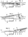
- a vehicle side wall is designated by 21 and a filler neck of a fuel tank (not designated in more detail) by 22.
- a unit 23 formed from a closure part 25 and an external tank flap 24 is pivotally mounted on one side by means of an axis of rotation 27 on a slide 26, which along a guide 30 arranged above and below the filler neck 22 in a substantially perpendicular to the axis of the Filler neck 22 lying level is movable.
- the other end of the pivot lever 28 is pivoted on the inside of the unit 23 by means of an axis of rotation 31.
- the pivot lever 28 also has a slide track 32.
- a sliding block 33 is displaceably guided in this slide track 32 and is rotatably mounted on an actuation slide 36 via a driver 34 through an axis of rotation 35.
- the actuation slide 36 can likewise be moved along the guide 30 and for this purpose is also driven by a drive cable or drive linkage, not shown, by a drive line, also not shown Drive motor operated.
- the unit 23 is opened as follows.
- the actuating slide 36 is conveyed by means of the drive motor along the guide 30 in the direction of arrow A, that is to say to the right in the drawing.
- the sliding block 33 articulated via the driver 34 on the actuating slide 36 ensures that the pivoting lever 28 according to FIG. 4 is set up under a sliding movement in the slide track 32.
- the slide 26 carrying the axis of rotation 27 remains in its position shown in FIG. 4.
- the pivot lever 28 begins to turn to the right and exerts a tensile force on the slide 26.
- the pivot lever 28 is completely turned over into the position shown in FIG. 5, the carriage 26 has moved completely past the filler neck 22 to the right, so that the unit 23 completely clears the filler neck 22.
- the steps described above are carried out in reverse order during the closing process.
- the actuation slide 36 moves to the left in the drawing and causes the pivoting lever 28 to pivot back via the sliding block 33.
- the pivoting lever 28 folds to the left and pulls the unit 23 into the position shown in FIG 3 Close position shown.
- the slide track 32 has a track which is slightly inclined with respect to the direction of movement of the guide 30 in the area 32a last passed through by the sliding block 33 when the closing position is approached.
- the sliding block 33 presses the closure part 25 of the unit 23 firmly and tightly against the filler neck 22.
- a unit according to the invention comprising a tank flap and a tank cap is also possible.
- Unlocking takes place, for example, from the interior via a Bowden cable, and is closed by simply pressing the fuel filler flap, whereby a compressible one
- the seal on the closure part seals against the filler neck and a locking mechanism engages via two oppositely inclined inclined ramps (as in DE 39 28 580 C2).
Landscapes
- Engineering & Computer Science (AREA)
- Mechanical Engineering (AREA)
- Life Sciences & Earth Sciences (AREA)
- Sustainable Development (AREA)
- Sustainable Energy (AREA)
- Chemical & Material Sciences (AREA)
- Combustion & Propulsion (AREA)
- Transportation (AREA)
- Cooling, Air Intake And Gas Exhaust, And Fuel Tank Arrangements In Propulsion Units (AREA)
- Power-Operated Mechanisms For Wings (AREA)
- Lock And Its Accessories (AREA)
Claims (10)
- Dispositif de fermeture d'un réservoir de carburant d'un véhicule automobile avec une tubulure de remplissage (2, 22) s'étendant au voisinage de la périphérie de la carrosserie du véhicule, un bouchon de réservoir (5, 25) fermant de manière étanche ce dernier et gai forme un ensemble (3, 23) avec un volet de réservoir (4, 24) pivotant autour d'un axe de rotation (7, 27), ensemble gai peut être actionné au moyen d'un moteur de commande (M) pour libérer ou pour obturer la tubulure de remplissage (2, 22),
caractérisé en ce que
un mécanisme mettant en mouvement l'ensemble (3 ; 23) comprend un élément de commande (11, 36) déplaçable le long d'une glissière (10, 30) perpendiculairement à l'axe de la tubulure de remplissage (2, 22), élément gai lors de la fermeture de la tubulure de remplissage (2) met en prise en même temps un dispositif de verrouillage (9, 13, 32, 33), gai est appliqué dans la position de fermeture à un côté opposé à l'axe de rotation (7, 27) de la tubulure de remplissage (2, 22) et en outre appuyer une pièce de la fermeture (5, 25) du bouchon de réservoir fixement contre la tubulure de remplissage (2, 22). - Dispositif de fermeture de réservoir selon la revendication 1,
caractérisé en ce que
l'ensemble (3) est monté pivotable sur un axe de rotation (7) solidaire de la carrosserie. - Dispositif de fermeture de réservoir selon la revendication 1,
caractérisé en ce que
l'ensemble (23) est monté pivotant sur un glissoir mobile (26). - Dispositif de fermeture de réservoir selon la revendication 3,
caractérisé en ce que
le glissoir (26) est mobile dans un plan situé perpendiculairement à l'axe de la tubulure de remplissage (2). - Dispositif de fermeture de réservoir selon la revendication 2,
caractérisé en ce que
l'ensemble (3) est réalisé sous forme d'un levier à deux côtés et comprend en partant d'un centre de rotation (7) solidaire de la carrosserie, à une extrémité un axe d'entraînement (8) et à l'autre extrémité un axe de verrouillage (9). - Dispositif de fermeture de réservoir selon la revendication 5,
caractérisé en ce que
le mécanisme comporte essentiellement une tringlerie de verrouillage coulissante (11, 11a, 11b) perpendiculairement à l'axe de la tubulure de remplissage (2), qui est en prise dans une rainure (14) en forme de fourche par l'axe d'entraînement (8) et comprend en outre un crochet d'arrêt (13), qui lors de la fermeture de l'ensemble se saisit de l'axe de verrouillage (9), lorsque l'ensemble (3) est fermé. - Dispositif de fermeture de réservoir selon la revendication 6,
caractérisé en ce que
le crochet d'arrêt (13) comporte en ce qui concerne la direction de manoeuvre de la tringlerie de verrouillage (11, 11a, 11b) des rampes faiblement inclinées, au moyen desquelles lors de l'opération de fermeture sur l'axe de verrouillage (9) on peut appliquer une pression de serrage croissante de l'ensemble (3) sur la tubulure de remplissage (2). - Dispositif de fermeture de réservoir selon au moins une des revendications 1, 3 ou 4,
caractérisé en ce que
d'un côté de la tubulure de remplissage (22) est prévu un levier pivotant (28), dont une extrémité est montée solidaire de la carrosserie (en 29) mais en pouvant pivoter, dont l'autre extrémité est montée pivotante (en 31) sur la pièce de bouchon de réservoir (24) de l'ensemble (23) et qui comporte une glissière à coulisse (32), dans laquelle engrène une tête coulissante (33) montée pivotante sur un curseur de commande (36). - Dispositif de fermeture de réservoir selon la revendication 8,
caractérisé en ce que
la glissière à coulisse (32) comporte dans sa zone (32a) parcourue par la tête coulissante (33) vers la fin du processus de fermeture une rampe inclinée légèrement pour l'application d'une pression de serrage de l'ensemble (23) sur la tubulure de remplissage (22). - Dispositif de fermeture de réservoir selon au moins une des revendications précédentes,
caractérisé en ce qu'est
prévu un capteur (37) placé près de la tubulure de remplissage (2, 22), gai après détection de la fin d'un processus de remplissage délivre au moteur de commande une impulsion de réglage pour la fermeture retardée dans le temps de l'ensemble (3, 23).
Applications Claiming Priority (2)
| Application Number | Priority Date | Filing Date | Title |
|---|---|---|---|
| DE4242228 | 1992-12-15 | ||
| DE4242228A DE4242228C2 (de) | 1992-12-15 | 1992-12-15 | Tankverschlußsystem für einen Kraftstoffbehälter eines Kraftfahrzeuges |
Publications (2)
| Publication Number | Publication Date |
|---|---|
| EP0608527A1 EP0608527A1 (fr) | 1994-08-03 |
| EP0608527B1 true EP0608527B1 (fr) | 1996-10-09 |
Family
ID=6475286
Family Applications (1)
| Application Number | Title | Priority Date | Filing Date |
|---|---|---|---|
| EP93119931A Expired - Lifetime EP0608527B1 (fr) | 1992-12-15 | 1993-12-10 | Dispositif de fermeture pour réservoir de carburant d'un véhicule automobile |
Country Status (4)
| Country | Link |
|---|---|
| US (1) | US5533766A (fr) |
| EP (1) | EP0608527B1 (fr) |
| JP (1) | JPH06206457A (fr) |
| DE (1) | DE4242228C2 (fr) |
Families Citing this family (56)
| Publication number | Priority date | Publication date | Assignee | Title |
|---|---|---|---|---|
| DE4242598C2 (de) * | 1992-12-16 | 1995-11-16 | Temtec Fahrzeugtechnik Entwicklungsgesellschaft Mbh | Verschluß zum Verschließen der Mündung eines Stutzens |
| DE4400932A1 (de) * | 1994-01-14 | 1994-06-23 | Daimler Benz Ag | Verschluß eines Kraftstofftanks von Kraftfahrzeugen |
| DE4422557C1 (de) * | 1994-06-28 | 1996-01-04 | Daimler Benz Ag | Integrierter Tankverschluß |
| DE4425838A1 (de) * | 1994-07-21 | 1996-01-25 | Bayerische Motoren Werke Ag | Einrichtung zum Verstellen eines Deckels, insbesondere eines Tankdeckels |
| DE4436601A1 (de) * | 1994-10-13 | 1996-04-18 | Bayerische Motoren Werke Ag | Schwenkverstellbare Klappe, insbesondere Tankklappe eines Kraftfahrzeugs |
| DE4436600A1 (de) * | 1994-10-13 | 1996-04-18 | Bayerische Motoren Werke Ag | Schwenkbare Klappe, insbesondere Tankklappe |
| DE4438610A1 (de) * | 1994-10-28 | 1996-05-02 | Bayerische Motoren Werke Ag | Verstellbare Klappe, insbesondere Tankklappe eines Kraftfahrzeugs |
| DE19517706C2 (de) * | 1995-05-13 | 1999-11-25 | Itw Ateco Gmbh | Tankklappe |
| DE19517705C2 (de) * | 1995-05-13 | 1998-11-05 | Itw Ateco Gmbh | Tankmulde |
| DE19520971A1 (de) * | 1995-06-08 | 1996-12-12 | Bayerische Motoren Werke Ag | Tankverschluß, insbesondere an einem Kraftfahrzeug |
| US5658036A (en) * | 1995-08-02 | 1997-08-19 | Benoist; Noel | Fuel port sealing apparatus |
| US5988238A (en) * | 1995-11-21 | 1999-11-23 | Blau International Gesmbh | Closure device for a vehicle tank filler neck |
| DE19628878A1 (de) * | 1996-05-23 | 1998-02-12 | Bayerische Motoren Werke Ag | Steuerungsverfahren für eine Brennkraftmaschine |
| KR100444438B1 (ko) * | 1996-12-13 | 2004-10-14 | 현대자동차주식회사 | 자동차의 연료주입구 개폐장치 |
| IT1289824B1 (it) * | 1996-12-31 | 1998-10-16 | Itw Fastex Italia Spa | Gruppo bocchettone di rifornimento carburante, particolarmente per un veicolo a motore. |
| DE19711331C5 (de) * | 1997-03-18 | 2012-06-14 | Bayerische Motoren Werke Aktiengesellschaft | Vorrichtung zum Öffnen und Verriegeln einer Kraftfahrzeug-Tankklappe |
| DE19747707C5 (de) | 1997-10-29 | 2018-01-18 | Volkswagen Ag | Tankklappe zum Verschließen einer Tankmulde |
| US6026554A (en) * | 1997-12-16 | 2000-02-22 | Illinois Tool Works Inc. | Automotive fuel filler pipe housing with snap-over trim ring |
| DE19800518A1 (de) * | 1998-01-09 | 1999-07-22 | Hsb Umwelttechnik Gmbh | Tankstutzen |
| US5954387A (en) * | 1998-02-26 | 1999-09-21 | Christopher M. Fisher | Fuel access door with affixed seal |
| JP2000038040A (ja) * | 1998-07-22 | 2000-02-08 | Suzuki Motor Corp | 車両用燃料タンクのキャップ装置 |
| AT406850B (de) * | 1998-10-12 | 2000-09-25 | Tesma Motoren Getriebetechnik | Antriebsvorrichtung für eine verschlusseinrichtung eines fahrzeugtank-einfüllstutzens |
| DE19911069A1 (de) * | 1999-03-12 | 2000-09-28 | Bayerische Motoren Werke Ag | Verschluß an einem Einfüllstutzen eines Behälters, insbesondere an einem Kraftfahrzeug |
| DE19957967B4 (de) * | 1999-12-02 | 2009-06-04 | Bayerische Motoren Werke Aktiengesellschaft | Tankklappe aus Kunststoff für ein Kraftfahrzeug |
| DE10023382A1 (de) * | 2000-05-12 | 2001-11-15 | Bayerische Motoren Werke Ag | Tankklappen-Betätigungsvorrichtung |
| US6692045B1 (en) | 2000-06-09 | 2004-02-17 | Matthew Mc Call, Jr. | Retrofittable cap locking device |
| DE10028855B4 (de) * | 2000-06-10 | 2005-09-22 | Daimlerchrysler Ag | Abdeckanordnung für einen Tankeinfüllstutzen eines Kraftfahrzeugs |
| AU2001271846A1 (en) * | 2000-07-03 | 2002-01-30 | Stoneridge Control Devices, Inc. | Fuel door lock actuator |
| DE10137035A1 (de) * | 2001-07-30 | 2003-02-20 | Daimler Chrysler Ag | Tankklappenanordnung für einen Kraftwagen |
| DE10351054B4 (de) * | 2003-10-31 | 2009-08-06 | GM Global Technology Operations, Inc., Detroit | Kraftfahrzeug mit einem einen Kraftstoff-Einfüllstutzen aufweisenden Kraftstofftank |
| DE102004002818A1 (de) | 2004-01-20 | 2005-08-11 | Opel Eisenach Gmbh | Tankklappensystem für ein Kraftfahrzeug |
| US20060219728A1 (en) * | 2005-03-31 | 2006-10-05 | David Grant | Vehicle fuel port sealing apparatus |
| DE102005020982A1 (de) * | 2005-05-03 | 2006-11-16 | Engelmann Automotive Gmbh | Vorrichtung zum Zugänglichmachen und Verschließen einer Öffnung in einer Fahrzeugkarosserie |
| DE102006061218A1 (de) | 2006-12-20 | 2008-06-26 | GM Global Technology Operations, Inc., Detroit | Tankklappenmodul |
| FR2915144B1 (fr) * | 2007-04-18 | 2009-05-22 | Coutier Moulage Gen Ind | Trappe a carburant motorisee pour vehicule automobile. |
| JP2009073432A (ja) | 2007-09-24 | 2009-04-09 | Denso Corp | 車両用給油口開閉機構 |
| DE102008057880B4 (de) * | 2008-11-18 | 2018-10-31 | Audi Ag | Vorrichtung zur Verstellung einer Klappe für ein Kraftfahrzeug |
| US8439421B2 (en) * | 2009-12-16 | 2013-05-14 | Honda Motor Co., Ltd. | Fuel lid |
| DE102012023657A1 (de) * | 2012-11-28 | 2014-05-28 | GM Global Technology Operations LLC (n. d. Gesetzen des Staates Delaware) | Klappenanordnung für ein Kraftfahrzeug |
| US20140193193A1 (en) * | 2013-01-08 | 2014-07-10 | Jered H. Wikander | Time-delayed latch |
| DE102013201314B3 (de) * | 2013-01-28 | 2014-06-12 | Ford Global Technologies, Llc | Außenspiegel für ein Kraftfahrzeug sowie Kraftfahrzeug |
| JP2015174567A (ja) * | 2014-03-17 | 2015-10-05 | 株式会社Fts | 給油口蓋の開閉補助構造 |
| GB2526089B (en) * | 2014-05-12 | 2021-01-06 | Airbus Operations Ltd | Aircraft fuel cap |
| JP6123763B2 (ja) | 2014-09-10 | 2017-05-10 | トヨタ自動車株式会社 | 燃料タンクの給油部構造 |
| FI10900U1 (fi) * | 2015-03-20 | 2015-06-18 | Rausteel Oy | Polttoainesäiliö |
| US10113339B2 (en) * | 2015-05-06 | 2018-10-30 | Kiekert Ag | Fuel door actuator |
| DE102015113463A1 (de) * | 2015-08-14 | 2017-02-16 | Dr. Ing. H.C. F. Porsche Aktiengesellschaft | Ladeschnittstellenanordnung in einem Kraftfahrzeug |
| DE102016014321A1 (de) * | 2016-12-01 | 2018-06-07 | GM Global Technology Operations LLC (n. d. Ges. d. Staates Delaware) | Tankklappenanordnung für ein Kraftfahrzeug |
| CN107435479A (zh) * | 2017-06-28 | 2017-12-05 | 朱小平 | 一种汽车油箱盖自动打开装置 |
| CN109306696A (zh) * | 2018-10-23 | 2019-02-05 | 马鞍山宏泰建材股份有限公司 | 方桩结构 |
| JP7192740B2 (ja) * | 2019-10-18 | 2022-12-20 | 豊田合成株式会社 | 蓋開閉構造 |
| DE102020209609B4 (de) * | 2020-06-23 | 2024-02-29 | Bos Gmbh & Co. Kg | Verschlussanordnung zum Verschließen einer Tankmulde einer Karosserie eines Kraftfahrzeugs |
| JP2023047068A (ja) * | 2021-09-24 | 2023-04-05 | 株式会社ユーシン | リッド開閉装置 |
| DE102022100997B3 (de) * | 2022-01-17 | 2023-03-02 | Weber Gmbh & Co. Kg Kunststofftechnik Und Formenbau | Öffnungs- und Schließvorrichtung für ein Kraftfahrzeug |
| DE102022120728A1 (de) * | 2022-08-17 | 2024-02-22 | Illinois Tool Works Inc. | Betätigungsmechanismus zum betätigen von abdeckungen für fahrzeuge |
| DE102023100987A1 (de) * | 2023-01-17 | 2024-07-18 | Minebea Mitsumi Inc. | Antriebs- und Verriegelungssystem für eine Klappe oder eine Tür |
Family Cites Families (13)
| Publication number | Priority date | Publication date | Assignee | Title |
|---|---|---|---|---|
| US2237192A (en) * | 1938-11-17 | 1941-04-01 | Irving H Minkow | Fluid container cap lock |
| US2314710A (en) * | 1940-03-30 | 1943-03-23 | Chrysler Corp | Combined tail lamp and gas tank filling vent |
| FR1084094A (fr) * | 1952-10-20 | 1955-01-17 | Auto Union Gmbh | Fermeture pouvant être verrouillée pour des réservoirs de combustible, notamment pour les véhicules automobiles |
| GB767020A (en) * | 1954-01-26 | 1957-01-30 | Westwood Rim & Patents Ltd | Closure caps for vehicle petrol or oil tanks, radiators or other liquid receptacles |
| US3374007A (en) * | 1966-06-09 | 1968-03-19 | Gen Motors Corp | Tank filler arrangement |
| ES393588A1 (es) * | 1970-07-15 | 1974-10-01 | Des Brevets Neiman Soc D Expl | Sistema de mando a distancia del tapon de un deposito de combustible. |
| US3750825A (en) * | 1971-01-25 | 1973-08-07 | Teledyne Ind | Self-closing cap |
| JPH0296072A (ja) * | 1988-09-30 | 1990-04-06 | Aisin Seiki Co Ltd | リッドロック装置 |
| DE3930755A1 (de) * | 1989-05-24 | 1990-11-29 | Webasto Ag Fahrzeugtechnik | Luefterdach fuer fahrzeuge |
| DE4022116C1 (en) * | 1990-07-11 | 1991-09-12 | Franz Dr.Med.Dent. 3000 Hannover De Steiner | Fuel tank lock for motor vehicle - has locking cap rotatably mounted on swivel arm coupled to vehicle body work |
| US5066062A (en) * | 1990-09-13 | 1991-11-19 | Sekulovski Bill G | Fuel tank lock |
| US5072986A (en) * | 1990-09-21 | 1991-12-17 | Tai Wu D | Remotely controlled gas cap assembly |
| US5383500A (en) * | 1992-03-19 | 1995-01-24 | Shell Oil Company | Automatic refuelling system |
-
1992
- 1992-12-15 DE DE4242228A patent/DE4242228C2/de not_active Expired - Fee Related
-
1993
- 1993-12-03 JP JP30435493A patent/JPH06206457A/ja active Pending
- 1993-12-10 EP EP93119931A patent/EP0608527B1/fr not_active Expired - Lifetime
- 1993-12-15 US US08/167,352 patent/US5533766A/en not_active Expired - Lifetime
Also Published As
| Publication number | Publication date |
|---|---|
| DE4242228C2 (de) | 1995-12-07 |
| EP0608527A1 (fr) | 1994-08-03 |
| JPH06206457A (ja) | 1994-07-26 |
| DE4242228A1 (de) | 1994-06-16 |
| US5533766A (en) | 1996-07-09 |
Similar Documents
| Publication | Publication Date | Title |
|---|---|---|
| EP0608527B1 (fr) | Dispositif de fermeture pour réservoir de carburant d'un véhicule automobile | |
| DE4002963C1 (en) | Vehicle door handle grip - has handle movement controlled by individual swivel levers used to hinge it | |
| DE19732420C2 (de) | Anfangsöffnungsvorrichtung für Fahrzeugschiebetür | |
| EP2008846B1 (fr) | Porte coulissante pour véhicule | |
| EP1727953B1 (fr) | Serrure, notamment pour portes de vehicules, battants ou similaires | |
| DE4322689C2 (de) | Verriegelungsvorrichtung | |
| DE3840591A1 (de) | Automatische verriegelungsvorrichtung fuer die kofferraumhaube eines kraftfahrzeugs | |
| DE4321586A1 (de) | Schließvorrichtung mit Motorantrieb | |
| EP1464529B1 (fr) | Obturateur de réservoir de carburant | |
| EP1455040B1 (fr) | Serrure à fermeture assisté pour un couvercle ou une porte de véhicule, notamment pour une boîte à gants | |
| EP3394372B1 (fr) | Dispositif de sécurité pour un véhicule à moteur comprenant un pêne pivotant et un ressort d'éjection | |
| DE102004023614B4 (de) | Vorrichtung zur Abdeckung eines Stauraums eines Kraftfahrzeugs | |
| DE10121431C2 (de) | Öffnungsfähiges Fahrzeugdach | |
| DE19813764A1 (de) | Schließvorrichtung für eine Fahrzeugtüre | |
| DE10057872A1 (de) | Hardtop-Fahrzeugdach | |
| DE10004242A1 (de) | Verschlußeinrichtung für Heckklappen, Türen oder dergleichen, insbesondere an Kraftfahrzeugen | |
| EP0600228B1 (fr) | Dispositif pour ouvrir et fermer un couvercle de trou d'homme dans un véhicule de combat, en particulier un char | |
| EP2160300B1 (fr) | Porte coulissante pour un véhicule | |
| DE19504922C2 (de) | Ein-Ausstiegsluke für ein Kampffahrzeug, insbesondere einen Kampfpanzer | |
| DE19539085A1 (de) | Verriegelung für ein schwenkbares Dachteil eines Fahrzeuges | |
| DE19639051B4 (de) | Verschluß für Kraftfahrzeug-Türen, Rückenlehnen an Kraftfahrzeugen oder dergleichen | |
| DE19812835A1 (de) | Fanghaken-Betätigungsanordnung für Motorhauben von Kraftfahrzeugen | |
| DE19800803B4 (de) | Verschluß für eine Heckklappe, Tür oder dergleichen an einem Automobil | |
| DE2826712A1 (de) | Aufreissverschluss fuer die tuer von haushaltgeraeten | |
| DE10160096C1 (de) | Verschluss zum gegenseitigen Verriegeln zweier Bauteile |
Legal Events
| Date | Code | Title | Description |
|---|---|---|---|
| PUAI | Public reference made under article 153(3) epc to a published international application that has entered the european phase |
Free format text: ORIGINAL CODE: 0009012 |
|
| AK | Designated contracting states |
Kind code of ref document: A1 Designated state(s): FR GB IT |
|
| 17P | Request for examination filed |
Effective date: 19941203 |
|
| 17Q | First examination report despatched |
Effective date: 19950914 |
|
| GRAG | Despatch of communication of intention to grant |
Free format text: ORIGINAL CODE: EPIDOS AGRA |
|
| GRAH | Despatch of communication of intention to grant a patent |
Free format text: ORIGINAL CODE: EPIDOS IGRA |
|
| GRAH | Despatch of communication of intention to grant a patent |
Free format text: ORIGINAL CODE: EPIDOS IGRA |
|
| GRAA | (expected) grant |
Free format text: ORIGINAL CODE: 0009210 |
|
| AK | Designated contracting states |
Kind code of ref document: B1 Designated state(s): FR GB IT |
|
| GBT | Gb: translation of ep patent filed (gb section 77(6)(a)/1977) |
Effective date: 19961010 |
|
| ET | Fr: translation filed | ||
| ITF | It: translation for a ep patent filed | ||
| PLBE | No opposition filed within time limit |
Free format text: ORIGINAL CODE: 0009261 |
|
| STAA | Information on the status of an ep patent application or granted ep patent |
Free format text: STATUS: NO OPPOSITION FILED WITHIN TIME LIMIT |
|
| 26N | No opposition filed | ||
| PGFP | Annual fee paid to national office [announced via postgrant information from national office to epo] |
Ref country code: GB Payment date: 19981124 Year of fee payment: 6 |
|
| PGFP | Annual fee paid to national office [announced via postgrant information from national office to epo] |
Ref country code: FR Payment date: 19981216 Year of fee payment: 6 |
|
| PG25 | Lapsed in a contracting state [announced via postgrant information from national office to epo] |
Ref country code: GB Free format text: LAPSE BECAUSE OF NON-PAYMENT OF DUE FEES Effective date: 19991210 |
|
| GBPC | Gb: european patent ceased through non-payment of renewal fee |
Effective date: 19991210 |
|
| PG25 | Lapsed in a contracting state [announced via postgrant information from national office to epo] |
Ref country code: FR Free format text: LAPSE BECAUSE OF NON-PAYMENT OF DUE FEES Effective date: 20000831 |
|
| REG | Reference to a national code |
Ref country code: FR Ref legal event code: ST |
|
| PG25 | Lapsed in a contracting state [announced via postgrant information from national office to epo] |
Ref country code: IT Free format text: LAPSE BECAUSE OF NON-PAYMENT OF DUE FEES;WARNING: LAPSES OF ITALIAN PATENTS WITH EFFECTIVE DATE BEFORE 2007 MAY HAVE OCCURRED AT ANY TIME BEFORE 2007. THE CORRECT EFFECTIVE DATE MAY BE DIFFERENT FROM THE ONE RECORDED. Effective date: 20051210 |