EP0608528A1 - Plaque de serrage à vide - Google Patents
Plaque de serrage à vide Download PDFInfo
- Publication number
- EP0608528A1 EP0608528A1 EP93119946A EP93119946A EP0608528A1 EP 0608528 A1 EP0608528 A1 EP 0608528A1 EP 93119946 A EP93119946 A EP 93119946A EP 93119946 A EP93119946 A EP 93119946A EP 0608528 A1 EP0608528 A1 EP 0608528A1
- Authority
- EP
- European Patent Office
- Prior art keywords
- vacuum
- clamping device
- partial
- clamping plate
- clamping plates
- Prior art date
- Legal status (The legal status is an assumption and is not a legal conclusion. Google has not performed a legal analysis and makes no representation as to the accuracy of the status listed.)
- Granted
Links
Images




Classifications
-
- B—PERFORMING OPERATIONS; TRANSPORTING
- B23—MACHINE TOOLS; METAL-WORKING NOT OTHERWISE PROVIDED FOR
- B23Q—DETAILS, COMPONENTS, OR ACCESSORIES FOR MACHINE TOOLS, e.g. ARRANGEMENTS FOR COPYING OR CONTROLLING; MACHINE TOOLS IN GENERAL CHARACTERISED BY THE CONSTRUCTION OF PARTICULAR DETAILS OR COMPONENTS; COMBINATIONS OR ASSOCIATIONS OF METAL-WORKING MACHINES, NOT DIRECTED TO A PARTICULAR RESULT
- B23Q3/00—Devices holding, supporting, or positioning work or tools, of a kind normally removable from the machine
- B23Q3/02—Devices holding, supporting, or positioning work or tools, of a kind normally removable from the machine for mounting on a work-table, tool-slide, or analogous part
- B23Q3/10—Auxiliary devices, e.g. bolsters, extension members
- B23Q3/103—Constructional elements used for constructing work holders
-
- B—PERFORMING OPERATIONS; TRANSPORTING
- B25—HAND TOOLS; PORTABLE POWER-DRIVEN TOOLS; MANIPULATORS
- B25B—TOOLS OR BENCH DEVICES NOT OTHERWISE PROVIDED FOR, FOR FASTENING, CONNECTING, DISENGAGING, OR HOLDING
- B25B11/00—Work holders not covered by any preceding group in the subclass, e.g. magnetic work holders, vacuum work holders
- B25B11/005—Vacuum work holders
Definitions
- the invention relates to a vacuum chuck, which is particularly suitable for holding non-magnetic workpieces on machine tables of cutting machine tools in order to machine the workpieces.
- a vacuum clamping plate which has the shape of a cuboid with a square base.
- the top of the vacuum clamping plate there is an orthogonal network of grooves, between which elevations of equal height are formed, which have the shape of small table mountains.
- the top of the ridges is flat and all ridges lie in a common plane to form the support surface for the workpiece to be clamped and machined.
- a vacuum source can be connected to the chamber in the vacuum clamping plate.
- stops are provided which are adjustable and can be held above the clamping surface of the vacuum clamping plate. These stops are fastened with the help of T-slot screws and T-slots, which are continuously arranged on the outer edge of the vacuum clamping plate. This prevents interruptions in the slot pattern due to the additionally form-fitting fasteners. Such interruptions would significantly impair or unnecessarily complicate the required sealing of the workpiece on the top of the vacuum chuck.
- stops are provided with a slot grid for lateral support of the workpieces to be machined.
- the known vacuum chuck is supplied in a size specified by the manufacturer. It cannot be dimensioned differently according to the requirements.
- the new vacuum chuck has the features of claim 1.
- the new vacuum clamping plate consists of at least two modular clamping plates that are adapted to the special requirements of the expansion, vacuum clamping plates of almost any size can be put together.
- the user of the vacuum clamping plates is no longer restricted to a level specified by the manufacturer, which is too small for some applications and too large for other applications. In addition, this saves considerable costs for the user, because the price of the vacuum clamping plate is determined to a large extent by the size of the clamping surface provided with the waffle pattern.
- each clamping plate has connecting channels in the side wall or walls that are or are provided for connecting further clamping plates, in order to transmit the vacuum from one clamping plate to the other clamping plate. This completely eliminates the need for a complex coupling via external hoses or pipes.
- each clamping plate contains at least one valve, via which the slot grid is connected to the chamber inside the clamping plate.
- the valve has an actuator and is actuated or opened by the attached workpiece. So that is when the workpiece is not in place, the valve is automatically closed and no leaks can occur which impair the vacuum or lead to the fact that, for example, coolant is sucked into the vacuum system.
- the user is not forced to laboriously open or close openings in the slot grid below the workpiece as required. This prevents incorrect operation.
- This form of automatic connection of the respective slot grid to the vacuum system is particularly important because, because the entire vacuum clamping plate is divided into individual partial clamping plates, the slot grid cannot necessarily continue over the boundary between two neighboring partial clamping plates, but a continuous bar must be used at this point be provided, the height of which corresponds to the increases which are divided by the slot grid.
- This is the only way to create individual vacuum fields on the individual clamping plates that form the entire vacuum clamping plate, the limits of which are as close as possible to the boundary between two adjacent partial clamping plates. Otherwise, the vacuum area would become unnecessarily small, which affects the holding force, because in vacuum clamping systems the holding force is known to be proportional to the area exposed to the vacuum.
- This bar also prevents misuse caused by the user trying to lay the required rubber sealing cord over the boundary between two clamping plates.
- the non-airtight impact between two adjacent vacuum clamping plates would then inevitably cause leaks, that dangerously affect the vacuum below the workpiece.
- a further improvement can be achieved if partial clamping plates are provided, which are used in particular at the edge of the modular vacuum clamping plate and which are pentagonal in such a way that one side is suitable for connection to a hexagonal basic pattern, while the distance between two side walls parallel to one another is the distance correspond to two mutually parallel side walls on the basic pattern of the partial clamping plate.
- a rectangular vacuum clamping plate can be built, with additional T-slots being provided on the edges of the composite vacuum clamping plate obtained in order to screw on stops for positioning or for securing the attached workpieces, without thereby reducing the vacuum clamping complicate.
- the chamber provided in the partial clamping plate consists of a circular recess into which a shoulder projects radially in order to keep a cover for the chamber sealed with the aid of this shoulder.
- the individual connecting channels then radiate from the chamber.
- this arrangement has the advantage that the cover can be made of a different material than the base body of the clamping plate.
- the base body expediently consists of one Light metal, so that with the help of a cover made of a ferromagnetic material, the vacuum chuck can be easily attached to a magnetic chuck, which is particularly advantageous for applications on grinding machines.
- the ability to connect the partial clamping plates is facilitated if the holes in which the connecting channels end on the side walls in question lie approximately at the center of the diagonals of the rectangular side walls or, in the case of pentagonal plates, on the long side wall at a distance from the corner that corresponds to the distance corresponds to these holes from the corners in the case of hexagonal clamping plates.
- a further simplification can be achieved if these bores are stepped bores, in which pipe sections are used in a sealed manner in order to connect adjacent partial clamping plates to one another both in terms of flow and mechanically.
- This saves additional holding elements, which secure the partial clamping plates to one another, which is particularly important for those partial clamping plates which, in the case of large vacuum clamping plates, have no side surface which lies on the edge of the assembled vacuum clamping plate.
- one or more fitting bores for receiving dowel pins can additionally be contained in the side walls.
- the pipe pieces are fixed in the bores with screws, preferably studs, screwed in from the underside of the clamping plate. Their tapered end interacts with grooves in these pipe sections and presses the pipe sections against the bottom of the stepped bore.
- sealing can also be carried out very simply at the same time if the O-rings provided for this purpose are not to be chambered in the grooves of the pipe sections.
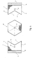
- Fig. 1 shows two clamping plates 1 and 2, which can be assembled into a vacuum clamping plate. Apart from a different floor plan, the two clamping plates 1 and 2 have the same structure, which is why the same reference numerals are used for the corresponding parts and the following description of the figures initially relates exclusively to the clamping plate 1.
- the partial clamping plate 1 has an essentially flat underside 3 facing away from the viewer, and an upper side 4 parallel to and at a distance from it.
- a total of five side surfaces 5, 6, 8 and 9 extend at right angles thereto between the top 4 and the bottom 3, which merge into one another at corners 11, 12, 13 and 15.
- the angle that the side surfaces 8 and 9 form at the corner 15 is 90 ° , as does the angle that the side surfaces 5 and 9 define at the corner 11.
- the angle between the sides 3 and 6 or between the side surfaces 7 and 8 at the corners 12 and 14 is 60 o in each case, so that the angle at the corner 13 is 240 o , ie there is a concave indentation of the partial clamping plate 1
- the side surfaces 3 ... 9 are flat, smooth surfaces without projections.
- T-groove 16 which is adjacent to the side surface 9 and runs parallel to it, which opens upwards and penetrates both the side surface 5 and the side surface 8.
- the grooves 17 and 18 do not quite lead to the side surfaces 5, 6, 7 and 8 and they also end at a distance from the edge of the T-groove 16, so that a narrow strip 23 is formed which, as a closed polygon, the field of framed pyramid-shaped ridges 19 completely and without interruption.
- the top of this bar 23, the surface of which is located on the outside of the partial clamping plate 1, is formed by the relevant side wall 5 ... 9, again in the plane of the plateau surfaces 22.
- the flat top 4 is of the type Grooves 17 and 18 pulled through and divided into small areas.
- the upper side 4 contains, in the middle between the side surfaces 5 and 8 and approximately in the middle between the corner 13 and the furthest point of the T-slot 16, a bore 26 which can be seen in FIG a valve 27.
- This valve 27 consists essentially of a outside cylindrical valve housing 28, which carries on the outer peripheral surface a fine thread, not shown in the drawing, with which it is screwed into a thread of the bore 26 in a gas-tight manner.
- a bore 31 is contained within the valve housing 28 and tapers towards the top 4 via a frustoconical shoulder 32 onto a bore section 33 with a smaller diameter.
- an essentially cylindrical valve closure member 34 which is displaceable longitudinally and carries an annular collar 35 approximately in the middle. The annular collar 35 serves to press an O-ring seal 36 against the frustoconical shoulder 32 in order to interrupt the flow path from the bore section 33 to the bore 31.
- valve closure member 34 continues upwards over the annular collar 35 in a cylindrical pin 37, which projects with its free end slightly beyond the plane defined by the upper side 4.
- a compression spring 38 acts against the underside of the collar 35, which is supported at the other end on an annular disk 39 pressed into the bore 31.
- valve closure member 34 is provided below the annular collar 35 with a blind bore 41 which is also penetrated by a transverse bore 41a below the annular collar 35.
- the bore 26 thus forms a channel via which the upper side 4 can be connected to the chamber 25 in terms of flow by means of the valve 27.
- the chamber 25, which is closed to the underside 3 with a screwed flat cover 40, via a further channel with each Side surfaces 5, 6, 7 and 8 connected.
- the mouth of this respective connecting channel is formed by an associated opening 42.
- the connecting channel leading away from the opening 42 consists of a stepped bore 43 which either opens directly into the circular chamber 25 or extends radially to the latter or which opens into a second auxiliary bore, not shown, which in turn leads to the chamber 25.
- the bores 43 which emanate from the two side surfaces 5 and 8 open directly into the chamber 25, while the stepped bores 43 emanating from the side surfaces 6 and 7 open into a bore which is not shown in any more detail and which is closed by a sealing plug (also not illustrated) which is attached starting from the side surface 5 or 8.
- a sealing plug also not illustrated
- the area of the hole 43 directly adjacent to the opening 42 has the shape that can be seen in FIG. 2.
- the stepped bore 43 following the mouth 42 consists of a section 44 with a large diameter, which merges with a flat annular shoulder 44 into a bore section 46 with a smaller diameter.
- the distance of the annular shoulder 45 from the mouth 42, ie from the associated side surface 5 ... 8 is always the same.
- a continuous threaded bore 47 penetrates into the bore section 4 from the underside 3.
- the threaded bore 47 serves to receive a stud screw 49 provided with a tip 48.
- the position of the orifices 42 in each side surface 5 ... 8 is selected so that when two clamping plates 1, 2 are congruent with their respective side surfaces, the orifices 42 and the bores 43 emanating therefrom at right angles are aligned.
- two fitting bores 51 are also symmetrically distributed next to each mouth 42, into which dowel pins (not shown) are inserted largely without play.
- coupling or connecting elements 52 are provided, which consist of an essentially cylindrical tube piece 53.
- the pipe section 53 is offset at its two ends, so that a cylindrical extension 54 of smaller diameter is formed, the outer diameter of which corresponds to the clear width of an O-ring 55 centered thereon and which is shorter than the O-ring 55 thick.
- the cylindrical base body 53 At a distance from the end faces, the cylindrical base body 53, the outer diameter of which is the inside diameter of the bore section 44, contains two trapezoidal annular grooves 56, the relative position of which can be found in detail from the following functional description.
- Mouths 42 which are not required are sealed by sealing plugs which have the outer shape of a "half" coupling piece 52 and not, like the coupling piece 52, are designed as a tube, but as a solid body.
- the connecting piece 58 illustrated in FIG. 5 is used to connect the partial clamping plate 1 or a vacuum plate constructed therefrom to a vacuum source. As far as it is the section seated in the bore section 44, it has the same shape as the "half" coupling piece 52, which is why the same reference numerals are used in this respect. Instead of the other half of the coupling piece 52, a threaded shoulder 61 is provided on the relevant end face 59, which merges into a nipple 62 with a smaller diameter. The entire coupling piece 58 is penetrated by a bore 63.
- the angle of the side surfaces 6 and 7 at the corner 13 is not 240 o , but 120 o , with the corner 13 projecting outwards and not , as with the clamping plate 1, is set back inside. Accordingly, the inner angles at the corners 12 and 14 are not, as previously 60 o , but 120 o .
- the grooves 17 run at right angles to the relevant side wall 7 or 6, while the grooves 18 run to this side wall 6 or 7 are parallel.
- a hexagonal partial clamping plate 65 shown in FIG. 3 is also provided in the new embodiment of a vacuum clamping plate, the outline of which has the shape of a regular hexagon.
- This partial clamping plate 65 is also delimited by an upper side 4 and an underside 3 which is parallel to the upper side 4.
- the thickness of the clamping plate 65 ie the distance of the plateau surfaces 22 formed on the upper side 4 from the underside 3 is the same as for the partial clamping plates 1 and 2 from FIG. 1.
- the only difference, apart from the changed corner angle, is the fact that on all side surfaces 5 ... 10, which are identical to one another, orifices 42 are provided, from which step bores 42 lead into the chamber 25 located inside the clamping plate 65.
- the partial clamping plates 1, 2 and 65 described so far can be assembled as follows to form a vacuum clamping plate of almost any size:
- the mouth 42 in the side surface 6 is similarly sealed by a plug which, as mentioned above, has the appearance of a "half" coupling piece 52 and is of solid construction. After inserting this sealing plug into the mouth 42, the sealing plug does not protrude beyond the side surface 6 in question.
- the opening 42 in the side surface 7 is closed in the same way as explained for the partial clamping plate 1.
- the mouth 42 in the side surface 6 is open.
- the partial clamping plate 2 with the still unclosed mouth 42 is pushed onto the coupling piece 52 protruding from the side surface 7, which penetrates into the step bore 43 in question.
- the two fitting bolts used also slide into the associated fitting bores 51 of the clamping plate 2.
- Fig. 2 shows the opposing side surfaces 6 and 7 immediately before plugging together.
- the stud screw 49 is screwed into the associated threaded bore 47 from the underside in order to positively fix the coupling piece 52 also in the other clamping plate 2 and to press it against the relevant annular shoulder 52.
- the two clamping plates 1 and 2 are mechanically positively connected to one another and there is also a coupling piece 52 a flow connection between the two chambers 25 of the two clamping plates 1 and 2.
- the position of the grooves 56 and the length of the coupling piece 52 is dimensioned so that when tightening the studs 49 on the one hand it is ensured that the O-rings 55 between the clamping plates 1 and 2 and the coupling piece 52 are clamped.
- the two clamping plates 1 and 2 with their side surfaces 6 and 7 abut each other without joints.
- the protruding corner 13 of the clamping plate 2 penetrates into the inwardly recessed corner 13 of the clamping plate 1.
- a vacuum clamping plate is obtained which has a rectangular outline, the top sides 4 and the lower parts 3 of the two clamping plates 1 and 2 being flush with one another.
- the side surface 5 merges smoothly and without jumping into the side surface 8 of the other partial clamping plate 1 or 2.
- the orifices 42 contained in the side faces 5 and 8 can now be sealed gas-tight with the exception of one, as described above, by means of sealing plugs.
- the connecting piece shown in FIG. 5 is only inserted into one of the orifices 42, in the same way as described above in connection with the coupling piece 52. A line leading to a vacuum source can now be connected to this connecting piece 58 in a known manner.
- the vacuum clamping plate prepared in this regard can now be attached to the machine table of a machine tool, for example with clamping claws or a magnetic clamping plate.
- a rubber cord is inserted into the grooves 17 and 18 of the two clamping plates 1 and 2, which corresponds to the outer contour of the workpiece to be clamped. Because of the joint between the two clamping plates 1 and 2, however, the total area of the workpiece is divided into two fields, with one field on one clamping plate and the other field on the other clamping plate.
- the circumferential bar 23 simplifies the insertion of the seal at the joint between the two clamping plates 1 and 2. It is only necessary to ensure that each field enclosed by a sealing cord also includes the valve 27 present there on the relevant clamping plate 1, 2.
- the workpiece If the workpiece is now placed on the vacuum clamping plate, it presses down the valve closure member 28 via the pin 33, as a result of which the flow connection between the underside of the workpiece and the vacuum chamber 25 is established.
- the vacuum source connected to the partial clamping plates 1, 2 can now be effective in order to pull the workpiece down on the upper side 4 and hold it there. Since not only the positive mechanical connection between the clamping plates 1 and 2 is established via the coupling piece 52, but also the flow connection, the same vacuum prevails in all vacuum chambers 25 of all clamping plates 1 and 2 without additional lines having to be connected externally.
- a vacuum plate composed only of the partial clamping plates 1 and 2 according to FIG. 1 should be too small, it is initially readily possible to attach further partial clamping plates 1 and 2 in addition to the partial clamping plates 1 and 2, that is to say on the side surfaces 5 and 8 two further clamping plates 1 and 2 are connected to one another as described above.
- the connection to the partial clamping plates 1 and 2 according to FIG. 1 then expediently takes place by means of coupling pieces 52, which are inserted both in the side surface 5 and in the side surface 8, in order to produce as many positive connections as possible.
- the flow connection is also established each time.
- the base body of the partial clamping plate 1, 2 or 65 is preferably made of light metal, which is why the cover 40, with which the vacuum chamber 25 is closed airtight, advantageously consists of a correspondingly strong circular steel plate which projects onto a shoulder projecting into the chamber 25 66 is screwed on in order to be able to hold the vacuum clamping plate composed of the partial clamping plates on a magnetic clamping plate, if necessary.
- the T-grooves 16 running on the outside are used as described in DE-PS 38 38 988.
- the grooves 17 and 18 can be provided with the cross-sectional profile shown in FIG. 7, in which they are slightly undercut in the vicinity of their groove base 69.
- the cross section of the grooves 17 and 18 consists of a parallel-flanked section 71, which is set back from the top 4 or the flat surface 22 and merges into a chamfer 72 towards the plateau surface 22.
- a slight concavity 73 is milled, in which the side wall of the groove springs back by approximately 0.1 mm to 0.3 mm compared to the parallel-flanked section 71.
- the sealing cords usually used made of closed-cell foam rubber thereby show a certain self-retention in the groove 17, 18 even when no forces push the seal into the groove 17, 18 from above.
- the effective plateau surface measures approximately 3 ⁇ 3 mm square and the groove width at the largest point as a result of the chamfer surfaces 72 is likewise approximately 3 mm.
- such undersized elevations 19 must not be missing in the transition areas, because the hold of the sealing cord would then be impaired.
Landscapes
- Engineering & Computer Science (AREA)
- Mechanical Engineering (AREA)
- Clamps And Clips (AREA)
- Quick-Acting Or Multi-Walled Pipe Joints (AREA)
- Preparing Plates And Mask In Photomechanical Process (AREA)
- Gripping On Spindles (AREA)
- Supports Or Holders For Household Use (AREA)
- Jigs For Machine Tools (AREA)
- Particle Accelerators (AREA)
Applications Claiming Priority (2)
| Application Number | Priority Date | Filing Date | Title |
|---|---|---|---|
| DE4302440A DE4302440A1 (de) | 1993-01-29 | 1993-01-29 | Vakuumspannplatte |
| DE4302440 | 1993-01-29 |
Publications (2)
| Publication Number | Publication Date |
|---|---|
| EP0608528A1 true EP0608528A1 (fr) | 1994-08-03 |
| EP0608528B1 EP0608528B1 (fr) | 1996-09-04 |
Family
ID=6479166
Family Applications (1)
| Application Number | Title | Priority Date | Filing Date |
|---|---|---|---|
| EP93119946A Expired - Lifetime EP0608528B1 (fr) | 1993-01-29 | 1993-12-10 | Plaque de serrage à vide |
Country Status (6)
| Country | Link |
|---|---|
| US (1) | US5405123A (fr) |
| EP (1) | EP0608528B1 (fr) |
| AT (1) | ATE142140T1 (fr) |
| CA (1) | CA2114086A1 (fr) |
| DE (2) | DE4302440A1 (fr) |
| ES (1) | ES2092213T3 (fr) |
Cited By (4)
| Publication number | Priority date | Publication date | Assignee | Title |
|---|---|---|---|---|
| WO1996004102A1 (fr) * | 1994-08-02 | 1996-02-15 | Tobias Michael Cardew | Dispositifs de fixation par le vide |
| FR2773342A1 (fr) * | 1998-01-02 | 1999-07-09 | Christian Leviel | Dispositif de presse fonctionnant par depression |
| CN108857892A (zh) * | 2018-08-01 | 2018-11-23 | 吉林大学 | 金相试样夹持装置 |
| WO2022243302A1 (fr) * | 2021-05-18 | 2022-11-24 | Homag Bohrsysteme Gmbh | Segment de retenue pour un dispositif porte-pièce, dispositif porte-pièce et machine d'usinage |
Families Citing this family (21)
| Publication number | Priority date | Publication date | Assignee | Title |
|---|---|---|---|---|
| IT1269344B (it) * | 1994-04-21 | 1997-03-26 | Cerim Spa Off Mec | Dispositivo di posizionamento e bloccaggio di suole e macchina con esso |
| US5584254A (en) * | 1994-05-16 | 1996-12-17 | Williams; Willis R. | Collapsible work bench apparatus |
| US5868846A (en) * | 1997-08-20 | 1999-02-09 | Mcneil-Ppc, Inc. | Vacuum nozzle assembly |
| DE19921071B4 (de) * | 1998-10-20 | 2006-07-13 | J. Schmalz Gmbh | Vorrichtung zur Kombination unterschiedlicher Vakuumspannsysteme zum Zwecke des gemeinsamen Betriebes |
| DE10023323A1 (de) * | 2000-05-12 | 2001-11-29 | Karl Goeckel | Tisch- oder konsolenartige Spanneinrichtung |
| US6827803B1 (en) | 2002-03-20 | 2004-12-07 | John A. Willis | Method of joining belt ends |
| JP4946523B2 (ja) * | 2007-03-07 | 2012-06-06 | セイコーエプソン株式会社 | 生産システム用汎用セル及び該汎用セルを用いた生産システム |
| TWI409133B (zh) * | 2008-06-27 | 2013-09-21 | Hon Hai Prec Ind Co Ltd | 夾持裝置 |
| DE102008049912A1 (de) * | 2008-10-02 | 2010-04-08 | Tobias Krebs | Vakuum-Spannvorrichtung sowie Spanngerät für Langmaterial wie Stangen und Rohre |
| US8393028B2 (en) * | 2009-04-23 | 2013-03-12 | Nike, Inc. | Method of manufacturing footwear having sipes |
| DE202009014858U1 (de) | 2009-12-15 | 2010-03-04 | HFH Präzisionsmechanik GmbH | Vorrichtung zum Aufspannen von Werkstücken |
| DE202010011276U1 (de) | 2010-08-06 | 2010-12-02 | Weidling Gmbh | Vorrichtung zum Spannen von flächigen Materialien auf Plottmaschinen mit Schneid- und Fräseinrichtungen |
| DE102011080118B4 (de) * | 2011-07-29 | 2016-08-18 | Schunk Gmbh & Co. Kg Spann- Und Greiftechnik | Nullpunktspannstation |
| US9010827B2 (en) * | 2011-11-18 | 2015-04-21 | Nike, Inc. | Switchable plate manufacturing vacuum tool |
| US8849620B2 (en) | 2011-11-18 | 2014-09-30 | Nike, Inc. | Automated 3-D modeling of shoe parts |
| US8752751B2 (en) * | 2012-07-13 | 2014-06-17 | Asm Technology Singapore Pte Ltd | Lead frame support plate and window clamp for wire bonding machines |
| JP2014058018A (ja) * | 2012-09-18 | 2014-04-03 | Honda Motor Co Ltd | 基準座 |
| PL237424B1 (pl) * | 2018-09-21 | 2021-04-19 | Politechnika Wroclawska | Sposób tłumienia drgań samowzbudnych elementów cienkościennych podczas obróbki skrawaniem |
| CN112223157A (zh) * | 2020-10-13 | 2021-01-15 | 扬州永瑞机械有限公司 | 一种用于平键加工的快速夹紧装置 |
| CN114654280B (zh) * | 2022-04-20 | 2025-01-07 | 抚州联创恒泰光电有限公司 | Cnc加工件固定治具及其制作方法 |
| CN115246105B (zh) * | 2022-08-15 | 2025-03-28 | 湖北华尔升智能装备有限公司 | 一种方便对工件限位的真空箱用定位模 |
Citations (6)
| Publication number | Priority date | Publication date | Assignee | Title |
|---|---|---|---|---|
| US2729040A (en) * | 1954-02-10 | 1956-01-03 | Boeing Co | Vacuum chuck jigs |
| US4066249A (en) * | 1977-05-11 | 1978-01-03 | Grumman Aerospace Corporation | Modular vacuum work area |
| EP0175295A1 (fr) * | 1984-09-19 | 1986-03-26 | Horst Witte Entwicklungs- und Vertriebs-KG | Dispositif de serrage sous vide pour fixer des pièces à usiner sur des établis, des tables ou similaires |
| DE3437604A1 (de) * | 1984-10-13 | 1986-04-17 | Armin 7101 Langenbrettach Sautter | Verbindungselement fuer bauteile eines raster-spann-systems |
| DE3838988C1 (en) * | 1988-11-18 | 1989-12-07 | Heinz Mielenz Gmbh, Cnc-Bearbeitung, 7316 Koengen, De | Vacuum clamping device |
| DE4000099A1 (de) * | 1990-01-04 | 1991-07-11 | Fraunhofer Ges Forschung | Vorrichtung zum aufspannen von werkstuecken mittels unterdruck |
Family Cites Families (9)
| Publication number | Priority date | Publication date | Assignee | Title |
|---|---|---|---|---|
| US3720433A (en) * | 1970-09-29 | 1973-03-13 | Us Navy | Manipulator apparatus for gripping submerged objects |
| US4139051A (en) * | 1976-09-07 | 1979-02-13 | Rockwell International Corporation | Method and apparatus for thermally stabilizing workpieces |
| US4551192A (en) * | 1983-06-30 | 1985-11-05 | International Business Machines Corporation | Electrostatic or vacuum pinchuck formed with microcircuit lithography |
| DE3434328A1 (de) * | 1984-09-19 | 1986-04-17 | Hoechst Ag, 6230 Frankfurt | Verfahren zum galvanischen trennen der elektrolytfuehrenden sammelleitungen von den elektrolytraeumen eines elektrochemischen zellenpaketes |
| US4684113A (en) * | 1984-09-28 | 1987-08-04 | The Boeing Company | Universal holding fixture |
| US4881727A (en) * | 1987-08-06 | 1989-11-21 | Joseph Deutsch | Clamping mechanism |
| DE3837516A1 (de) * | 1988-11-04 | 1990-05-10 | Pfaff Ind Masch | Werktisch zum vorbereiten eines flaechenhaften verbundwerkstuecks |
| US5234205A (en) * | 1992-01-15 | 1993-08-10 | Shanley Stephen F | Quick die change clamp |
| US5226636A (en) * | 1992-06-10 | 1993-07-13 | International Business Machines Corporation | Holding fixture for substrates |
-
1993
- 1993-01-29 DE DE4302440A patent/DE4302440A1/de not_active Ceased
- 1993-12-10 DE DE59303654T patent/DE59303654D1/de not_active Expired - Fee Related
- 1993-12-10 ES ES93119946T patent/ES2092213T3/es not_active Expired - Lifetime
- 1993-12-10 AT AT93119946T patent/ATE142140T1/de not_active IP Right Cessation
- 1993-12-10 EP EP93119946A patent/EP0608528B1/fr not_active Expired - Lifetime
-
1994
- 1994-01-24 US US08/184,987 patent/US5405123A/en not_active Expired - Fee Related
- 1994-01-24 CA CA002114086A patent/CA2114086A1/fr not_active Abandoned
Patent Citations (6)
| Publication number | Priority date | Publication date | Assignee | Title |
|---|---|---|---|---|
| US2729040A (en) * | 1954-02-10 | 1956-01-03 | Boeing Co | Vacuum chuck jigs |
| US4066249A (en) * | 1977-05-11 | 1978-01-03 | Grumman Aerospace Corporation | Modular vacuum work area |
| EP0175295A1 (fr) * | 1984-09-19 | 1986-03-26 | Horst Witte Entwicklungs- und Vertriebs-KG | Dispositif de serrage sous vide pour fixer des pièces à usiner sur des établis, des tables ou similaires |
| DE3437604A1 (de) * | 1984-10-13 | 1986-04-17 | Armin 7101 Langenbrettach Sautter | Verbindungselement fuer bauteile eines raster-spann-systems |
| DE3838988C1 (en) * | 1988-11-18 | 1989-12-07 | Heinz Mielenz Gmbh, Cnc-Bearbeitung, 7316 Koengen, De | Vacuum clamping device |
| DE4000099A1 (de) * | 1990-01-04 | 1991-07-11 | Fraunhofer Ges Forschung | Vorrichtung zum aufspannen von werkstuecken mittels unterdruck |
Cited By (4)
| Publication number | Priority date | Publication date | Assignee | Title |
|---|---|---|---|---|
| WO1996004102A1 (fr) * | 1994-08-02 | 1996-02-15 | Tobias Michael Cardew | Dispositifs de fixation par le vide |
| FR2773342A1 (fr) * | 1998-01-02 | 1999-07-09 | Christian Leviel | Dispositif de presse fonctionnant par depression |
| CN108857892A (zh) * | 2018-08-01 | 2018-11-23 | 吉林大学 | 金相试样夹持装置 |
| WO2022243302A1 (fr) * | 2021-05-18 | 2022-11-24 | Homag Bohrsysteme Gmbh | Segment de retenue pour un dispositif porte-pièce, dispositif porte-pièce et machine d'usinage |
Also Published As
| Publication number | Publication date |
|---|---|
| ES2092213T3 (es) | 1996-11-16 |
| ATE142140T1 (de) | 1996-09-15 |
| US5405123A (en) | 1995-04-11 |
| EP0608528B1 (fr) | 1996-09-04 |
| DE4302440A1 (de) | 1994-08-11 |
| CA2114086A1 (fr) | 1994-07-30 |
| DE59303654D1 (de) | 1996-10-10 |
Similar Documents
| Publication | Publication Date | Title |
|---|---|---|
| EP0608528B1 (fr) | Plaque de serrage à vide | |
| DE102014119482B4 (de) | Werkzeugspanneinrichtung, Werkzeughalter und Werkzeugträger | |
| AT500177B1 (de) | Wiederholgenaue spanneinrichtung | |
| DE69706127T2 (de) | Vorgesteuertes Umschaltventil | |
| EP2629936B1 (fr) | Système de serrage à point zéro | |
| DE4307437C2 (de) | Anschlußvorrichtungen für Rohrleitungen | |
| DE20000895U1 (de) | Spanneinrichtung | |
| DE10002395B4 (de) | Spanneinrichtung | |
| DE29823473U1 (de) | Vakuumspannsystem | |
| EP0753368A1 (fr) | Dispositif de serrage pour la fixation relative précise de 2 pièces | |
| DE102012104263A1 (de) | Kühlmittelverteiler für eine Werkzeugmaschine | |
| DE2260938A1 (de) | Als baublock ausgebildeter ventilverteilerkoerper | |
| DE3341542A1 (de) | Spanneinrichtung zur verwendung an oder in bearbeitungsstationen von werkzeugmaschinen | |
| DE2805040A1 (de) | In eine gewindebohrung eingeschraubtes entsperrbares rueckschlagventil | |
| EP0175295A1 (fr) | Dispositif de serrage sous vide pour fixer des pièces à usiner sur des établis, des tables ou similaires | |
| EP0275923A2 (fr) | Dispositif de serrage de pièces | |
| DE3838988C1 (en) | Vacuum clamping device | |
| DE3705123A1 (de) | Automatisches werkzeug-wechselsystem | |
| DE3713023C2 (de) | Vorrichtung zum Spannen von Paletten | |
| EP0849034B1 (fr) | Dispositif d'accouplement | |
| DE10039072A1 (de) | Ventilanordnung | |
| DE4039241A1 (de) | Drehschieber fuer vakuumleitungen | |
| DE9421996U1 (de) | Anschlußvorrichtung zum Anschluß eines Heizkörpers und Patrone zum Einbau in diese | |
| DE19621261A1 (de) | Dichtungsanordnung | |
| DE3309786C1 (de) | T-förmiges Verschlußstück zum Einsetzen in eine T-förmige Aufspann-Nut eines Werkzeugmaschinentisches |
Legal Events
| Date | Code | Title | Description |
|---|---|---|---|
| PUAI | Public reference made under article 153(3) epc to a published international application that has entered the european phase |
Free format text: ORIGINAL CODE: 0009012 |
|
| AK | Designated contracting states |
Kind code of ref document: A1 Designated state(s): AT BE CH DE DK ES FR GB GR IE IT LI LU MC NL PT SE |
|
| 17P | Request for examination filed |
Effective date: 19941231 |
|
| 17Q | First examination report despatched |
Effective date: 19950707 |
|
| GRAH | Despatch of communication of intention to grant a patent |
Free format text: ORIGINAL CODE: EPIDOS IGRA |
|
| GRAH | Despatch of communication of intention to grant a patent |
Free format text: ORIGINAL CODE: EPIDOS IGRA |
|
| GRAA | (expected) grant |
Free format text: ORIGINAL CODE: 0009210 |
|
| AK | Designated contracting states |
Kind code of ref document: B1 Designated state(s): AT BE CH DE DK ES FR GB GR IE IT LI LU MC NL PT SE |
|
| PG25 | Lapsed in a contracting state [announced via postgrant information from national office to epo] |
Ref country code: GR Free format text: LAPSE BECAUSE OF FAILURE TO SUBMIT A TRANSLATION OF THE DESCRIPTION OR TO PAY THE FEE WITHIN THE PRESCRIBED TIME-LIMIT Effective date: 19960904 Ref country code: GB Effective date: 19960904 Ref country code: DK Effective date: 19960904 |
|
| REF | Corresponds to: |
Ref document number: 142140 Country of ref document: AT Date of ref document: 19960915 Kind code of ref document: T |
|
| ITF | It: translation for a ep patent filed | ||
| REG | Reference to a national code |
Ref country code: CH Ref legal event code: NV Representative=s name: KIRKER & CIE SA |
|
| ET | Fr: translation filed | ||
| REF | Corresponds to: |
Ref document number: 59303654 Country of ref document: DE Date of ref document: 19961010 |
|
| REG | Reference to a national code |
Ref country code: IE Ref legal event code: FG4D Free format text: 69713 |
|
| REG | Reference to a national code |
Ref country code: ES Ref legal event code: FG2A Ref document number: 2092213 Country of ref document: ES Kind code of ref document: T3 |
|
| PG25 | Lapsed in a contracting state [announced via postgrant information from national office to epo] |
Ref country code: SE Effective date: 19961204 Ref country code: PT Effective date: 19961204 |
|
| PG25 | Lapsed in a contracting state [announced via postgrant information from national office to epo] |
Ref country code: AT Effective date: 19961210 |
|
| PG25 | Lapsed in a contracting state [announced via postgrant information from national office to epo] |
Ref country code: LU Free format text: LAPSE BECAUSE OF NON-PAYMENT OF DUE FEES Effective date: 19961231 Ref country code: LI Effective date: 19961231 Ref country code: CH Effective date: 19961231 Ref country code: BE Effective date: 19961231 |
|
| GBV | Gb: ep patent (uk) treated as always having been void in accordance with gb section 77(7)/1977 [no translation filed] |
Effective date: 19960904 |
|
| PG25 | Lapsed in a contracting state [announced via postgrant information from national office to epo] |
Ref country code: IE Free format text: LAPSE BECAUSE OF NON-PAYMENT OF DUE FEES Effective date: 19970416 |
|
| REG | Reference to a national code |
Ref country code: IE Ref legal event code: FD4D Ref document number: 69713 Country of ref document: IE |
|
| PG25 | Lapsed in a contracting state [announced via postgrant information from national office to epo] |
Ref country code: MC Effective date: 19970630 |
|
| PLBE | No opposition filed within time limit |
Free format text: ORIGINAL CODE: 0009261 |
|
| STAA | Information on the status of an ep patent application or granted ep patent |
Free format text: STATUS: NO OPPOSITION FILED WITHIN TIME LIMIT |
|
| REG | Reference to a national code |
Ref country code: CH Ref legal event code: PL |
|
| 26N | No opposition filed | ||
| PGFP | Annual fee paid to national office [announced via postgrant information from national office to epo] |
Ref country code: FR Payment date: 19971120 Year of fee payment: 5 |
|
| PGFP | Annual fee paid to national office [announced via postgrant information from national office to epo] |
Ref country code: ES Payment date: 19971212 Year of fee payment: 5 |
|
| PGFP | Annual fee paid to national office [announced via postgrant information from national office to epo] |
Ref country code: DE Payment date: 19971217 Year of fee payment: 5 |
|
| PG25 | Lapsed in a contracting state [announced via postgrant information from national office to epo] |
Ref country code: NL Free format text: LAPSE BECAUSE OF NON-PAYMENT OF DUE FEES Effective date: 19980701 |
|
| NLV4 | Nl: lapsed or anulled due to non-payment of the annual fee |
Effective date: 19980701 |
|
| PG25 | Lapsed in a contracting state [announced via postgrant information from national office to epo] |
Ref country code: ES Free format text: LAPSE BECAUSE OF EXPIRATION OF PROTECTION Effective date: 19981211 |
|
| PG25 | Lapsed in a contracting state [announced via postgrant information from national office to epo] |
Ref country code: FR Free format text: LAPSE BECAUSE OF NON-PAYMENT OF DUE FEES Effective date: 19990831 |
|
| REG | Reference to a national code |
Ref country code: FR Ref legal event code: ST |
|
| PG25 | Lapsed in a contracting state [announced via postgrant information from national office to epo] |
Ref country code: DE Free format text: LAPSE BECAUSE OF NON-PAYMENT OF DUE FEES Effective date: 19991001 |
|
| REG | Reference to a national code |
Ref country code: ES Ref legal event code: FD2A Effective date: 20010301 |
|
| PG25 | Lapsed in a contracting state [announced via postgrant information from national office to epo] |
Ref country code: IT Free format text: LAPSE BECAUSE OF NON-PAYMENT OF DUE FEES;WARNING: LAPSES OF ITALIAN PATENTS WITH EFFECTIVE DATE BEFORE 2007 MAY HAVE OCCURRED AT ANY TIME BEFORE 2007. THE CORRECT EFFECTIVE DATE MAY BE DIFFERENT FROM THE ONE RECORDED. Effective date: 20051210 |