EP0608587A1 - Sélection de fréquence par mesurer la qualité dans un système radio TDMA avec intervalles temporels composés d'une partie traffic et d'une partie test - Google Patents
Sélection de fréquence par mesurer la qualité dans un système radio TDMA avec intervalles temporels composés d'une partie traffic et d'une partie test Download PDFInfo
- Publication number
- EP0608587A1 EP0608587A1 EP93250033A EP93250033A EP0608587A1 EP 0608587 A1 EP0608587 A1 EP 0608587A1 EP 93250033 A EP93250033 A EP 93250033A EP 93250033 A EP93250033 A EP 93250033A EP 0608587 A1 EP0608587 A1 EP 0608587A1
- Authority
- EP
- European Patent Office
- Prior art keywords
- transceiver
- frequency
- traffic
- transmitting
- probe
- Prior art date
- Legal status (The legal status is an assumption and is not a legal conclusion. Google has not performed a legal analysis and makes no representation as to the accuracy of the status listed.)
- Ceased
Links
Images


Classifications
-
- H—ELECTRICITY
- H04—ELECTRIC COMMUNICATION TECHNIQUE
- H04B—TRANSMISSION
- H04B7/00—Radio transmission systems, i.e. using radiation field
- H04B7/24—Radio transmission systems, i.e. using radiation field for communication between two or more posts
- H04B7/26—Radio transmission systems, i.e. using radiation field for communication between two or more posts at least one of which is mobile
- H04B7/2643—Radio transmission systems, i.e. using radiation field for communication between two or more posts at least one of which is mobile using time-division multiple access [TDMA]
Definitions
- the present invention is related to a network of transceivers attempting communication in high frequency ranges which do not have stable propagation characteristics. More specifically, it is related to an approach which minimizes the time required to establish communications between two transceivers in a high frequency network.
- Adaptive TDMA (time division multiple access) communication systems have been previously designed which dynamically maintain potentially different frequencies between nodes of the communication system using a process of communicating the quality of received signals between the nodes and storing this information so that an optimum frequency band can be selected, whereby whenever signal quality deteriorates, an alternate frequency can be selected to provide continued communications.
- An example of such a system is shown in an already issued U.S. Patent #4,937,822, dated 26 June, 1990, and assigned to the same assignee as the present invention.
- the system outlined in the referenced patent utilized a connectivity phase which could only start a connectivity process on twelve minute intervals distributed at predetermined times throughout the day, and the process used required checking each of a number of prospective frequencies before deciding which signal would be appropriate to use in initial communications.
- a connectivity phase which could only start a connectivity process on twelve minute intervals distributed at predetermined times throughout the day, and the process used required checking each of a number of prospective frequencies before deciding which signal would be appropriate to use in initial communications.
- propagation characteristics were unfavorable and other sets of potential frequencies needed to be tried, the connection process could take much longer than could be tolerated in a practical operating environment where nodes of the network need, for some reason or another, to be off-line from time to time and then need to suddenly access the system.
- Each of the nodes operates from a precise clock as was the case in the referenced patent. Further, each of the nodes use a common algorithm such that each node knows exactly what frequency would be attempted by a given neighbor node if that neighbor node were to be transmitting at that time. Thus, each operating node continuously checks a set of frequencies for receipt of signal from other nodes, whether or not the other nodes are operating at that time, to see if start-up is commencing.
- each of the nodes transmits unique preamble signals that identify the source of the transmission, when a given node receives such a transmission identifiable as belonging to a previously assigned neighbor, that node henceforth provides information in transmissions to the node coming on line as to the frequency of the first signal heard, as long as the quality of the signal meets minimum standards of quality.
- a connection is declared, and traffic data is transmitted as appropriate.
- the system continues to search for better frequencies (higher quality) to use in future traffic situations but in the meantime, traffic data can be delivered.
- the protocol of the present invention is such that half of each transmission and reception time is used for maintenance purposes in trying out new frequencies, and the other half is available for traffic data.
- the traffic data portion and the maintenance portion are at different frequencies, and both the traffic data portion and the maintenance portion are used to provide information to the receiving node as to the frequency to be used for future traffic data as well as the quality of signals received recently on the traffic frequencies.
- the present concept in typical situations has reduced the connectivity phase from as much as 12 to 24 minutes down to less than two minutes. Typical situations show a drastic improvement since the present invention can declare connectivity and start transmitting traffic data as soon as the new entry into the system (or a node which has lost synchronization for whatever reason) hears from an assigned neighbor and successfully transmits to that neighbor.
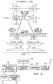
- a plurality of nodes 10, 12, 14 and 16 are shown comprising a portion of a TDMA network of N nodes.
- each node has the capability of directly contacting each of four other nodes in the network.
- a minor cycle, as illustrated below the nodes, comprises eight time slots.
- time slot T2 is used to transmit signals from node A to node C and time slot T6 is used for node A receiving signals from node C.
- Time slot T2 is broken down into two portions 18 and 20 while time slot T6 is broken down into portions 22 and 24.
- the five seconds designated as the time for time slot T2 is also typically broken into two 2.5 second time slots.
- a dash line block 26 is shown representative of the fact that the entire time slot T2 may (on an exceptional basis in the present invention) be used for a single purpose such as delivery of traffic data.
- a similar dash line block 28 represents a long packet combination for the receive time slot T6.
- E or emergency time slots which are not pertinent to the present invention.
- the entire minor cycle thus requires 40 seconds for the assigned time slots T1 through T8, and eight additional seconds for the four emergency time slots.
- a minor cycle uses up 48 seconds of time.
- FIG. 2 illustrates that the main cycle of the prior art communication link-up, traffic, and maintenance algorithm was separated into distinct modes with blocks 30, 32 and 34 representing respectively, the probe portion, traffic portion, and maintenance portions of a main cycle.
- the probe portion 30 was broken down into a sub-probe section 36, a response section 38, and a verify section 40.
- the sub-probe and response portions each required 4.8 minutes, and the verify portion required 2.4 minutes.
- the total time for sending out the various trial frequencies, checking the response, and verifying the information consumed twelve minutes.
- the device would then proceed to the traffic mode with occasional temporary advances to a maintenance mode to update usable frequencies before returning to a traffic mode. This required that such a connectivity phase in the prior art system could only start at prescribed twelve minute intervals or five times per hour.
- a first waveform or timing representation 50 illustrates a minor cycle previously illustrated in Figure 1. It indicates that in the first four traffic slots node A transmits first to node B, then to node C, then to node D, and then to node E. In the last four traffic slots of the minor cycle, the node receives signals from B, C, D, and E. Timing representation 52 indicates that each of the five second time slots for transmission or reception is divided into a traffic slot, and a probe slot each of 2.5 seconds.
- a timing representation 54 expands upon timing representation 52 and shows, for a typical five second slot, that during start-up the traffic slot may have a two second or "long" preamble, and the remaining portion of the two and one-half second time slot contains probe and traffic (P&T) control data.
- the probe slot also has a long, two second preamble, and the remaining time comprises probe and traffic data identical to that in the traffic slot.
- the probe and traffic data in one embodiment of the invention, comprised a frequency index, an order wire index, an acknowledgement sequence number, whether or not the apparatus is in a start-up state, and link quality analysis information.
- the frequencies used in the probe slot are taken from a list, which is maintained the same at all of the nodes.
- the nodes have the same frequency-time algorithm and are synchronized, so that pairs of them can switch to the same transmission/receive frequencies at designated times.
- the frequency for transmission in the traffic slot may be taken from a default frequency list known at both ends.
- the default frequencies may be selected one time by a designer of the system as the most likely to succeed frequency for the link or path type.
- An improvement is to use multiple default frequencies which are cycled through.
- the default frequency table may be modified by a prediction algorithm designed to use recent probe results to select the actual frequencies to be used in the traffic slot at the next occurrence of start-up.
- a prediction program designed to use recent probe results to select the actual frequencies to be used in the traffic slot at the next occurrence of start-up.
- Such a modification could employ a prediction program whose accuracy (for the next 24 hours) can be greatly improved by measuring the channel propagation characteristics, in a manner similar to that done with the probe signals, and updating the model with the measured value of the highest frequency found to propagate. This would result in the model's input sun spot number being modified to force it to predict the MUF (maximum usable frequency) as measured. Once this pseudo sun spot number has been determined and exchanged between nodes, both affected transceivers will provide a prediction of the same frequency.
- Timing representation 56 shows the composition of the time slot after link-up, with the traffic slot having a "short” or .28 second preamble, P&T control data, and then user (traffic) data.
- the probe time slot remains the same as it did during start-up.
- the frequencies of the traffic slot use the optimum measured frequencies after link-up, and changes to new frequencies when so directed to track changes in propagation characteristics of the environment.
- the probe slot on the other hand, after link-up, continues to probe at frequencies from a predetermined internal list, but in accordance with the overall algorithm of the invention, the list may be modified after link-up by direction of an intelligent maintenance module to be later discussed.
- FIG 4 information is presented as to communications between only nodes A and B at a time defined as 60. As illustrated, time is passing in a vertical direction down the figure. At the time indicated as 60, the node A is in a receive mode expecting signals from node B, and node B is accordingly in a transmit mode. As illustrated, a frequency F4, is transmitted at time 60, and at time 62 a probe frequency is transmitted at frequency F1. For the purposes of discussion, it may be assumed that propagation characteristics are such that node A receives the probe frequency F1 successfully (the received signal meets selected minimum quality standards), and due to propagation effects or whatever, the frequency F4 is not successfully received from node B by node A.
- node A Having successfully received on frequency F1, node A selects F1 at its traffic (receive) frequency. It now will set its receive frequency to F1 and announce the traffic frequency to node B. This decisive action is called by the inventors "announce-and-do.”
- node A does transmit traffic on the frequency F4 announcing that it has successfully received frequency F1 or, in other words, that the frequency F1 works.
- Node B receives this message on frequency F4.
- node A transmits a probe signal at frequency F1 announcing that it is able to successfully receive frequency F1 from B.
- node A has successfully heard frequency F1
- node B has successfully heard frequency F4.
- node B can announce frequency F4 and set to receive on F4, both nodes can send traffic.
- node B uses the F1 traffic frequency to announce that frequency F4 works.
- Node A which has switched to receive on frequency F1 for future traffic, successfully receives the message.
- node B transmits a probe at frequency F2 announcing that F4 works, and as illustrated, the probe signal is not successfully received by node A, which is attempting in accordance with an internal algorithm to receive at frequency F2.
- node A transmits a traffic signal at frequency F4 in accordance with the received announcement at time 68, and node B receives the traffic at its traffic frequency F4.
- the next probe signal from node A to node B occurs at time 74. As illustrated, node B does not successfully receive this probe signal on frequency F2.
- Figure 5 illustrates a situation where the node A adaptively changes its traffic receiving frequency.
- node B transmits traffic on frequency F1 as previously set up in Figure 4.
- node B transmits a probe on frequency F3 in accordance with an internal algorithm, and node A successfully receives the probe, and upon analysis, determines that the quality of the signal F3 is better than the quality of the signal received on frequency F1.
- node A in its transmit condition uses the previously set traffic frequency F4 to announce to B that it wants to receive future traffic signals on F3. Node B receives this traffic signal successfully.
- node A on its probe portion of the time slot announces frequency F3 as its desired frequency, and transmits on probe frequency F3.
- Node B does not successfully receive probe frequency F3 according to the illustration.
- node B in a new minor cycle transmits traffic on F3 as opposed to the previous minor cycle where it used the previously set F1 for the traffic frequency.
- node A in its receive traffic portion of the time slot uses F3 for the first time, and the frequency again works.
- Node B at time 90 transmits a probe on probe frequency F4 which is not successfully received by node A.
- Figure 6 illustrates an example in which the time required to declare link-up is relatively long if it happens that the default frequencies used in the traffic time slot did not successfully propagate, and the first successful probe frequency is fa3 from node A to node B.
- probe fb4 is successfully received from node B by node A.
- traffic can be sent in minor cycle 5. It must be realized that traffic being sent in minor cycle 5 immediately after both nodes have received successfully a probe signal from the other under the present "announce-and-do" approach, is, at the very least, one complete minor cycle faster than any known prior art.
- the prior art would typically have a required minimum minor cycle 5 to acknowledge successful receipt of a probe signal in both directions before being able to transfer usable traffic in minor cycle 6.
- the heavy dash line is an indication of the link-up capabilities in an "announce-and-do" mode presented by the present inventive concept, whereas the lighter dashed line between minor cycles 5 and 6 is an indication of the soonest possible declaration of link-up under prior art protocols.
- Figure 7 further illustrates the same environmental conditions as confronted by the example of Figure 6, except that in this situation a predicted frequency is used in the first time slot as opposed to a default frequency.
- the predictive frequency happens to be equivalent to fa3 for node A, and happens to be equivalent to fb4 for node B.
- both nodes will receive the signal occurring in the traffic slot from the other node in the first minor cycle.
- link-up is established by the end of minor cycle 1 and traffic can commence operation in minor cycle 2.
- link-up could not be established prior to the end of minor cycle 2.
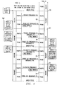
- a block 100 is shown as a combination network controller which implements the intelligent maintenance module and P & T protocol. It exchanges data with an end user I/O block 102 which could be something as simple as a keyboard and screen from which the operator transmits and receives messages, or any other device for originating and receiving messages.
- Block 100 is connected to a modem/radio controller 104 which receives time of day information from a block 106 entitled "TOD Subsystem".
- Block 100 is also connected to a receive signal measurement/storage block 108 which receives signals and provides storage of the measurements made until the stored information is to be used or transmitted to other nodes.
- Block 104 is connected to a transceiver block 110 which provides signals to a power amplifier 112. Power amplifier 112 is connected to an antenna 114 for transmission of messages or reception of messages from other nodes.
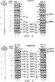
- Figure 9 provides a high level flow diagram of the operation of the block 100 of Figure 8 wherein upon start-up for communication between any given pair of nodes, the apparatus goes from a start-up block 120 to a block 122, clearing a working frequency database of any prior information. The apparatus then goes to block 124 where the traffic frequency is set to some predicted value (if predictive values are to be used), and then the system proceeds to block 126 to choose probe and traffic frequencies. If the system is in a start-up condition, the traffic frequency is already set by block 124, and the probe frequencies are derived from a known time-related list of probe frequencies comprising part of an internal algorithm. The adaptive nature of the system allows the probe frequencies and the traffic frequencies to change, thus the choosing in block 126 is a continually changing operation.
- the system ascertains whether the next time slot for communications with a given node is to be a transmit or receive time slot. If it is a transmit time slot, the apparatus continues to block 130, and builds a transmit packet including information relating to the node's newest addition to the set of traffic frequencies. It also includes an acknowledgement of the neighbor's last announced addition to the set of traffic frequencies. It further includes a summary of the receive quality of each frequency in the present node's set of traffic frequencies, and finally, includes a flag indicating whether or not the node is in a start-up state. This packet of information relating to protocol is transmitted twice, once on the probe frequency and once on the transmit frequency, in accordance with block 132.
- the traffic frequency uses a long preamble in the start-up condition.
- the system proceeds to block 134, where if either a probe or traffic packet or both are successfully received, the frequency or frequencies are added to the working frequency database.
- the protocol information received in either one or both packets is processed, and based upon the analysis of the data, or the information in the packet, frequencies are added to or replaced in the set of traffic frequencies in the working frequency database. Further, any user data obtained in the traffic packet is passed to a higher level protocol for transmission to the end user controller represented by block 100 and storage 108 in Figure 8.
- the system proceeds to a decision block 136 where it checks to see whether the neighbor announced that it is in a start-up state. If so, the system returns to block 124 to set the traffic frequency to a predicted value, but if the neighbor is not in the start-up state, control returns to block 126 to choose the next probe and traffic frequencies.
- the protocol comprised a minor cycle occurring every 48 seconds having four two-second emergency slots and eight five-second transmit or receive intervals divided into two and one-half second packets, as in the present invention. After a number of frequencies were checked and connection was made, the full five seconds, less preamble time, was devoted to traffic. From time to time after link up, the probe was reintroduced to update the knowledge of useable frequencies.
- the system of the present invention is generally faster to link up than the prior art system. In addition, it is more stable in operation, since it is more adaptive to changing propagation characteristics. Most applications of the present concept rate a robust system much higher on a value scale than volume of traffic at any given time. If there is an emergency where large volumes of traffic data need to be transmitted for a short period of time, the five-second time slot can be dedicated to traffic on an exceptional basis, modifying either the traffic preamble or the data in the P&T control data portion of the slot so that the receiver knows that the data will pre-empt the succeeding probe portion of the time slot.
- the system is continually checking the signal quality of both the traffic data and the probe signals, and as soon as a new frequency signal is received with a signal-to-noise ratio indicating better propagation, the system is modified to operate at the new frequency.
- the totality of signal quality information stored in block 108 of Figure 8 is utilized by the intelligent maintenance module portion of block 100 to determine which frequencies should be used by the traffic signals and in what order.
- the intelligent maintenance module also is the source of instructions for attempting new probe frequencies outside the predetermined library of probe frequencies.
- the measurements of the receive characteristics of the traffic and probe packets of information may be stored in a database that forms a propagation history of every frequency successfully received.
- Measurements of signal-to-noise ratio (SNR) and cyclic redundancy code (CRC) error check are used by the intelligent maintenance module 100 of Figure 8 to constantly select the best working frequencies.
- Measurements of TOA (time of arrival) and automatic gain control (AGC) setting are used to maximize the receiver's chance of acquiring synchronization with the signal on any particular frequency.
- the CRC measurement is used to detect data errors induced during the transmission. If errors are detected, the data portion of that particular traffic packet is ignored.
- the CRC measurement is also factored into the weighted signal-to-noise ratio average used to select the best working frequencies. Thus, a CRC error on a received packet for a particular frequency lowers the weighted signal-to-noise ratio average for that frequency.
- the TOA is a relative measure of propagation delay and can be an indicator of the propagation mode. In other words, which ionospheric support layer was used and how many hops the signal traversed enters into the time of arrival.
- the search algorithm in the receiver can be seeded with this value to shorten the time it takes for the acquisition of synchronization on that frequency, thereby allowing the use of a shorter preamble such as shown in block 56 of Figure 3 wherein the traffic packet has room for user data capacity in addition to the P&T control data.
- the present invention also provides the capability of examining the quality of received signals and adjusting the data rate downward when the signal-to-noise ratio indicates poor signal quality or upward when the quality is high.
- the power can be increased when the signal-to-noise ratio is poor or reduced when the signal-to-noise ratio rises. The reduction in power provides a benefit in using less power at each node if it is battery operated, or provides less interference to other nearby nodes and reduces the possibility of reception by unauthorized receivers.
- This P&T packet includes the frequency being confirmed and an order wire index specifying which of several order wire reception frequencies is being replaced, with the possibility of setting more than one or all order wire reception frequencies to the same frequency.
- the intelligent maintenance module 100 then monitors the status of the frequency confirmation process to know when it is safe to make another selection.
- a node can change a receive frequency every P&T cycle.
- Its "announce-and-do" frequency change protocol is an implementation of a more general protocol designated as a "Reciprocal Parameter Change” (RPC) protocol.
- RPC Reciprocal Parameter Change
- the RPC protocol is used to establish parameters that must be know at both ends of a link before they will work.
- the present protocol algorithm in effect states that any new parameter becomes effective immediately, and the node will continue announcing the parameter until it is ready to change to another.
- the rate of occurrence of the probe dynamically or permanently reduced so as to provide more slots for user traffic data.
- the system may complete a probe set, such as 48 different frequency bands, and then announce (using the control data section of the P&T transmissions) to each neighbor independently an indication of the frequency of probe transmissions desired.
- a second alternate embodiment approach is to turn off probing entirely at some point after an adequate number of traffic frequencies have been selected and are being successfully used.
- a bit can be set in the control data portion of the traffic packet to inform the other node that probing is being temporarily resumed.
- the degradation depending upon environmental conditions, may take several hours or a few minutes, depending upon time of day and overall propagation conditions.
- the nodes can then immediately start transmitting probes again. Since both ends of a given link monitor the probe set frequencies in the probe slots after turning off the probes, either end can start retransmitting at any time and expect to be heard. The resumption of probing may be continued until satisfactory new traffic frequencies are found and the requesting node sets a bit to stop probing again.
- Time efficiency of start-up is enhanced by permitting synchronization to start in any minor cycle rather than waiting for a prescribed time, by using predictive frequencies in addition to a library of frequencies where the predictive frequency is based upon some type of experience algorithm, and by placing the probe frequencies in groups so that the probe process quickly covers the available band in discrete, but broad, jumps.
- the data rate and/or power of transmission may be modified in accordance with the quality of signal transmissions received to optimize the data rate or other appropriate data signal reception characteristics.
Landscapes
- Engineering & Computer Science (AREA)
- Computer Networks & Wireless Communication (AREA)
- Signal Processing (AREA)
- Mobile Radio Communication Systems (AREA)
Priority Applications (2)
| Application Number | Priority Date | Filing Date | Title |
|---|---|---|---|
| EP93250033A EP0608587A1 (fr) | 1993-01-27 | 1993-01-27 | Sélection de fréquence par mesurer la qualité dans un système radio TDMA avec intervalles temporels composés d'une partie traffic et d'une partie test |
| AU32100/93A AU653669B2 (en) | 1993-01-27 | 1993-01-28 | Skywave adaptable network transceiver apparatus and method using a stable probe and traffic protocol |
Applications Claiming Priority (2)
| Application Number | Priority Date | Filing Date | Title |
|---|---|---|---|
| EP93250033A EP0608587A1 (fr) | 1993-01-27 | 1993-01-27 | Sélection de fréquence par mesurer la qualité dans un système radio TDMA avec intervalles temporels composés d'une partie traffic et d'une partie test |
| AU32100/93A AU653669B2 (en) | 1993-01-27 | 1993-01-28 | Skywave adaptable network transceiver apparatus and method using a stable probe and traffic protocol |
Publications (1)
| Publication Number | Publication Date |
|---|---|
| EP0608587A1 true EP0608587A1 (fr) | 1994-08-03 |
Family
ID=25622013
Family Applications (1)
| Application Number | Title | Priority Date | Filing Date |
|---|---|---|---|
| EP93250033A Ceased EP0608587A1 (fr) | 1993-01-27 | 1993-01-27 | Sélection de fréquence par mesurer la qualité dans un système radio TDMA avec intervalles temporels composés d'une partie traffic et d'une partie test |
Country Status (2)
| Country | Link |
|---|---|
| EP (1) | EP0608587A1 (fr) |
| AU (1) | AU653669B2 (fr) |
Citations (2)
| Publication number | Priority date | Publication date | Assignee | Title |
|---|---|---|---|---|
| WO1988004496A1 (fr) * | 1986-12-02 | 1988-06-16 | Plessey Overseas Limited | Systeme de transmission de donnees avec demande de repetition automatique |
| EP0462572A2 (fr) * | 1990-06-18 | 1991-12-27 | Nortel Networks Corporation | Protocole d'accès multiples |
Family Cites Families (1)
| Publication number | Priority date | Publication date | Assignee | Title |
|---|---|---|---|---|
| US4937822A (en) * | 1989-06-27 | 1990-06-26 | Rockwell International Corporation | Skywave adaptable communication apparatus |
-
1993
- 1993-01-27 EP EP93250033A patent/EP0608587A1/fr not_active Ceased
- 1993-01-28 AU AU32100/93A patent/AU653669B2/en not_active Ceased
Patent Citations (2)
| Publication number | Priority date | Publication date | Assignee | Title |
|---|---|---|---|---|
| WO1988004496A1 (fr) * | 1986-12-02 | 1988-06-16 | Plessey Overseas Limited | Systeme de transmission de donnees avec demande de repetition automatique |
| EP0462572A2 (fr) * | 1990-06-18 | 1991-12-27 | Nortel Networks Corporation | Protocole d'accès multiples |
Also Published As
| Publication number | Publication date |
|---|---|
| AU653669B2 (en) | 1994-10-06 |
| AU3210093A (en) | 1994-08-04 |
Similar Documents
| Publication | Publication Date | Title |
|---|---|---|
| US5359595A (en) | Skywave adaptable network transceiver apparatus and method using a stable probe and traffic protocol | |
| US5204855A (en) | Skywave adaptable network transceiver apparatus | |
| US5850605A (en) | Method and apparatus for dynamically grouping transmitters for message transmission in a communication system | |
| US5737330A (en) | System and method for the efficient control of a radio communications network | |
| EP0677940B1 (fr) | Surveillance de transfert dans un réseau de communication à sauts de fréquence lents | |
| US7583933B2 (en) | Dynamic frequency selection in a wireless communication network | |
| HU217719B (hu) | Eljárás frekvenciaugrásos rádiókommunikációt használó vezeték nélküli hálózatban az ugrás meghatározására | |
| EP0945037A2 (fr) | Dispositif et procede permettant de controler une liaison d'egal a egal dans un reseau sans fil a commande centralisee | |
| WO2003024129A1 (fr) | Systeme de communications faisant appel a un dispositif de selection de frequence dynamique | |
| US9264995B2 (en) | System and method for mobile terminal initiated communications | |
| US6842625B2 (en) | Method for autonomous frequency management for reliable data communications | |
| US5768260A (en) | Device for changing the transmission parameters in a radio transmitter | |
| CN112492556B (zh) | 无线传感器网络和关联请求发送方法 | |
| US8588101B2 (en) | Method and arrangement for reducing the average time needed for a communication unit to connect to a communication network | |
| US5204856A (en) | Skywave adaptable network transceiver apparatus using predictive frequencies for initial link-up | |
| JP2006197559A (ja) | 無線通信機及び無線チャネル測定管理端末 | |
| EP1111947A1 (fr) | Système de téléphonie sans fil | |
| JPH08237729A (ja) | 移動通信システムの基地局における干渉状態監視方法 | |
| US5563918A (en) | Method of selecting optimum frequency in skywave communication apparatus | |
| AU653669B2 (en) | Skywave adaptable network transceiver apparatus and method using a stable probe and traffic protocol | |
| IL104514A (en) | Method and a system for maintaining communication between two transceivers | |
| US5530913A (en) | Message delivery improvement for data communications system using single frequency reuse networks | |
| US5936947A (en) | Mobile communication system and control channel setting method in mobile communication system | |
| US6738619B1 (en) | Base transceiver station equipment and radio subsystem | |
| JPH07123317B2 (ja) | 移動通信における接続制御方式 |
Legal Events
| Date | Code | Title | Description |
|---|---|---|---|
| PUAI | Public reference made under article 153(3) epc to a published international application that has entered the european phase |
Free format text: ORIGINAL CODE: 0009012 |
|
| 17P | Request for examination filed |
Effective date: 19940301 |
|
| AK | Designated contracting states |
Kind code of ref document: A1 Designated state(s): DE FR GB IT SE |
|
| GRAG | Despatch of communication of intention to grant |
Free format text: ORIGINAL CODE: EPIDOS AGRA |
|
| 17Q | First examination report despatched |
Effective date: 19961227 |
|
| 18R | Application refused |
Effective date: 19970616 |