EP0608742A2 - Echangeur de chaleur en particulier pour être utilisé comme évaporateur étagère dans des réfrigérateurs ou des congélateurs - Google Patents
Echangeur de chaleur en particulier pour être utilisé comme évaporateur étagère dans des réfrigérateurs ou des congélateurs Download PDFInfo
- Publication number
- EP0608742A2 EP0608742A2 EP94100569A EP94100569A EP0608742A2 EP 0608742 A2 EP0608742 A2 EP 0608742A2 EP 94100569 A EP94100569 A EP 94100569A EP 94100569 A EP94100569 A EP 94100569A EP 0608742 A2 EP0608742 A2 EP 0608742A2
- Authority
- EP
- European Patent Office
- Prior art keywords
- coil
- heat exchanger
- shelf
- supporting
- disconnected
- Prior art date
- Legal status (The legal status is an assumption and is not a legal conclusion. Google has not performed a legal analysis and makes no representation as to the accuracy of the status listed.)
- Granted
Links
- 239000002184 metal Substances 0.000 claims abstract description 4
- 238000004519 manufacturing process Methods 0.000 description 6
- 238000005452 bending Methods 0.000 description 5
- 238000003466 welding Methods 0.000 description 4
- 230000008901 benefit Effects 0.000 description 3
- 238000004026 adhesive bonding Methods 0.000 description 2
- 238000010168 coupling process Methods 0.000 description 1
- 230000007547 defect Effects 0.000 description 1
- 238000007599 discharging Methods 0.000 description 1
- 230000000694 effects Effects 0.000 description 1
- 230000000670 limiting effect Effects 0.000 description 1
- 239000000463 material Substances 0.000 description 1
- 238000012986 modification Methods 0.000 description 1
- 230000004048 modification Effects 0.000 description 1
- 238000004806 packaging method and process Methods 0.000 description 1
- 238000005057 refrigeration Methods 0.000 description 1
- 238000004381 surface treatment Methods 0.000 description 1
Images

Classifications
-
- F—MECHANICAL ENGINEERING; LIGHTING; HEATING; WEAPONS; BLASTING
- F25—REFRIGERATION OR COOLING; COMBINED HEATING AND REFRIGERATION SYSTEMS; HEAT PUMP SYSTEMS; MANUFACTURE OR STORAGE OF ICE; LIQUEFACTION SOLIDIFICATION OF GASES
- F25D—REFRIGERATORS; COLD ROOMS; ICE-BOXES; COOLING OR FREEZING APPARATUS NOT OTHERWISE PROVIDED FOR
- F25D25/00—Charging, supporting, and discharging the articles to be cooled
- F25D25/02—Charging, supporting, and discharging the articles to be cooled by shelves
- F25D25/028—Cooled supporting means
Definitions
- the present invention relates to a heat exchanger, particularly for use as a rack evaporator in refrigerators or freezers.
- Refrigerators which are constituted by a box-like structure inside which a plurality of mutually stacked and spaced shelves is arranged to support the goods to be preserved.
- each shelf is constituted by a coil evaporator formed by means of a tubular body extending along a path that forms bends alternated with straight and substantially mutually co-planar portions.
- a structure is furthermore associated with the coil of each shelf and may be constituted by rods welded to the coils or by a plate-like element which is seamed or rigidly connected (for example by welding or glueing or other known rigid coupling methods) to the associated coil and has the purpose of forming a supporting surface for the products to be arranged on the shelves and, at the same time, of increasing the heat exchange surface of the coil.
- the coils of the various shelves are formed by means of one or more tubular bodies which are variously folded so as to form the straight portions and the bends of each coil and mutually connect the coils of the various shelves.
- the aim of the present invention is to solve the problems described above by providing a heat exchanger, particularly for use as a rack evaporator in refrigerators or freezers, in which it is possible to perform the desired torsion of the tube portion or portions of the various coils to obtain the stacked configuration of the various shelves without discharging stresses onto the rod structure rigidly associated with the coils.
- an object of the invention is to provide a heat exchanger, particularly for use as a rack evaporator, that can be obtained with limited production times and/or costs with respect to the production times required by conventional rack evaporators, whether manufactured with multiple separate and subsequently assembled shelves or with multiple shelves obtained from a single continuous tube.
- Another object of the invention is to provide a heat exchanger particularly for use as a rack evaporator which can have a lower defect rate and thus better general quality with respect to known evaporators.
- a heat exchanger particularly for use as a rack evaporator in refrigerators or freezers, of the type comprising a plurality of stacked shelves and comprising for each shelf: a coil, constituted by a tubular body extending along a path with bends alternated with straight and substantially mutually co-planar portions and by a supporting structure composed of metal rods welded to said coil and forming, above said coil, a supporting surface which is substantially parallel to the plane of arrangement of the coil, characterized in that said coil has, for each shelf, at least one portion disconnected from said supporting and/or heat-exchange enhancement structure, said at least one portion lying substantially parallel to the longer straight portions of the coil and proximate to one side of the shelf, said portion disconnected from the supporting structure being connected to a tubular portion that mutually connects the coils of two shelves which are not mutually co-planar.
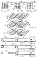
- the heat exchanger according to the present invention is composed of a plurality of stacked shelves 2, 2a and comprises, for each shelf 2, 2a, a coil 3, 3a to which a supporting and/or heat-exchange enhancement structure 4, 4a is connected; said supporting and/or heat-exchange enhancement structure is constituted by a plurality of parallel rods that are associated by welding to the various branches of the coil 3, 3a, and forms a supporting surface which is parallel to the plane of arrangement of the associated coil.
- each coil which forms one of the shelves of the exchanger, is preferably constituted by a single tubular body extending along a path with bends alternated with straight and mutually parallel and substantially co-planar portions.
- the coil 3, 3a of each shelf is contained within an ideal rectangle, and the longer straight portions of the coil are arranged parallel to two opposite sides of this ideal rectangle.
- the coils of the various shelves 2, 2a are mutually connected by a tubular portion 6, 6a, and the branch 7, 7a which is connected to this portion 6, 6a and lies substantially parallel and proximate to one side of the shelf and is disconnected from the supporting structure 4, 4a.
- branches 7, 7a that are disconnected from the supporting structure 4, 4a and are arranged at two mutually opposite and parallel sides of each shelf.
- the two branches 7, 7a that are disconnected from the supporting structure 4, 4a are furthermore parallel to the longer straight portions of the coil in a same shelf, and their distance from the closest longer straight portion is preferably less than the distance between the various longer straight portions of the coil that are rigidly connected to the supporting structure 4, 4a.
- the expression "disconnected from the supporting structure” is to be understood as meaning that the branches 7, 7a are not rigidly connected to the supporting structure 4, 4a.
- This condition can be provided by the fact that the branches 7, 7a are not affected at all by the supporting structure 4, 4a, as shown in particular in figures 1 to 5, but also by the fact that the rods composing the structure 4, 4a are simply curled or bent or kept in contact with the branches 7, 7a, as shown in detail in figures 6 to 8, without thereby preventing torsional rotation of the branch 7, 7a with respect to these rods.
- the heat exchanger according to the invention by bending a single tubular body, forming the various coils 3, 3a and the connecting portion 6, 6a on a same plane and subsequently applying, by welding or glueing, the supporting and/or heat-exchange enhancement structure 4, 4a. Then, by bending the portions 6, 6a with respect to the coils constituting the various shelves of the evaporator, the various coils are stacked. It should be noted that the bending of the portions 6, 6a that mutually connect the various coils can produce stresses that discharge onto the branches 7, 7a of the coils which are thus disconnected from the supporting structure 4, 4a. In this manner, the stresses that discharge onto the branches 7, 7a are not transmitted to the supporting structure 4, 4a, which preserves its planarity without problems, and the connection of the supporting structure to the coil is unaffected.
- a further advantage is that the bending operations to stack the various coils that form the shelves of the heat exchanger are considerably simplified.
- the heat exchanger according to the invention has been conceived particularly for use as a rack evaporator, it can also be used as a simple heat exchanger, with the various coils arranged in planes having any orientation according to the requirements.
- the materials employed may be any according to the requirements and the state of the art.
Landscapes
- Engineering & Computer Science (AREA)
- Chemical & Material Sciences (AREA)
- Combustion & Propulsion (AREA)
- Physics & Mathematics (AREA)
- Mechanical Engineering (AREA)
- Thermal Sciences (AREA)
- General Engineering & Computer Science (AREA)
- Physical Or Chemical Processes And Apparatus (AREA)
- Heat-Exchange Devices With Radiators And Conduit Assemblies (AREA)
- Devices That Are Associated With Refrigeration Equipment (AREA)
Applications Claiming Priority (2)
| Application Number | Priority Date | Filing Date | Title |
|---|---|---|---|
| ITMI930110A IT1263812B (it) | 1993-01-25 | 1993-01-25 | Scambiatore di calore,particolarmente per l'impiego come evaporatore a ripiani in armadi frigoriferi o congelatori |
| ITMI930110 | 1993-01-25 |
Publications (3)
| Publication Number | Publication Date |
|---|---|
| EP0608742A2 true EP0608742A2 (fr) | 1994-08-03 |
| EP0608742A3 EP0608742A3 (en) | 1994-08-24 |
| EP0608742B1 EP0608742B1 (fr) | 1997-10-22 |
Family
ID=11364743
Family Applications (1)
| Application Number | Title | Priority Date | Filing Date |
|---|---|---|---|
| EP94100569A Expired - Lifetime EP0608742B1 (fr) | 1993-01-25 | 1994-01-17 | Echangeur de chaleur en particulier pour être utilisé comme évaporateur étagère dans des réfrigérateurs ou des congélateurs |
Country Status (10)
| Country | Link |
|---|---|
| US (1) | US5433087A (fr) |
| EP (1) | EP0608742B1 (fr) |
| JP (1) | JPH06265287A (fr) |
| AT (1) | ATE159581T1 (fr) |
| DE (1) | DE69406315T2 (fr) |
| ES (1) | ES2109517T3 (fr) |
| IT (1) | IT1263812B (fr) |
| NO (1) | NO179425C (fr) |
| SI (1) | SI9400038A (fr) |
| TR (1) | TR27441A (fr) |
Cited By (1)
| Publication number | Priority date | Publication date | Assignee | Title |
|---|---|---|---|---|
| ITTO20090323A1 (it) * | 2009-04-23 | 2010-10-24 | Drahtzug Stein Divisione Omim Div Isione Come S | Metodo per la realizzazione di un castello evaporante per celle frigorifere e castello evaporante così ottenuto. |
Families Citing this family (7)
| Publication number | Priority date | Publication date | Assignee | Title |
|---|---|---|---|---|
| US5586443A (en) * | 1995-09-20 | 1996-12-24 | Conair Corporation | Refrigerant conservation system and method |
| ITRM20030234A1 (it) * | 2003-05-12 | 2004-11-13 | Mkm Srl | Impianto sottopavimento per la distribuzione del calore. |
| US20070051127A1 (en) * | 2003-09-26 | 2007-03-08 | Ssw Holding Company, Inc. | Cooling tubes for shelving |
| CA2488898C (fr) * | 2004-06-01 | 2008-01-08 | Macpherson Engineering Inc. | Systeme de chauffage par rayonnement faisant appel a un generateur d'air pulse comme source de chaleur |
| KR100739196B1 (ko) * | 2006-01-04 | 2007-07-13 | 엘지전자 주식회사 | 핀-튜브 열교환기 |
| RU2314464C1 (ru) * | 2006-07-27 | 2008-01-10 | Государственное учреждение Краснодарский научно-исследовательский институт хранения и переработки сельскохозяйственной продукции | Испаритель для охлаждения теплоносителей |
| TR200804594A2 (tr) * | 2008-06-23 | 2010-01-21 | Bsh Ev Aletleri̇ San. Ve Ti̇c. A.Ş. | Buzdolabı |
Family Cites Families (5)
| Publication number | Priority date | Publication date | Assignee | Title |
|---|---|---|---|---|
| US2334284A (en) * | 1941-04-12 | 1943-11-16 | Nash Kelvinator Corp | Refrigerating apparatus |
| US2473508A (en) * | 1945-08-10 | 1949-06-21 | Collins Douglas | Freezer shelf construction |
| US3144079A (en) * | 1960-03-23 | 1964-08-11 | Reynolds Metals Co | Shelf structure including a conduit |
| GB2008733B (en) * | 1977-09-10 | 1982-09-08 | Fulton Ti Ltd | Reezer shelves |
| DE3331765C2 (de) * | 1983-09-02 | 1986-10-23 | Bosch-Siemens Hausgeräte GmbH, 8000 München | Verfahren zum Herstellen von Wärmetauschern, insbesondere für Haushalt-Gefriergeräte |
-
1993
- 1993-01-25 IT ITMI930110A patent/IT1263812B/it active IP Right Grant
-
1994
- 1994-01-14 US US08/181,491 patent/US5433087A/en not_active Expired - Fee Related
- 1994-01-17 EP EP94100569A patent/EP0608742B1/fr not_active Expired - Lifetime
- 1994-01-17 AT AT94100569T patent/ATE159581T1/de active
- 1994-01-17 ES ES94100569T patent/ES2109517T3/es not_active Expired - Lifetime
- 1994-01-17 DE DE69406315T patent/DE69406315T2/de not_active Expired - Fee Related
- 1994-01-20 NO NO940202A patent/NO179425C/no unknown
- 1994-01-24 TR TR00091/94A patent/TR27441A/xx unknown
- 1994-01-24 JP JP6005913A patent/JPH06265287A/ja active Pending
- 1994-01-25 SI SI9400038A patent/SI9400038A/sl unknown
Cited By (1)
| Publication number | Priority date | Publication date | Assignee | Title |
|---|---|---|---|---|
| ITTO20090323A1 (it) * | 2009-04-23 | 2010-10-24 | Drahtzug Stein Divisione Omim Div Isione Come S | Metodo per la realizzazione di un castello evaporante per celle frigorifere e castello evaporante così ottenuto. |
Also Published As
| Publication number | Publication date |
|---|---|
| ES2109517T3 (es) | 1998-01-16 |
| NO179425B (no) | 1996-06-24 |
| TR27441A (tr) | 1995-05-24 |
| NO940202L (no) | 1994-07-26 |
| IT1263812B (it) | 1996-09-03 |
| ITMI930110A1 (it) | 1994-07-25 |
| EP0608742A3 (en) | 1994-08-24 |
| EP0608742B1 (fr) | 1997-10-22 |
| ITMI930110A0 (it) | 1993-01-25 |
| JPH06265287A (ja) | 1994-09-20 |
| DE69406315D1 (de) | 1997-11-27 |
| ATE159581T1 (de) | 1997-11-15 |
| US5433087A (en) | 1995-07-18 |
| DE69406315T2 (de) | 1998-04-02 |
| NO179425C (no) | 1996-10-02 |
| NO940202D0 (no) | 1994-01-20 |
| SI9400038A (en) | 1994-09-30 |
Similar Documents
| Publication | Publication Date | Title |
|---|---|---|
| US5485732A (en) | Heat exchanger, particularly for use as a rack evaporator in refrigerators or freezers, and process for manufacturing it | |
| CA2130156C (fr) | Serpentin condenseur et methode de fabrication connexe | |
| US4369350A (en) | Electric defroster heater mounting arrangement for stacked finned refrigeration evaporator | |
| EP0608742B1 (fr) | Echangeur de chaleur en particulier pour être utilisé comme évaporateur étagère dans des réfrigérateurs ou des congélateurs | |
| US6467170B2 (en) | Tube for heat exchangers and method of manufacturing same | |
| US20080302518A1 (en) | Flat tube heat exchanger | |
| EP1974851B1 (fr) | Procédé de fabrication d'échangeurs de chaleur utilisables en tant qu'évaporateurs étagères statiques dans des réfrigérateurs ou des congélateurs | |
| GB2133518A (en) | Refrigerator evaporator system | |
| US2255512A (en) | Refrigerant evaporator | |
| US1996808A (en) | Refrigerating apparatus | |
| ITPN960065A1 (it) | Metodo per produrre uno scambiatore di calore per un apparecchio refrigerante e scambiatore di calore cosi' prodotto | |
| US3008304A (en) | Evaporator having a heating element in unit relation therewith | |
| US2869337A (en) | Refrigeration evaporator with clinch-type plates | |
| CN219986056U (zh) | 蒸发管流水化组件 | |
| CN216962161U (zh) | 液体料包搁置架 | |
| WO2011008245A1 (fr) | Aptitude à la réalisation d'un étage de lyophilisateur amélioré à l'aide de l'utilisation d'une forme ouverte ou de dispositifs d'espacement de contact linéaires | |
| JP2761589B2 (ja) | 熱交換器 | |
| US2052370A (en) | Evaporator | |
| US2847194A (en) | Refrigeration evaporator construction | |
| US1893321A (en) | Cooling unit for refrigerating systems |
Legal Events
| Date | Code | Title | Description |
|---|---|---|---|
| PUAI | Public reference made under article 153(3) epc to a published international application that has entered the european phase |
Free format text: ORIGINAL CODE: 0009012 |
|
| PUAL | Search report despatched |
Free format text: ORIGINAL CODE: 0009013 |
|
| AK | Designated contracting states |
Kind code of ref document: A2 Designated state(s): AT BE CH DE DK ES FR GB GR IE IT LI NL PT SE |
|
| AK | Designated contracting states |
Kind code of ref document: A3 Designated state(s): AT BE CH DE DK ES FR GB GR IE IT LI NL PT SE |
|
| 17P | Request for examination filed |
Effective date: 19950213 |
|
| 17Q | First examination report despatched |
Effective date: 19960322 |
|
| GRAG | Despatch of communication of intention to grant |
Free format text: ORIGINAL CODE: EPIDOS AGRA |
|
| GRAH | Despatch of communication of intention to grant a patent |
Free format text: ORIGINAL CODE: EPIDOS IGRA |
|
| GRAH | Despatch of communication of intention to grant a patent |
Free format text: ORIGINAL CODE: EPIDOS IGRA |
|
| GRAA | (expected) grant |
Free format text: ORIGINAL CODE: 0009210 |
|
| AK | Designated contracting states |
Kind code of ref document: B1 Designated state(s): AT BE CH DE DK ES FR GB GR IE IT LI NL PT SE |
|
| PG25 | Lapsed in a contracting state [announced via postgrant information from national office to epo] |
Ref country code: NL Free format text: LAPSE BECAUSE OF FAILURE TO SUBMIT A TRANSLATION OF THE DESCRIPTION OR TO PAY THE FEE WITHIN THE PRESCRIBED TIME-LIMIT Effective date: 19971022 Ref country code: LI Free format text: LAPSE BECAUSE OF FAILURE TO SUBMIT A TRANSLATION OF THE DESCRIPTION OR TO PAY THE FEE WITHIN THE PRESCRIBED TIME-LIMIT Effective date: 19971022 Ref country code: GR Free format text: LAPSE BECAUSE OF FAILURE TO SUBMIT A TRANSLATION OF THE DESCRIPTION OR TO PAY THE FEE WITHIN THE PRESCRIBED TIME-LIMIT Effective date: 19971022 Ref country code: DK Free format text: LAPSE BECAUSE OF NON-PAYMENT OF DUE FEES Effective date: 19971022 Ref country code: CH Free format text: LAPSE BECAUSE OF FAILURE TO SUBMIT A TRANSLATION OF THE DESCRIPTION OR TO PAY THE FEE WITHIN THE PRESCRIBED TIME-LIMIT Effective date: 19971022 Ref country code: BE Free format text: LAPSE BECAUSE OF FAILURE TO SUBMIT A TRANSLATION OF THE DESCRIPTION OR TO PAY THE FEE WITHIN THE PRESCRIBED TIME-LIMIT Effective date: 19971022 Ref country code: AT Free format text: LAPSE BECAUSE OF FAILURE TO SUBMIT A TRANSLATION OF THE DESCRIPTION OR TO PAY THE FEE WITHIN THE PRESCRIBED TIME-LIMIT Effective date: 19971022 |
|
| REF | Corresponds to: |
Ref document number: 159581 Country of ref document: AT Date of ref document: 19971115 Kind code of ref document: T |
|
| REG | Reference to a national code |
Ref country code: CH Ref legal event code: EP |
|
| REF | Corresponds to: |
Ref document number: 69406315 Country of ref document: DE Date of ref document: 19971127 |
|
| ET | Fr: translation filed | ||
| ITF | It: translation for a ep patent filed | ||
| PGFP | Annual fee paid to national office [announced via postgrant information from national office to epo] |
Ref country code: GB Payment date: 19980112 Year of fee payment: 5 Ref country code: ES Payment date: 19980112 Year of fee payment: 5 |
|
| PGFP | Annual fee paid to national office [announced via postgrant information from national office to epo] |
Ref country code: SE Payment date: 19980115 Year of fee payment: 5 |
|
| PGFP | Annual fee paid to national office [announced via postgrant information from national office to epo] |
Ref country code: FR Payment date: 19980116 Year of fee payment: 5 |
|
| REG | Reference to a national code |
Ref country code: ES Ref legal event code: FG2A Ref document number: 2109517 Country of ref document: ES Kind code of ref document: T3 |
|
| PG25 | Lapsed in a contracting state [announced via postgrant information from national office to epo] |
Ref country code: IE Free format text: LAPSE BECAUSE OF NON-PAYMENT OF DUE FEES Effective date: 19980117 |
|
| PG25 | Lapsed in a contracting state [announced via postgrant information from national office to epo] |
Ref country code: PT Free format text: LAPSE BECAUSE OF FAILURE TO SUBMIT A TRANSLATION OF THE DESCRIPTION OR TO PAY THE FEE WITHIN THE PRESCRIBED TIME-LIMIT Effective date: 19980122 |
|
| PGFP | Annual fee paid to national office [announced via postgrant information from national office to epo] |
Ref country code: DE Payment date: 19980227 Year of fee payment: 5 |
|
| NLV1 | Nl: lapsed or annulled due to failure to fulfill the requirements of art. 29p and 29m of the patents act | ||
| REG | Reference to a national code |
Ref country code: CH Ref legal event code: PL |
|
| PLBE | No opposition filed within time limit |
Free format text: ORIGINAL CODE: 0009261 |
|
| STAA | Information on the status of an ep patent application or granted ep patent |
Free format text: STATUS: NO OPPOSITION FILED WITHIN TIME LIMIT |
|
| 26N | No opposition filed | ||
| PG25 | Lapsed in a contracting state [announced via postgrant information from national office to epo] |
Ref country code: GB Free format text: LAPSE BECAUSE OF NON-PAYMENT OF DUE FEES Effective date: 19990117 |
|
| PG25 | Lapsed in a contracting state [announced via postgrant information from national office to epo] |
Ref country code: SE Free format text: LAPSE BECAUSE OF NON-PAYMENT OF DUE FEES Effective date: 19990118 Ref country code: ES Free format text: LAPSE BECAUSE OF EXPIRATION OF PROTECTION Effective date: 19990118 |
|
| GBPC | Gb: european patent ceased through non-payment of renewal fee |
Effective date: 19990117 |
|
| PG25 | Lapsed in a contracting state [announced via postgrant information from national office to epo] |
Ref country code: FR Free format text: LAPSE BECAUSE OF NON-PAYMENT OF DUE FEES Effective date: 19990930 |
|
| PG25 | Lapsed in a contracting state [announced via postgrant information from national office to epo] |
Ref country code: DE Free format text: LAPSE BECAUSE OF NON-PAYMENT OF DUE FEES Effective date: 19991103 |
|
| REG | Reference to a national code |
Ref country code: FR Ref legal event code: ST |
|
| REG | Reference to a national code |
Ref country code: ES Ref legal event code: FD2A Effective date: 20010601 |
|
| PG25 | Lapsed in a contracting state [announced via postgrant information from national office to epo] |
Ref country code: IT Free format text: LAPSE BECAUSE OF NON-PAYMENT OF DUE FEES;WARNING: LAPSES OF ITALIAN PATENTS WITH EFFECTIVE DATE BEFORE 2007 MAY HAVE OCCURRED AT ANY TIME BEFORE 2007. THE CORRECT EFFECTIVE DATE MAY BE DIFFERENT FROM THE ONE RECORDED. Effective date: 20050117 |