EP0608768A1 - Dispositif pour mouler du riz "sushi" pour la préparation de "nigiri-zushi" - Google Patents
Dispositif pour mouler du riz "sushi" pour la préparation de "nigiri-zushi" Download PDFInfo
- Publication number
- EP0608768A1 EP0608768A1 EP94100797A EP94100797A EP0608768A1 EP 0608768 A1 EP0608768 A1 EP 0608768A1 EP 94100797 A EP94100797 A EP 94100797A EP 94100797 A EP94100797 A EP 94100797A EP 0608768 A1 EP0608768 A1 EP 0608768A1
- Authority
- EP
- European Patent Office
- Prior art keywords
- molding
- upper mold
- utensil
- mold member
- cavity
- Prior art date
- Legal status (The legal status is an assumption and is not a legal conclusion. Google has not performed a legal analysis and makes no representation as to the accuracy of the status listed.)
- Granted
Links
- 238000000465 moulding Methods 0.000 title claims abstract description 42
- 235000007164 Oryza sativa Nutrition 0.000 title claims abstract description 29
- 235000009566 rice Nutrition 0.000 title claims abstract description 29
- 240000007594 Oryza sativa Species 0.000 title claims abstract 3
- 238000005192 partition Methods 0.000 claims abstract description 13
- 241000209094 Oryza Species 0.000 description 26
- 238000012986 modification Methods 0.000 description 4
- 230000004048 modification Effects 0.000 description 4
- 241000251468 Actinopterygii Species 0.000 description 2
- 239000000463 material Substances 0.000 description 2
- 238000005096 rolling process Methods 0.000 description 2
- YCKRFDGAMUMZLT-UHFFFAOYSA-N Fluorine atom Chemical compound [F] YCKRFDGAMUMZLT-UHFFFAOYSA-N 0.000 description 1
- 239000004743 Polypropylene Substances 0.000 description 1
- 230000000994 depressogenic effect Effects 0.000 description 1
- 229910052731 fluorine Inorganic materials 0.000 description 1
- 239000011737 fluorine Substances 0.000 description 1
- 238000003780 insertion Methods 0.000 description 1
- 230000037431 insertion Effects 0.000 description 1
- -1 polypropylene Polymers 0.000 description 1
- 229920001155 polypropylene Polymers 0.000 description 1
- 229920005989 resin Polymers 0.000 description 1
- 239000011347 resin Substances 0.000 description 1
- 235000015170 shellfish Nutrition 0.000 description 1
Images




Classifications
-
- A—HUMAN NECESSITIES
- A47—FURNITURE; DOMESTIC ARTICLES OR APPLIANCES; COFFEE MILLS; SPICE MILLS; SUCTION CLEANERS IN GENERAL
- A47J—KITCHEN EQUIPMENT; COFFEE MILLS; SPICE MILLS; APPARATUS FOR MAKING BEVERAGES
- A47J43/00—Implements for preparing or holding food, not provided for in other groups of this subclass
- A47J43/20—Shapes for preparing foodstuffs, e.g. meat-patty moulding devices, pudding moulds
Definitions
- the present invention relates to a utensil for molding sushi rice for use in preparing nigiri-zushi (slightly vinegared oval-shaped rice balls with sliced raw fish, etc. on), and more particularly to a utensil for molding sushi rice which has a split mold comprising a multi-cavity type lower mold member and a multi-cavity type upper mold member, and an outer frame for the split mold to removably fit in.
- Cooked sushi rice is molded with a utensil of the type mentioned by placing the lower mold member into the outer frame, filling the sushi rice into a recess defined by the outer frame and the lower mold member, leveling the top of the mass of rice flush with the upper edge of the outer frame as by a bar, inserting the upper mold member into the outer frame and pushing down the upper mold member until the upper mold member fits to the lower mold member, whereby the sushi rice is molded in conformity with the shape of the mold cavity.
- a plurality of rice moldings substantially equally compressed can be produced with ease.
- the rice molding is taken out from the molding utensil, and flesh or fish, shellfish or the like is placed on the molding to prepare nigiri-zushi.
- the so-called multi-cavity type molding utensil has a plurality of molding cavities in rows.
- Each corner portion extending in a vertical direction may be horizontally rounded or beveled in an attempt to produce a sushi molding having a contour similar to that obtained by hand-rolling the sushi rice.
- the horizontally rounded or beveled cavity corners pose the following problem.
- the intersection of crisscrossed partition walls defining the cavities has an end surface in the shape of a rhombus or the like.
- the rhombus-like end surface of intersection is so broad that the sushi rice becomes partly lodged between the end surfaces of intersections in the lower and upper mold members on downward movement of the upper mold member, thereby failing to be molded into the desired shape.
- An object of the present invention is to provide a multi-cavity type utensil for molding sushi rice for use in preparing nigiri-zushi, the utensil having molding cavities with horizontally rounded or beveled corners free of the problem that the sushi rice is lodged between the end surfaces of partition intersections in the upper and lower mold members.
- multi-cavity type used in this specification and the appended claims refers to a type of mold or molding utensil having molding cavities which are arranged in a plurality of rows and include at least one intersection of crisscrossed partition walls.
- horizontal rounded or beveled corner used herein means a cavity corner portion extending in a vertical direction and horizontally rounded or beveled.
- the present invention provides a multi-cavity type utensil for molding sushi rice for use in preparing nigiri-zushi, the molding utensil having a split mold comprising a lower mold member and an upper mold member, and an outer frame for the split mold to removably fit in, the lower and upper mold members each having molding cavities defined by partition walls, the molding cavities having one or more crisscrossed intersections of partition walls, the molding utensil being characterized in that the corners of the cavities are rounded or beveled at least in a vertical direction and that an upwardly and downwardly movable, spring-biased baffle piece is projected from the end surface of the intersection in at least one of the lower and upper mold members.
- spring-biased baffle piece used in the specification and the appended claims refers to a baffle piece having a spring arranged thereunder to return the piece to the original position after forced depression.
- the drawings show a molding utensil which includes a split mold 1 and an outer frame 2.
- the split mold 1 comprises a lower mold member 11 and an upper mold member 12.
- the lower mold member 11 and the upper mold member 12 are of the multi-cavity type wherein molding cavities 10 are provided in a plurality of rows.
- the outer frame 2 is rectangular and has its upper and lower sides left open for the split mold 1 to be freely inserted thereinto or withdrawn therefrom.
- the lower and upper mold members 11, 12 are of the multi-cavity type having molding cavities 10 as arranged in 2 rows of 2 cavities, namely a total of 4 cavities arranged.
- these mold members may be of the multicavity type with at least 3 cavities arranged in at least 3 rows.
- the cavities 10 as defined by partition walls 3, 3 in the lower and upper mold members 11, 12 have horizontally rounded or beveled corners.
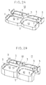
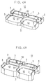
- the horizontally beveled corners are shown in FIGS. 2, A, B, FIGS. 3, A, B and FIGS. 4, A, B, and the horizontally rounded corners are depicted in FIGS. 5, A, B.
- the illustrated embodiments are of this type.
- FIG. 2, B shows an embodiment with the baffle piece 32 in the lower mold member 11
- FIG. 3, A shows an embodiment with the baffle piece 32 in the upper mold member 12
- FIGS. 4, A, B indicate an embodiment with the baffle pieces 32, 32 in the lower and upper mold members 11, 12, respectively.
- the baffle pieces 32, 32 in the lower and upper mold members 11, 12, respectively are so positioned as to strike against each other by the insertion of the lower and upper mold members 11, 12 into the outer frame 2.
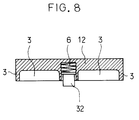
- the baffle piece 32 is spring-biased with a spring 6 so that when not depressed, the piece 32 protrudes in a vertical direction.
- the baffle piece 32 may be in the shape of a plate as shown in drawings.
- the piece 32 may be similar in the shape of end face to the intersection 31 or may be dissimilar thereto in the shape thereof, for example, may be in a rod-like shape.
- the baffle piece 32 when large in thickness or diameter, may be tapered in its entirety or at least in its forward end portion so as to sufficiently prevent the rice lodgment between the end surfaces of the intersections 31, 31.
- the baffle piece 32 is omitted in FIGS. 5, A, B. It goes without saying that the same baffle piece as described above is provided on the end surface of the intersection 31 in at least one of lower and upper mold members 11, 12 having cavity corners horizontally shaped as shown in FIGS. 5, A, B.
- the baffle pieces 32 in the lower and upper mold members 11, 12 as illustrated in FIGS. 5, A, B are disposed on the intersections 31 in the same manner as done for the piece 32 in the lower and upper mold members 11, 12 as shown in FIGS. 2, A, B, FIGS. 3, A, B and FIGS. 4, A, B.
- the molding utensil of the invention having the split mold 1 comprising the lower and upper mold members 11, 12, and the outer frame 2 is used in the manner mentioned to mold the sushi rice into a plurality of sushi moldings.
- a contour like one formed by hand-rolling the sushi rice is given the sushi molding due to the horizontally beveled or rounded corners of cavities 10 which are defined by the partition walls 3, 3 in the lower and upper mold members 11, 12.
- the baffle piece 32 provided on the intersection 31 of the lower or upper mold member 11 or 12 turns away the sushi rice thrusting against the baffle piece 32 until the baffle piece 32 is brought into contact with the end surface of the intersection 31 formed as opposed to the baffle piece 32.
- the top of the baffle piece 32 in one mold member is contacted with the end surface of the intersection 31 in the other mold member, whereupon the baffle piece 32 is gradually retracted in a specific direction by the downward movement of the upper mold member 12 against the spring 6 which is thereby compressed in a specific direction.
- the baffle pieces 32, 32 are provided in the lower and upper mold members 11, 12, the baffle pieces 32, 32 turn away the sushi rice thrusting thereaganist during the downward movement of the upper mold member 12.
- the sushi rice can be molded into nigiri-zushi as desired with substantially no sushi rice lodged between the flat and broad end surfaces of the intersections 31, 31 in the lower and upper mold members 11, 12.
- the baffle piece 32 is projected by about 5 mm to turn away the sushi rice to a satisfactory extent.
- the moldability of sushi moldings is enhanced by making the split mold 1, outer frame 2 and baffle piece 32 from a material of high releasability such as a fluorine-containing resin or polypropylene, or by applying such material of high releasability to the surfaces to be contacted with the sushi rice.
- a material of high releasability such as a fluorine-containing resin or polypropylene
- this invention provides a multi-cavity type utensil for molding sushi rice for use in preparing nigiri-zushi, the molding utensil having cavities with corners horizontally beveled or rounded free of the problem of sushi rice becoming lodged between the end surfaces of intersections in the lower and upper mold members.
Landscapes
- Engineering & Computer Science (AREA)
- Mechanical Engineering (AREA)
- Food Science & Technology (AREA)
- Cereal-Derived Products (AREA)
- Food-Manufacturing Devices (AREA)
Applications Claiming Priority (2)
| Application Number | Priority Date | Filing Date | Title |
|---|---|---|---|
| JP1993002123U JPH077748Y2 (ja) | 1993-01-29 | 1993-01-29 | 握りずし成形型 |
| JP2123/93U | 1993-01-29 |
Publications (2)
| Publication Number | Publication Date |
|---|---|
| EP0608768A1 true EP0608768A1 (fr) | 1994-08-03 |
| EP0608768B1 EP0608768B1 (fr) | 1997-01-02 |
Family
ID=11520581
Family Applications (1)
| Application Number | Title | Priority Date | Filing Date |
|---|---|---|---|
| EP94100797A Expired - Lifetime EP0608768B1 (fr) | 1993-01-29 | 1994-01-20 | Dispositif pour mouler du riz "sushi" pour la préparation de "nigiri-zushi" |
Country Status (4)
| Country | Link |
|---|---|
| US (1) | US5399082A (fr) |
| EP (1) | EP0608768B1 (fr) |
| JP (1) | JPH077748Y2 (fr) |
| DE (1) | DE69401282T2 (fr) |
Families Citing this family (5)
| Publication number | Priority date | Publication date | Assignee | Title |
|---|---|---|---|---|
| JP2804451B2 (ja) * | 1995-03-23 | 1998-09-24 | 日本碍子株式会社 | 複合碍子製造用圧縮成形金型 |
| US5910208A (en) * | 1998-10-27 | 1999-06-08 | Chiba And Associates | Boiled rice-shaping apparatus |
| WO2003047364A2 (fr) | 2001-11-29 | 2003-06-12 | Young Michael P | Appareil et procede de moulage de sushis |
| US20070048705A1 (en) * | 2005-09-01 | 2007-03-01 | Belter Dean M | Computerized accountability system for tracking student behavior |
| JP1680528S (fr) * | 2020-06-10 | 2021-03-08 |
Citations (4)
| Publication number | Priority date | Publication date | Assignee | Title |
|---|---|---|---|---|
| JPS5626166A (en) * | 1979-08-10 | 1981-03-13 | Mitsuyoshi Tanigawa | Hand-rolled "sushi" manufacturing machine |
| JPS5664757A (en) * | 1979-11-01 | 1981-06-02 | Okabe:Kk | Method and device for preparation of hand-shaped "sushi" or rice ball |
| US4437826A (en) * | 1982-07-30 | 1984-03-20 | Akitomi Tezuka | Rice-body shaping device for rolled sushi |
| US4853509A (en) * | 1987-11-18 | 1989-08-01 | Hario Kabushiki Kaisha | Rice cooker for microwave ranges |
Family Cites Families (5)
| Publication number | Priority date | Publication date | Assignee | Title |
|---|---|---|---|---|
| US1947124A (en) * | 1932-07-30 | 1934-02-13 | Charles A Clauss | Insert for waffle iron |
| US3741706A (en) * | 1972-01-26 | 1973-06-26 | Gen Mills Fun Group Inc | Toy molding device |
| GB2141372B (en) * | 1983-05-31 | 1986-12-31 | Kevin Robert Gower | Moulding apparatus |
| JPS61152224A (ja) * | 1984-12-27 | 1986-07-10 | 梶原工業株式会社 | 食品成形切断装置 |
| JPS6256111A (ja) * | 1985-09-05 | 1987-03-11 | Sony Corp | 樹脂封止金型 |
-
1993
- 1993-01-29 JP JP1993002123U patent/JPH077748Y2/ja not_active Expired - Lifetime
-
1994
- 1994-01-20 DE DE69401282T patent/DE69401282T2/de not_active Expired - Fee Related
- 1994-01-20 EP EP94100797A patent/EP0608768B1/fr not_active Expired - Lifetime
- 1994-01-25 US US08/186,320 patent/US5399082A/en not_active Expired - Fee Related
Patent Citations (4)
| Publication number | Priority date | Publication date | Assignee | Title |
|---|---|---|---|---|
| JPS5626166A (en) * | 1979-08-10 | 1981-03-13 | Mitsuyoshi Tanigawa | Hand-rolled "sushi" manufacturing machine |
| JPS5664757A (en) * | 1979-11-01 | 1981-06-02 | Okabe:Kk | Method and device for preparation of hand-shaped "sushi" or rice ball |
| US4437826A (en) * | 1982-07-30 | 1984-03-20 | Akitomi Tezuka | Rice-body shaping device for rolled sushi |
| US4853509A (en) * | 1987-11-18 | 1989-08-01 | Hario Kabushiki Kaisha | Rice cooker for microwave ranges |
Non-Patent Citations (2)
| Title |
|---|
| PATENT ABSTRACTS OF JAPAN vol. 5, no. 128 (C - 067) 18 August 1981 (1981-08-18) * |
| PATENT ABSTRACTS OF JAPAN vol. 5, no. 79 (C - 056) 23 May 1981 (1981-05-23) * |
Also Published As
| Publication number | Publication date |
|---|---|
| JPH0660390U (ja) | 1994-08-23 |
| US5399082A (en) | 1995-03-21 |
| EP0608768B1 (fr) | 1997-01-02 |
| JPH077748Y2 (ja) | 1995-03-01 |
| DE69401282T2 (de) | 1997-04-30 |
| DE69401282D1 (de) | 1997-02-13 |
Similar Documents
| Publication | Publication Date | Title |
|---|---|---|
| US5212853A (en) | Separable plastic fastener and method and apparatus for manufacturing thereof | |
| US6386854B1 (en) | Press for forming a compressible food item | |
| EP1693009A3 (fr) | Implant expansible pour l'embolisation vasculaire et méthode pour le fabriquer | |
| NZ509575A (en) | Process for producing masonry block with roughened surface using grate between mold portions, typically in form of raised expanded metal | |
| US5399082A (en) | Utensil for molding sushi rice for use in preparing nigiri-zushi | |
| JPS5630830A (en) | Extensive blow molding of bottole of synthetic resin with base cup | |
| US4123495A (en) | Method for making molded articles of expanded cellular material | |
| EP1366786A3 (fr) | Dé pouvant être ouvert | |
| CN110113973A (zh) | 用于容纳食品的模具 | |
| EP0669194A1 (fr) | Procédé et dispositif pour le moulage d'un produit comprenant un insert | |
| US4431394A (en) | Marshmallow mold | |
| JPH10316141A (ja) | 長さ可変の収納ケース及びその外ケースの製造に適する射出成形用金型 | |
| EP0594112A1 (fr) | Ustensile pour mouler du riz "sushi" à utiliser pour la préparation de "nigiri-zushi" | |
| JP3062105U (ja) | 寿司用包装容器 | |
| WO1997032537A1 (fr) | Conception d'un plateau de prise d'empreintes dentaires | |
| KR200443512Y1 (ko) | 어묵 제조기 | |
| JPS6243660B2 (fr) | ||
| JP2002225097A (ja) | 射出成形品 | |
| KR920003657Y1 (ko) | 절첩식 성형품 | |
| JPS5918977Y2 (ja) | トレイ | |
| JP2604179Y2 (ja) | 棒状物用容器 | |
| JP7406803B2 (ja) | 供試体型枠、及び、供試体製造方法 | |
| EP1264676A3 (fr) | Procédé de fabrication d'un emballage pour produits alimentaires et emballage fabriqué par ledit procédé | |
| GB2282986A (en) | Mould for the production of a dividable food product | |
| JPS6038869Y2 (ja) | 冷蔵庫の箱体 |
Legal Events
| Date | Code | Title | Description |
|---|---|---|---|
| PUAI | Public reference made under article 153(3) epc to a published international application that has entered the european phase |
Free format text: ORIGINAL CODE: 0009012 |
|
| AK | Designated contracting states |
Kind code of ref document: A1 Designated state(s): DE FR GB IT |
|
| 17P | Request for examination filed |
Effective date: 19941025 |
|
| 17Q | First examination report despatched |
Effective date: 19951121 |
|
| GRAG | Despatch of communication of intention to grant |
Free format text: ORIGINAL CODE: EPIDOS AGRA |
|
| GRAH | Despatch of communication of intention to grant a patent |
Free format text: ORIGINAL CODE: EPIDOS IGRA |
|
| GRAH | Despatch of communication of intention to grant a patent |
Free format text: ORIGINAL CODE: EPIDOS IGRA |
|
| GRAA | (expected) grant |
Free format text: ORIGINAL CODE: 0009210 |
|
| AK | Designated contracting states |
Kind code of ref document: B1 Designated state(s): DE FR GB IT |
|
| ITF | It: translation for a ep patent filed | ||
| ET | Fr: translation filed | ||
| REF | Corresponds to: |
Ref document number: 69401282 Country of ref document: DE Date of ref document: 19970213 |
|
| PLBE | No opposition filed within time limit |
Free format text: ORIGINAL CODE: 0009261 |
|
| STAA | Information on the status of an ep patent application or granted ep patent |
Free format text: STATUS: NO OPPOSITION FILED WITHIN TIME LIMIT |
|
| 26N | No opposition filed | ||
| REG | Reference to a national code |
Ref country code: GB Ref legal event code: IF02 |
|
| PGFP | Annual fee paid to national office [announced via postgrant information from national office to epo] |
Ref country code: FR Payment date: 20041230 Year of fee payment: 12 |
|
| PGFP | Annual fee paid to national office [announced via postgrant information from national office to epo] |
Ref country code: GB Payment date: 20050119 Year of fee payment: 12 |
|
| PGFP | Annual fee paid to national office [announced via postgrant information from national office to epo] |
Ref country code: DE Payment date: 20050127 Year of fee payment: 12 |
|
| PG25 | Lapsed in a contracting state [announced via postgrant information from national office to epo] |
Ref country code: GB Free format text: LAPSE BECAUSE OF NON-PAYMENT OF DUE FEES Effective date: 20060120 |
|
| PG25 | Lapsed in a contracting state [announced via postgrant information from national office to epo] |
Ref country code: FR Free format text: LAPSE BECAUSE OF NON-PAYMENT OF DUE FEES Effective date: 20060131 |
|
| PGFP | Annual fee paid to national office [announced via postgrant information from national office to epo] |
Ref country code: IT Payment date: 20060131 Year of fee payment: 13 |
|
| PG25 | Lapsed in a contracting state [announced via postgrant information from national office to epo] |
Ref country code: DE Free format text: LAPSE BECAUSE OF NON-PAYMENT OF DUE FEES Effective date: 20060801 |
|
| GBPC | Gb: european patent ceased through non-payment of renewal fee |
Effective date: 20060120 |
|
| REG | Reference to a national code |
Ref country code: FR Ref legal event code: ST Effective date: 20060929 |
|
| PG25 | Lapsed in a contracting state [announced via postgrant information from national office to epo] |
Ref country code: IT Free format text: LAPSE BECAUSE OF NON-PAYMENT OF DUE FEES Effective date: 20070120 |