EP0608852B1 - Procédé et dispositif pour la surveillance d'appareils et d'installations de commutations électriques blindées - Google Patents
Procédé et dispositif pour la surveillance d'appareils et d'installations de commutations électriques blindées Download PDFInfo
- Publication number
- EP0608852B1 EP0608852B1 EP94101111A EP94101111A EP0608852B1 EP 0608852 B1 EP0608852 B1 EP 0608852B1 EP 94101111 A EP94101111 A EP 94101111A EP 94101111 A EP94101111 A EP 94101111A EP 0608852 B1 EP0608852 B1 EP 0608852B1
- Authority
- EP
- European Patent Office
- Prior art keywords
- time
- code
- density
- light
- gas
- Prior art date
- Legal status (The legal status is an assumption and is not a legal conclusion. Google has not performed a legal analysis and makes no representation as to the accuracy of the status listed.)
- Expired - Lifetime
Links
- 238000012544 monitoring process Methods 0.000 title claims description 27
- 238000000034 method Methods 0.000 title claims description 11
- 238000009434 installation Methods 0.000 title claims description 5
- 230000003287 optical effect Effects 0.000 claims description 27
- 238000005259 measurement Methods 0.000 claims description 21
- 239000003990 capacitor Substances 0.000 claims description 13
- 230000001360 synchronised effect Effects 0.000 claims description 6
- 230000001419 dependent effect Effects 0.000 claims description 5
- 230000005291 magnetic effect Effects 0.000 claims description 5
- 238000001514 detection method Methods 0.000 claims description 4
- 230000005672 electromagnetic field Effects 0.000 claims description 4
- 239000004020 conductor Substances 0.000 claims description 3
- 239000010453 quartz Substances 0.000 claims description 3
- VYPSYNLAJGMNEJ-UHFFFAOYSA-N silicon dioxide Inorganic materials O=[Si]=O VYPSYNLAJGMNEJ-UHFFFAOYSA-N 0.000 claims description 3
- 230000005670 electromagnetic radiation Effects 0.000 claims description 2
- 238000012216 screening Methods 0.000 claims 1
- 239000013307 optical fiber Substances 0.000 description 23
- 230000005540 biological transmission Effects 0.000 description 13
- 230000004913 activation Effects 0.000 description 11
- 238000011156 evaluation Methods 0.000 description 10
- 230000015654 memory Effects 0.000 description 8
- 230000000712 assembly Effects 0.000 description 5
- 238000000429 assembly Methods 0.000 description 5
- 238000012423 maintenance Methods 0.000 description 5
- 229910000859 α-Fe Inorganic materials 0.000 description 5
- 238000001739 density measurement Methods 0.000 description 4
- 230000008901 benefit Effects 0.000 description 3
- 238000010586 diagram Methods 0.000 description 3
- 230000000694 effects Effects 0.000 description 3
- 230000002349 favourable effect Effects 0.000 description 3
- 230000002457 bidirectional effect Effects 0.000 description 2
- 230000015556 catabolic process Effects 0.000 description 2
- 230000008859 change Effects 0.000 description 2
- 238000005538 encapsulation Methods 0.000 description 2
- 230000006870 function Effects 0.000 description 2
- 239000010437 gem Substances 0.000 description 2
- 239000000463 material Substances 0.000 description 2
- 230000035699 permeability Effects 0.000 description 2
- 230000002123 temporal effect Effects 0.000 description 2
- 238000004804 winding Methods 0.000 description 2
- 230000003213 activating effect Effects 0.000 description 1
- 238000009530 blood pressure measurement Methods 0.000 description 1
- 230000006735 deficit Effects 0.000 description 1
- 238000003745 diagnosis Methods 0.000 description 1
- 238000004146 energy storage Methods 0.000 description 1
- 230000007613 environmental effect Effects 0.000 description 1
- 239000003302 ferromagnetic material Substances 0.000 description 1
- 239000003365 glass fiber Substances 0.000 description 1
- 239000010931 gold Substances 0.000 description 1
- 229910052737 gold Inorganic materials 0.000 description 1
- 238000007689 inspection Methods 0.000 description 1
- 230000002045 lasting effect Effects 0.000 description 1
- 230000007257 malfunction Effects 0.000 description 1
- 239000002184 metal Substances 0.000 description 1
- 229910052751 metal Inorganic materials 0.000 description 1
- 238000012806 monitoring device Methods 0.000 description 1
- 230000008569 process Effects 0.000 description 1
- 238000012545 processing Methods 0.000 description 1
- 230000005855 radiation Effects 0.000 description 1
- 238000011160 research Methods 0.000 description 1
- 238000000926 separation method Methods 0.000 description 1
- 238000012546 transfer Methods 0.000 description 1
- 230000001960 triggered effect Effects 0.000 description 1
Images



Classifications
-
- H—ELECTRICITY
- H02—GENERATION; CONVERSION OR DISTRIBUTION OF ELECTRIC POWER
- H02B—BOARDS, SUBSTATIONS OR SWITCHING ARRANGEMENTS FOR THE SUPPLY OR DISTRIBUTION OF ELECTRIC POWER
- H02B13/00—Arrangement of switchgear in which switches are enclosed in, or structurally associated with, a casing, e.g. cubicle
- H02B13/02—Arrangement of switchgear in which switches are enclosed in, or structurally associated with, a casing, e.g. cubicle with metal casing
- H02B13/035—Gas-insulated switchgear
- H02B13/065—Means for detecting or reacting to mechanical or electrical defects
-
- H—ELECTRICITY
- H02—GENERATION; CONVERSION OR DISTRIBUTION OF ELECTRIC POWER
- H02B—BOARDS, SUBSTATIONS OR SWITCHING ARRANGEMENTS FOR THE SUPPLY OR DISTRIBUTION OF ELECTRIC POWER
- H02B13/00—Arrangement of switchgear in which switches are enclosed in, or structurally associated with, a casing, e.g. cubicle
- H02B13/02—Arrangement of switchgear in which switches are enclosed in, or structurally associated with, a casing, e.g. cubicle with metal casing
- H02B13/035—Gas-insulated switchgear
- H02B13/065—Means for detecting or reacting to mechanical or electrical defects
- H02B13/0655—Means for detecting or reacting to mechanical or electrical defects through monitoring changes of gas properties
Definitions
- the invention relates to a method and a device for monitoring switchgear and switchgear filled with insulating gas with at least one measuring device actuated by the pressure of the insulating gas, the measured values of which are compared with at least one predetermined measured value, when the value is undershot, a message is generated and / or the respective Switching device or the switchgear are placed in a predetermined state.
- High-voltage switchgear and high-voltage switchgear in particular must be ready for operation for relatively long periods of time, with maintenance work and thus interruptions in operational readiness being reduced to a minimum for economic reasons.
- the operational readiness of the switchgear and switchgear depends among other things on a sufficiently high pressure of the insulating gas.
- the pressure of the devices and systems is measured. The measured values can be compared with preset pressure values, at least one of which still corresponds to an operating pressure sufficient for the systems or devices and is intended to emit a warning signal which is to cause the system or device to be checked. The occurrence of this pre-warning signal generally makes it necessary to check the affected device soon and to research the cause of the error or fault.
- DE 34 28 322 A1 discloses a method for monitoring insulating gas in high-voltage switchgear.
- the state variables of the insulating gas are recorded by sensors and the signals are further processed and evaluated electronically.
- a pressure sensor, a temperature sensor and a light sensor are used as sensors.
- the occurrence of an arcing fault is monitored in every part of the system.
- the signals from the sensors in different sub-rooms are sent to a central electronic signal processing unit via optocouplers.
- the invention is based on the object of developing a method and a device for monitoring switching devices filled with insulating gas, with which a change in state in the direction of critical measured values can be detected and evaluated automatically before the limits of measured values are reached.
- the measurements should be carried out as accurately as possible under difficult environmental conditions and also with strong electromagnetic fields.
- the object is achieved according to the invention in a method of the type described at the outset in that the gas density of the insulating gas is detected using a density measuring device which contains a pressure-sensitive measuring cell with a temperature-sensitive element for generating pressure-independent gas density values and is coupled to a rotatable shaft which is connected to a an absolute angle coding, in particular in the Gray code, which has light which is supplied via optical waveguides for scanning and from which transmitted or reflected light is conducted via optical waveguides to an evaluation arrangement that records measured values at intervals determined by a time base and with respect to their temporal progression are evaluated and that a message is generated in the event of changes in the measured values over time that lie outside of predetermined limit values.
- a density measuring device which contains a pressure-sensitive measuring cell with a temperature-sensitive element for generating pressure-independent gas density values and is coupled to a rotatable shaft which is connected to a an absolute angle coding, in particular in the Gray code, which has light which is supplied via optical waveguides for scanning and
- the time course of the density of the insulating gas can be seen over long periods of time. A trend can be inferred from the course of time. If, for example, the density drops continuously during the periods, a leak can be concluded.
- the sink rate and leak rate can be used to calculate the point in time at which a critical limit for the function of the devices or systems is reached. Before this limit is reached, the time of checking the device or the system can therefore be planned without time pressure. The inspection and maintenance of the switchgear or switchgear monitored by the method described above therefore requires less effort, in particular it is not necessary to keep personnel on standby for immediate use.
- the object is achieved in that at least one density measuring device with a pressure-sensitive measuring cell is arranged in the respective switching device or switchgear assembly, which is connected to a temperature-sensitive element for generating pressure-independent gas density values and is coupled to a display element , which causes a density display derived from an angle of rotation, that a disk provided with an absolute angle coding is provided as the display element of the measuring device, that this disk can be rotated by an angle dependent on the density, that light beams are used for the display, which reflect from code segments, are absorbed or let through that optical fibers are used for the supply, collimation, detection and signal transport, which are guided into a housing shielded from electromagnetic and magnetic interference fields d, in which an evaluation arrangement and a time clock are arranged, which can be synchronized at intervals with a central real-time clock, and that density values are stored in the evaluation arrangement for comparison with the measured density values and values which set limits for changes over time.
- the measuring device is insensitive to electrical, electromagnetic or magnetic interference fields, since the measured value is recorded optically and the circuit parts working with electrical signals are accommodated in a shielded housing.
- the time clock is synchronized with a central clock at certain time intervals. This means that if the supply voltage for the evaluation arrangement fails, the time clock no longer works during the downtime, but is synchronized again after the supply voltage has returned and operates in real time. Due to the absolute coding of the density meter, the exact gas density value is immediately available after an interruption in the supply voltage. Monitoring the gas density of the insulating gas, which is predominantly SF 6 , is particularly important since the requirements for operational safety and availability are very high in electrical power distribution networks and the switches and systems have to store the insulating gas for very long periods of time.
- the SF 6 gas has a target pressure of 6 bar, especially at 20 ° C in the switches and devices.
- the absolute coding makes it possible to measure the density again immediately if the evaluation circuit malfunctions or if the power supply fails after the impairment has been eliminated.
- the outlay for maintenance, in particular with regard to monitoring the gas density, can hereby be considerably reduced.
- the novel density measuring device described above is suitable not only for the gas density determination in electrical switches and systems, but generally in the case of gas-filled containers.
- the density meter also has an independent inventive content.
- the gray code makes it possible to carry out reliable monitoring of the entire area with relatively low measurement accuracy and to refine the measurement in the important pressure area at the same time. It is only necessary to concentrically insert further code segments in this area on the code disk in a finer subdivision.
- absolute values can also be specified, which can be monitored digitally as limit values. These digital values are initially represented as light pulses or as exposed or unexposed optical waveguides. Corresponding logical states are assigned to these pulses after the light signals have been converted into electrical signals.
- an antenna for receiving real-time information in the form of radio telegrams from a central clock is provided at the measuring location.
- a time code receiver with a light transmitter is connected to the antenna and is connected via a light guide to an optical-electrical converter arranged in the device for measuring and / or monitoring and / or controlling.
- the device is connected to an arrangement for guiding and / or synchronizing a real-time clock. With this arrangement, it is possible to assign certain events, in particular the gas density values measured at certain times, absolute times or real times, or to have the device trigger certain events such as gas density measurements at predeterminable times.
- overvoltages can also occur due to lightning impulse voltages or in the event of a voltage breakdown as a result of a breakdown.
- Careful electromagnetic shielding of the devices and filters or isolating transformers in the power supply of the devices as well as a convenient laying of the earth connections can reduce overvoltages to values that are not critical for electronic circuits.
- high interference voltages are usually generated in antennas, which exceed the permissible values.
- Another advantage is that the antenna and the receiving circuit connected to it are more or less far from the device at a location where there is a favorable reception field strength.
- the evaluation arrangement with the real-time clock described above can therefore be decentralized on a switching device, for. B. for high voltage.
- Switchgear and switchgear assemblies provided with such gas density measuring devices and evaluation arrangements form units which can be monitored by themselves, without a large monitoring effort being necessary at a central point.
- the above-described device for central measurement and / or monitoring and / or control can also assign times or events to measured values other than gas density and also has an independent inventive content.
- the central clock is preferably the radio clock of the transmitter DCF 77. With this arrangement, no effort is required for an own central clock.
- the pulse telegram from the transmitter of the DCF 77 time code is used, which can be received at the installation site by high-voltage switching devices. When the operating voltage returns after the operating voltage supply has been interrupted for the device for measuring, controlling or monitoring, the real time is available to the device immediately, ie after receipt of a complete pulse telegram.
- the time base can then immediately be used again for the diagnosis or the temporal allocation of disturbance events.
- a time code z For example, an IRIG code can also be used.
- a ferrite antenna with the time code reader and the light transmitter are arranged in a module which, apart from a cutout for access to electromagnetic transmission energy of the time code transmitter, has a shield for electromagnetic radiation.
- the antenna can be arranged on or near the surface, so that the electronic parts in the module are particularly well protected against interference voltages.
- the ferrite antenna can also be arranged on the surface of the module and z. B. embedded in an electrically insulating mass, so that an even better shielding effect is achieved.
- the time code reader is preferably designed as an integrated circuit which is connected to an external quartz clock generator. Time code readers designed as integrated circuits are known per se. Such an integrated circuit is offered and sold by Telefunken electronic GmbH under the type U4221B-A. This integrated circuit generates digital serial signals from the received serial radio telegram, which can be decoded by a microcomputer. These digital serial signals are converted by the light transmitter into light pulses which are fed to the device for controlling and / or monitoring and / or measuring.
- the input of the time code reader for switching the time code reader from the passive to the active state is connected via a photo element to the operating voltage source for the module, the photo element being able to be illuminated by a light guide, in that by a light transmitter in the device light signals can be input for measuring and / or controlling and / or monitoring.
- a continuous transmission of the time code to the processor in the device for measuring, monitoring or controlling is usually not necessary because the real-time clock in this device, which is run by the processor and a hardware timer, gives the time with sufficient accuracy over a longer period of time.
- the exact time is therefore only called up from the module at intervals to synchronize the real-time clock via a light signal that is triggered by the software in the processor. Since the control signal for switching from stand-by mode to active mode of the module is also transmitted via optical fibers, no interference voltages reach the module via the optical fiber or the device for measuring, monitoring or controlling at the circuit breaker.
- a memory is provided in the module in front of the activation input. This memory is set for activation by a light pulse and then passes the operating voltage to the activation input. The memory is reset when the transfer is complete.
- the components arranged in the module for receiving and converting the time code into light signals are connected to a solar cell generator which generates the energy for the operating voltage and feeds it into a memory.
- a solar cell generator which generates the energy for the operating voltage and feeds it into a memory.
- This arrangement does not require a supply line for the operating voltage. No interference voltages can therefore be coupled in via power supply lines.
- this unit is independent of operating voltage failures.
- Another expedient embodiment consists in that the operating voltage of the time code reader is generated by a photo element which can be illuminated via a light guide into the other end of which light is fed.
- This arrangement is particularly insensitive to interference, since no electrically conductive parts are required for the operating voltage outside the module.
- the photo element exposed to light generates the operating voltage.
- the memory can have a low capacity or can be omitted if the lighting is maintained during the time of the time code transmission to the device for measurement, monitoring or control.
- the voltage generated by the photo element can then also be used to act upon the activation input of the integrated time code reader circuit. This means that no separate light guide is required for the transmission of control signals to the activation input.
- the integrated circuit works perfectly in a wide range of operating voltages.
- an operating mode is also possible in which the energy store is so quickly charged and the time code reader is activated by a correspondingly intense light pulse and the time code reader is activated that the energy is sufficient for the duration of the time transmission, i. H. the operating voltage does not drop below the lower limit during transmission.
- Capacitors of the "Goldcap” type are preferably provided as energy stores and connected to the arrangement for generating the operating voltage. These capacitors have a high capacity with small dimensions and a long service life. They are more suitable for energy storage than accumulators because accumulators only last a limited number of charging cycles and therefore have to be checked more frequently for failure. The capacitors mentioned above survive the long maintenance intervals of z. B. more than 10 years.
- a high-voltage circuit breaker 1 contains three single-pole compressed gas circuit breakers 2, 3, 4, which are set up on a carrier 5.
- the carrier 5 rests on pillars 6 which are anchored in the ground.
- Each compressed gas circuit breaker 2, 3, 4 contains a housing 7, 8, 9, in which there is in particular a drive, which can be a spring-loaded drive.
- Electronic assemblies 10, 11, 12 are respectively arranged in the housings 7, 8, 9.
- the assemblies 10, 11, 12 are in particular designed as inserts, each with an encapsulation that protects against electromagnetic interference.
- the encapsulation can contain materials of high magnetic permeability and materials of high electrical conductivity.
- the assembly 11 is connected by at least one flexible optical waveguide 13 to a unit 14 which is located in a housing 15 which is spaced from the interrupter units or the switching chambers of the circuit breakers, for. B. is arranged on the carrier 5.
- the unit 14 is shown in Fig. 2 in the block diagram.
- gas density measuring devices 41, 42, 43 are installed, which are described in more detail below.
- the gas density measuring devices are connected to the electronic assemblies 10, 11, 12 by means of optical fibers.
- the housing 15 marked with parallel semicolons in FIG. 2 is shielded except for a recess 16.
- the shield is made of metal, e.g. B. with high permeability and good conductivity.
- a ferrite antenna 17 is arranged on the elongated recess 16 and is designed in particular for the reception of electromagnetic waves in the frequency range from 60 to 80 kHz. With these frequencies, time code information is transmitted via radio in the form of serial telegrams.
- the winding 18 of the ferrite antenna is connected in parallel with a capacitor 19 to two inputs of an integrated circuit 20, which is a time code reader.
- a further amplifier is connected to the resonant circuit, which feeds a demodulator, which is connected via an output driver to a light source 22, which can be a light-emitting diode or a laser diode.
- the light source 22 feeds light into the optical waveguide 13, which runs to the assembly 11.
- the optical waveguide 13 is connected to a connection assembly 23 which contains an optoelectric converter in the form of a photodiode or a phototransistor 24.
- the connection module 23 is connected in the module 11 to an input, output circuit 25 which is connected to a parallel bus 26.
- the parallel bus 26 are other parts of a microcomputer, z. B. a processor 27 and a memory, 28 in connection.
- the input, output circuit 23 is connected to an electro-optical converter, a light-emitting diode 29 in the connection module 23, which belongs to a flexible optical waveguide 30, which is laid with the optical waveguide 13 to the unit 14.
- a photodiode or a phototransistor 31 is arranged at the end of the optical waveguide 30.
- the collector of the phototransistor 31 is connected to the one terminal 32 of a capacitor 33, which is used as an energy store and also feeds the operating voltage connection of the time code reader 20.
- the emitter of the phototransistor 31 is connected to the other terminal 34 of the capacitor 33 via a resistor (not shown).
- the capacitor 33 is of the "gold cap” type, which has a particularly large capacitance with a small volume and low discharge currents.
- the emitter of transistor 31 is also connected to an input of integrated circuit 20, which controls the operating state of circuit 20.
- Circuit 20 is generally inactive and is activated by a positive operating potential. The activation is controlled via the phototransistor 31.
- the power supply of the unit 14 consists of a solar cell generator 35, which has a certain number of solar cells connected in series and in parallel, which are shown in FIG. 2 but are not designated in more detail.
- the solar cell generator generates the operating voltage of 5.5 V for the circuit 20 and its poles are connected to the connections 32, 34 of the capacitor 34.
- the circuit 20 is functional at operating voltages between 2.4 V and 5.5 V.
- the assembly 11 forms a device for measuring and / or monitoring and / or controlling the circuit breaker 3. Corresponding sensors or measuring sensors and adjusting elements, not shown, are therefore connected to the assembly 11 in accordance with the function.
- the assembly 11 requires the "absolute time” or "real time”.
- An “absolute time or real time clock” is kept in the assembly 11. This clock expediently consists of a clock pulse generator or clock and a software clock, the time z. B. specifies to the nearest second.
- Time information in the form of a serial pulse telegram is transmitted by a radio transmitter. In Germany it is the transmitter DCF 77.5 KHz.
- the radio telegram consists of frames lasting one minute and contains BCD-coded information.
- the time information is called up from the assembly 11 by activating the integrated circuit in the unit 14 by means of a light signal via the optical waveguide 30.
- the phototransistor 31 When illuminated, the phototransistor 31 becomes conductive, as a result of which operating voltage reaches the activation input.
- the unit receives radio telegrams and gives serial digital signals to the light-emitting diode 22, which are converted into light signals, which are converted back into electrical signals by the connection assembly 23 and reach the input and output circuit 25.
- These digital signals are processed by the processor 27, e.g. B. a processor of the type INTEL 8051, decoded and used to synchronize the real-time clock in module 11.
- the real-time clock is set at restart and then at larger intervals, e.g. B. synchronized on a daily basis.
- the unit 14 is in inactive or stand-by mode, which means that it consumes very little energy.
- the input and output circuit 25 is connected via a further connection module 36 to optical fibers 37, 38, which are routed to the modules 12 and 10.
- the real time clocks present in the modules 12 and 10 are also synchronized by transmitting the real time via the optical fibers 37, 38.
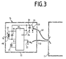
- FIG. 3 shows a unit 14 in which the operating voltage supply is generated in a different way.
- the unit 14 contains a photo element 39 which is connected to the connections 32, 34 of the capacitor 33.
- the photoelement 39 can be illuminated by an optical waveguide 40 which starts from the assembly 11.
- the activation input of the integrated circuit in the unit 14 is connected directly to the connection 37 when the photo element 39 is present.
- the optical waveguide 40 is connected to the input and output circuit 25 via an unspecified connector assembly which contains an optoelectric converter.
- the unit 14 acc. Fig. 3 is inactive when the photo element 39 is not illuminated and the capacitor 33 is discharged. If the photoelement 39 is illuminated, it charges the capacitor 33, as a result of which the integrated circuit contains operating voltage, which at the same time generates the active operating state.
- the received radio telegram is then demodulated and fed to the module 11 via the light transmitter 22 and the optical waveguide 13.
- the antenna 17 with the unit 14 can be set up at a location with a favorable reception field strength for the radio telegrams of the time code. Another advantage of the arrangement is that the unit 14 has its own, self-sufficient power supply.
- the separation of the power supplies of the modules 10, 11 and 12 from the power supply of the unit 14 prevents interference signals from being fed into the modules 10, 11, 12 via operating voltage lines, on the other hand the operating voltage for the modules 10, 11, 12 can fail without losing the operational readiness of the unit 14.
- the photo element 39 can also be briefly so strongly illuminated that the capacitor 33 is charged to the maximum operating voltage of 5.5 V and stores so much energy that the voltage with the unit 14 not active during the period of reception and transmission of the time code drops below 2.5 V.
- optical waveguides 13, 30 and 40 Since only low data rates are transmitted via the optical waveguides 13, 30 and 40, optical waveguides which essentially have a low attenuation are sufficient without the pulse distortion playing a major role.
- the transmission is unidirectional.
- bidirectional transmission on an optical waveguide of the activation signal and the digital time signals is also possible.
- the unit 14 must have a memory which maintains the activation of the circuit for the duration of the time code transmission.
- gate couplers are provided at the ends of the optical fibers.
- the gas density measuring devices 41, 42, 43 are exposed to the same temperature conditions as the gas spaces to be monitored by the high-voltage circuit breakers 2, 3 and 4, since they are installed in the base frames.
- the gas density measuring devices 41, 42 and 43 have the structure shown in FIGS. 4 to 7.
- FIG. 4 shows a gas density measuring device 41 with Bourdon tube 63, pointer 62, scale 61 as well as the pointer drive 64 and with a temperature-sensitive element 65.
- a disk 52 On the axis of the pointer there is a disk 52 with translucent segments 53, as in FIG. 5 shown.
- the gas density can be measured by the compensation effect of the temperature-sensitive member 65.
- the pane 52 can, in a further advantageous embodiment, have zones which reflect light strongly or less strongly or particularly weakly.
- FIG. 6 shows a side view of the measuring system with the disk 52, an optical system 60, which images the light beam transmitted via an optical fiber 64 from a light-emitting diode 59 in a slit onto the disk 52.
- optical fibers 55, 56 and 57 sit behind the disk 52. Their light is conducted in a shielded housing on diodes 58.
- the housing preferably has a first sleeve made of ferromagnetic material and a second sleeve made of an electrically highly conductive material. If a higher accuracy is required, further segments after the gray code are provided for the finer division of the angular range to be measured.
- a measuring cell with a plate spring can also be used.
- the range of the manometer display goes over 270 ° C.
- at least an 8 or 10 bit wide code would be necessary. This would be very expensive for an optical fiber measurement, since 10 return lines would be required.
- the 30 ° range could be represented with a 4-bit code disc, the 60 ° range with a 5-bit code disc and a resolution of 2 °. In this way, the number of light guides that have to be laid from the housing to the respective switch can be reduced.
- the pointer 62 of the Bourdon tube 63 is still present, so that the pressure can also be read on site.
- a light guide can also be used, which branches at its end facing the disk 52 into individual light-guiding elements, the ends of which each face a track of the disk 52.
- the code disk 52 is modified so that it is adapted to the measurement problem. This means that the code segments 53 no longer behave like 4: 2: 1 (3-bit gray code) but define special angular areas of different sizes.
- the limit values at which a message is issued are preferably precisely at the angles at which the bit sequence changes at one point.
- the optical fibers are subject to considerable mechanical alternating stresses during the switching process, which can lead to breakage in the case of glass fibers, it is provided that the optical fibers consist of a highly transparent elastic plastic.
- the optical fibers 54, 55, 56 and 57 are each arranged in an optical fiber cable 44, 45 and 46 in all three gas density measuring devices 41, 42 and 43.
- the light guide cable 44 is laid to the assembly 12 in which the diodes 58 are located.
- the optical fiber cables 45 and 46 are each laid to the modules 10 and 11 in which the associated diodes are arranged.
- the arrangement of the diodes 58 is described in more detail for the assembly 11.
- the diodes 58 are arranged in an input circuit 47 in which the optical fibers 54, 55, 56 and 57 end.
- the diodes assigned to one of the optical fibers 54, 55, 56 and 57 are connected to the input and output circuit 25, which is connected to the parallel bus 26.
- the processor 27 controls the exposure of the optical fiber 54 to light by the diode 57 and determines whether the optical fibers 55, 56 and 57 act on the associated diodes 58 with light via the input and output circuit 25, which contains memories which are not shown.
- the evaluation of the signals emitted by the diodes 58 to the input and output circuit 25 is done by the processor 27, which at the same time detects the times when the signals occur, which are the measured values of the gas density in the associated high-voltage circuit breaker.
- the disk 52 arranged on the shaft of the pointer 62 already provides the gas density measured values in digital form. These gas density measured values are evaluated by the respective assembly 10, 11 and 12, in which the microcomputer circuits containing the processor 27 are arranged as evaluation units. The microcomputer circuits control the reading of the disks 52 at specific times, which can be predetermined by a program.
- the density measurements are assigned to the measurement times.
- the gas density is measured at certain time intervals.
- the time course of the gas pressure can be determined in a specific time period. This time course provides information as to whether the container of the high-voltage switch is tight or has a leak. If the container leaks only slightly, the gas density will gradually decrease.
- the leak rate can be determined from the gas density measurements and the measurement times.
- Certain limit values are specified for the gas density, which must not be undercut if the assigned high-voltage switch is still to work properly.
- the software in the microcomputer circuit compares the measured gas pressure with the limit values, one of which is set so high that the high-voltage switch is still working properly.
- the leak rate On the basis of the determined leak rate, it can be determined in which time span from the time of measurement the first, still uncritical gas density limit value or the further limit values are reached. This period of time is also reported to the personnel responsible for the counter operation. Based on the time period, a check of the high-voltage switch concerned can then be carried out at a time suitable for the execution of the work, for. B. during the weekdays.
- the determination of the leak rate is not affected by occasional interruptions in the operating voltage for the modules 10, 11 and 12.
- the real-time clocks are managed, in particular, as software clocks. However, it is also advantageous to use the clock of a clock generator to run a real-time clock, which is otherwise designed as a software clock.
Landscapes
- Engineering & Computer Science (AREA)
- Power Engineering (AREA)
- Arrangements For Transmission Of Measured Signals (AREA)
Claims (15)
- Procédé pour la surveillance d'appareils de distribution remplis de gaz isolants et d'installations de distribution comprenant au moins un appareil de mesure actionné par la pression du gaz isolant dont les valeurs de mesure sont comparées à au moins une valeur de mesure prédéterminée,
caractérisé en ce que
la densité gazeuse du gaz isolant est saisie par un appareil de mesure de densité (41) qui comprend une cellule de mesure sensible à la pression avec un organe sensible à la température pour générer des valeurs de densité gazeuse indépendantes de la pression et qui est accouplé à un arbre rotatif qui présente un disque (52) muni d'un codage angulaire absolu en particulier dans le code-Gray, disque qui reçoit, par l'intermédiaire d'un guide d'ondes lumineuses (54), de la lumière pour le palpage et qui est dirigé, par la lumière réfléchie ou traversée par l'intermédiaire des guides d'ondes lumineuses (55, 56, 57), à un dispositif d'analyse (11), en ce que des valeurs de mesure sont saisies à des intervalles déterminés sur une base temporelle et sont analysées en fonction de leur courbe temporelle et en ce qu'en présence de modifications temporelles des valeurs de mesure, qui se trouvent au-delà de valeurs limites prédéterminées, un message est généré. - Appareil pour la surveillance d'appareils de distribution remplis de gaz isolants et d'installations de distribution comprenant au moins un appareil de mesure actionné par la pression du gaz isolant dont les valeurs de mesure sont comparées à au moins une valeur de mesure prédéterminée,
caractérisé en ce que
dans l'installation de distribution respective ou dans l'appareil de distribution respectif (2, 3, 4) est disposé au moins un appareil de mesure de densité (41, 42, 43) avec une cellule de mesure sensible à la pression qui est reliée à un organe (65) sensible à la température pour la génération de valeurs de densité gazeuse indépendantes de la pression et est accouplée à un élément d'affichage qui provoque un affichage de densité dérivé d'un angle de rotation, en ce qu'il est prévu, en tant qu'élément d'affichage de l'appareil de mesure (41), un disque (52) muni d'un codage angulaire absolu, en ce que ce disque (52) peut tourner suivant un angle dépendant de la densité, en ce que pour l'affichage, on utilise des rayons lumineux qui sont réfléchis, sont absorbés et sont passés par des segments de code (53), en ce que pour l'alimentation, la collimation, la détection et le transport de signaux, sont utilisés des guides d'ondes lumineuses (54, 55, 56, 57) qui sont guidés dans un coffret (7, 8, 9) qui est blindé contre les champs perturbateurs magnétiques et électromagnétiques et dans lequel est disposé un dispositif d'analyse et une horloge qui peut être synchronisée à des intervalles de temps avec une horloge centrale en temps réel et en ce que dans le dispositif d'analyse sont stockées des valeurs de densité pour la comparaison avec les valeurs de densité mesurées et des valeurs qui déterminent les limites des modifications temporelles. - Dispositif selon la revendication 2,
caractérisé en ce que
l'appareil de mesure de densité gazeuse comprend les caractéristiques suivantes :a) une cellule de mesure, sensible à la pression, est reliée à un organe (65) sensible à la température pour la génération de valeurs de densité gazeuse, dépendantes de la pression, et est accouplée à un élément d'affichage qui provoque un affichage de la densité dérivé d'un angle de rotation,b) l'élément d'affichage de l'appareil de mesure de densité est un disque (52) muni d'un codage angulaire absolu qui est rotatif suivant un angle dépendant de la densité gazeuse,c) pour l'affichage sont utilisés des rayons lumineux qui sont réfléchis différemment par des segments de code ou peuvent passer,d) des guides d'ondes lumineuses (54, 55, 56, 57) sont utilisés pour l'amenée, la collimation et la détection de la lumière et pour le transport de signauxe) les segments de code (53), sur le disque de codage rotatif (52), sont disposés sur des pistes de manière concentrique autour du point de rotation en vue de la réalisation d'un code-Grayf) les segments de code (53) d'une piste, qui selon le code-Gray normal ont la même distance par rapport au centre, qui ont la même longueur et qui sont disposés de manière symétrique par rapport aux autres segments de code de la piste voisine, ont une longueur différente dans un code-Gray modifié,g) les points de départ et de fin des segments de code (53) sont sélectionnés de manière à représenter les valeurs de mesure et de limite essentielles à l'accomplissement d'une opération de mesure et en ce qu'à l'entrée du point de début et de fin du segment de code (53) dans le rayon lumineux, la suite de bit ne se modifie qu'à un endroit lors de la rotation du disque de code (52). - Dispositif selon la revendication 2 ou 3,
caractérisé en ce que
les guides d'ondes lumineuses (13, 30, 37, 38, 44, 45, 46) sont insérés dans des coffrets (7, 8, 9) blindés contre les champs électriques et magnétiques et/ou électromagnétiques, dans lesquels le dispositif d'analyse contient un système de processeur. - Dispositif selon une ou plusieurs des revendications 2 à 4,
caractérisé en ce que
l'appareil de mesure de densité (41) présente une cellule de mesure avec un tube Bourdon. - Dispositif selon une ou plusieurs des revendications 2 à 4,
caractérisé en ce que
l'appareil de mesure de densité (41) présente une cellule de mesure avec un ressort à lame. - Dispositif selon une ou plusieurs des revendications 2 à 6,
caractérisé en ce que
l'appareil de mesure de densité (41) présente une cellule de mesure qui est accouplée à l'élément d'affichage par le biais d'un engrenage. - Dispositif selon une ou plusieurs des revendications précédentes,
caractérisé en ce qu'une antenne (17) est prévue pour la réception de données en temps réel sous forme de télégrammes radio sériels d'une horloge centrale, et en ce que l'antenne (17) est connectée à un lecteur de code relatif au temps présentant un émetteur de lumière qui est connecté, par l'intermédiaire d'une fibre optique (13) à un convertisseur opto-électrique qui est disposé dans le dispositif de mesure et/ou de contrôle et/ou de commande et qui est relié à un dispositif pour le guidage et/ou la synchronisation d'une horloge en temps réel. - Dispositif selon la revendication 8,
caractérisé en ce que
l'horloge centrale est l'horloge radio de l'émetteur DCF 77. - Dispositif selon la revendication 8 ou 9,
caractérisé en ce que
l'antenne (17) et le lecteur de code relatif au temps sont disposés dans un coffret blindé électromagnétiquement (15) qui présente, sur un côté dans le blindage, un évidement (16) pour le passage du rayonnement électromagnétique vers l'antenne (17). - Dispositif selon une ou plusieurs des revendications 2 à 10,
caractérisé en ce que
le lecteur de code relatif au temps est conçu comme un circuit intégré (20) et est destiné à la réception et à la génération de signaux numériques de sortie démodulés d'un télégramme sériel de code relatif au temps avec un générateur de rythme externe à quartz qui est connecté au circuit (20). - Dispositif selon une ou plusieurs des revendications 2 à 11,
caractérisé en ce que
la tension de service pour le lecteur de code relatif au temps est produite par un générateur à piles solaires (17). - Dispositif selon une ou plusieurs des revendications 2 à 4,
caractérisé en ce que
la tension de service pour le lecteur de code relatif au temps est produite par une cellule photo-électrique (39) qui reçoit la lumière par l'intermédiaire d'une fibre optique (40). - Dispositif selon la revendication 13,
caractérisé en ce qu'une extrémité du fibre optique (40) est disposée dans le dispositif de mesure et/ou de commande et/ou de contrôle. - Dispositif selon une ou plusieurs des revendications précédentes,
caractérisé en ce qu'au moins un condensateur du type "Goldcap" est connecté au dispositif pour la génération de la tension de service du lecteur de code relatif au temps.
Applications Claiming Priority (4)
| Application Number | Priority Date | Filing Date | Title |
|---|---|---|---|
| DE19934302076 DE4302076C2 (de) | 1993-01-27 | 1993-01-27 | Dichtemeßgerät |
| DE4302076 | 1993-01-27 | ||
| DE19934319377 DE4319377C2 (de) | 1993-06-11 | 1993-06-11 | Einrichtung zum dezentralen Messen und/oder Überwachen und/oder Steuern an einem Hochspannungsschaltgerät |
| DE4319377 | 1993-06-11 |
Publications (2)
| Publication Number | Publication Date |
|---|---|
| EP0608852A1 EP0608852A1 (fr) | 1994-08-03 |
| EP0608852B1 true EP0608852B1 (fr) | 1997-04-16 |
Family
ID=25922533
Family Applications (1)
| Application Number | Title | Priority Date | Filing Date |
|---|---|---|---|
| EP94101111A Expired - Lifetime EP0608852B1 (fr) | 1993-01-27 | 1994-01-26 | Procédé et dispositif pour la surveillance d'appareils et d'installations de commutations électriques blindées |
Country Status (2)
| Country | Link |
|---|---|
| EP (1) | EP0608852B1 (fr) |
| DE (1) | DE59402406D1 (fr) |
Families Citing this family (2)
| Publication number | Priority date | Publication date | Assignee | Title |
|---|---|---|---|---|
| DE102015008098B4 (de) * | 2015-06-25 | 2023-03-30 | Wika Alexander Wiegand Se & Co. Kg | Messgerät mit gespreizter Messwertausgabe |
| DE102016202853A1 (de) * | 2016-02-24 | 2017-08-24 | Siemens Aktiengesellschaft | Hochspannungs-Leistungsschalter mit einer Anordnung sowie Verfahren zur Energieversorgung des Leistungsschalters |
Family Cites Families (6)
| Publication number | Priority date | Publication date | Assignee | Title |
|---|---|---|---|---|
| US3968691A (en) * | 1974-03-13 | 1976-07-13 | Lynes, Inc. | Environmental condition sensing apparatus |
| US4212198A (en) * | 1979-03-28 | 1980-07-15 | Texaco Inc. | Borehole pressure sensing system |
| GB2122826A (en) * | 1982-06-29 | 1984-01-18 | Nmi Ltd | Displacement measuring gauges |
| DE3428322A1 (de) * | 1984-08-01 | 1986-02-13 | Sachsenwerk, Licht- und Kraft-AG, 8000 München | Verfahren zum ueberwachen von isoliergas in hochspannungsschaltanlagen |
| JPH0738011B2 (ja) * | 1988-05-16 | 1995-04-26 | 株式会社日立製作所 | 高圧電力機器の異常診断システム |
| DE4108588A1 (de) * | 1990-07-26 | 1992-02-06 | Sachsenwerk Ag | Temperaturmesseinrichtung |
-
1994
- 1994-01-26 DE DE59402406T patent/DE59402406D1/de not_active Expired - Fee Related
- 1994-01-26 EP EP94101111A patent/EP0608852B1/fr not_active Expired - Lifetime
Also Published As
| Publication number | Publication date |
|---|---|
| DE59402406D1 (de) | 1997-05-22 |
| EP0608852A1 (fr) | 1994-08-03 |
Similar Documents
| Publication | Publication Date | Title |
|---|---|---|
| DE10305986B4 (de) | Messsystem mit intelligentem Sensorkopf für Mittel- oder Hochspannungsanlagen oder im Bergbau | |
| DE60025927T2 (de) | Teilentladungsüberwachungssystem für transformatoren | |
| EP0249815B1 (fr) | Dispositif pour la détection d'arcs de défaut | |
| DE60225246T2 (de) | Überwachungssystem | |
| EP1574822A1 (fr) | Dispositif de controle a distance de l'etat de lignes aeriennes de transport d'electricite (variantes) | |
| DE3044944A1 (de) | Feueralarmsystem | |
| DE3030632A1 (de) | Telemetriesystem | |
| EP0878043B1 (fr) | Procede de determination de la position d'un appareil de commutation | |
| WO2007118436A1 (fr) | Procédé de contrôle de la qualité de l'énergie électrique dans un réseau d'alimentation en énergie électrique, appareil de terrain de contrôle de la qualité de courant et système de contrôle de la qualité de courant | |
| DE60307639T2 (de) | Verfahren und system zur übermittlung eines informationssignals über ein stromleitungskabel | |
| DE4319377C2 (de) | Einrichtung zum dezentralen Messen und/oder Überwachen und/oder Steuern an einem Hochspannungsschaltgerät | |
| EP0608852B1 (fr) | Procédé et dispositif pour la surveillance d'appareils et d'installations de commutations électriques blindées | |
| WO1994021504A1 (fr) | Installation d'avertissement optique de personnel travaillant sur la voie | |
| EP0878041B1 (fr) | Dispositif blinde | |
| DE10037911A1 (de) | Vorrichtung zum Messen/Bestimmen einer physikalischen Grösse eines Mediums | |
| EP2508839B1 (fr) | Dispositif de mesure doté d'une commutation d'émission pour la transmission sans fil d'un signal de mesure | |
| DE4443646C2 (de) | Einrichtung zur Messung und Auswertung der Temperatur an oder in einem elektrischen Schaltgerät | |
| DE4024843A1 (de) | Sensoranordnung | |
| DE19543363C2 (de) | Meßwandleranordnung | |
| DE69226803T2 (de) | Positionsmeldevorrichtung eines beweglichen Gliedes | |
| EP0355559A1 (fr) | Circuit de surveillance d'un compteur d'électricité électronique | |
| DE19546215C1 (de) | Schaltstellungsanzeigesystem | |
| DE4302076C2 (de) | Dichtemeßgerät | |
| EP2639603A2 (fr) | Dispositif de détection | |
| DE19545999A1 (de) | Inkrementaler Stellungsgeber |
Legal Events
| Date | Code | Title | Description |
|---|---|---|---|
| PUAI | Public reference made under article 153(3) epc to a published international application that has entered the european phase |
Free format text: ORIGINAL CODE: 0009012 |
|
| AK | Designated contracting states |
Kind code of ref document: A1 Designated state(s): CH DE FR LI SE |
|
| 17P | Request for examination filed |
Effective date: 19941227 |
|
| 17Q | First examination report despatched |
Effective date: 19960124 |
|
| GRAG | Despatch of communication of intention to grant |
Free format text: ORIGINAL CODE: EPIDOS AGRA |
|
| GRAH | Despatch of communication of intention to grant a patent |
Free format text: ORIGINAL CODE: EPIDOS IGRA |
|
| GRAH | Despatch of communication of intention to grant a patent |
Free format text: ORIGINAL CODE: EPIDOS IGRA |
|
| GRAA | (expected) grant |
Free format text: ORIGINAL CODE: 0009210 |
|
| AK | Designated contracting states |
Kind code of ref document: B1 Designated state(s): CH DE FR LI SE |
|
| REG | Reference to a national code |
Ref country code: CH Ref legal event code: NV Representative=s name: KIRKER & CIE SA Ref country code: CH Ref legal event code: EP |
|
| RAP2 | Party data changed (patent owner data changed or rights of a patent transferred) |
Owner name: AEG ENERGIETECHNIK GMBH Owner name: DAIMLER-BENZ AKTIENGESELLSCHAFT |
|
| REF | Corresponds to: |
Ref document number: 59402406 Country of ref document: DE Date of ref document: 19970522 |
|
| ET | Fr: translation filed | ||
| PLBE | No opposition filed within time limit |
Free format text: ORIGINAL CODE: 0009261 |
|
| STAA | Information on the status of an ep patent application or granted ep patent |
Free format text: STATUS: NO OPPOSITION FILED WITHIN TIME LIMIT |
|
| 26N | No opposition filed | ||
| REG | Reference to a national code |
Ref country code: CH Ref legal event code: PFA Free format text: AEG ENERGIETECHNIK GMBH;DAIMLER-BENZ AKTIENGESELLSCHAFT TRANSFER- AEG ENERGIETECHNIK GMBH;DAIMLERCHRYSLER AG |
|
| REG | Reference to a national code |
Ref country code: FR Ref legal event code: TQ |
|
| REG | Reference to a national code |
Ref country code: CH Ref legal event code: PUEA Free format text: AEG ENERGIETECHNIK GMBH;DAIMLERCHRYSLER AG TRANSFER- AEG ENERGIETECHNIK GMBH Ref country code: CH Ref legal event code: PFA Free format text: AEG ENERGIETECHNIK GMBH TRANSFER- ALSTOM ENERGIETECHNIK GMBH |
|
| REG | Reference to a national code |
Ref country code: FR Ref legal event code: TQ Ref country code: FR Ref legal event code: CD |
|
| REG | Reference to a national code |
Ref country code: CH Ref legal event code: PFA Owner name: ALSTOM ENERGIETECHNIK GMBH Free format text: ALSTOM ENERGIETECHNIK GMBH#LYONER STRASSE 44-48#60528 FRANKFURT (DE) -TRANSFER TO- ALSTOM ENERGIETECHNIK GMBH#LYONER STRASSE 44-48#60528 FRANKFURT AM MAIN (DE) |
|
| REG | Reference to a national code |
Ref country code: CH Ref legal event code: PFA Owner name: AREVA ENERGIETECHNIK GMBH Free format text: ALSTOM ENERGIETECHNIK GMBH#LYONER STRASSE 44-48#60528 FRANKFURT AM MAIN (DE) -TRANSFER TO- AREVA ENERGIETECHNIK GMBH#LYONER STRASSE 44-48#60528 FRANKFURT AM MAIN (DE) |
|
| REG | Reference to a national code |
Ref country code: FR Ref legal event code: CD |
|
| PGFP | Annual fee paid to national office [announced via postgrant information from national office to epo] |
Ref country code: DE Payment date: 20090325 Year of fee payment: 16 |
|
| PGFP | Annual fee paid to national office [announced via postgrant information from national office to epo] |
Ref country code: CH Payment date: 20090126 Year of fee payment: 16 |
|
| PGFP | Annual fee paid to national office [announced via postgrant information from national office to epo] |
Ref country code: SE Payment date: 20090126 Year of fee payment: 16 |
|
| PGFP | Annual fee paid to national office [announced via postgrant information from national office to epo] |
Ref country code: FR Payment date: 20090120 Year of fee payment: 16 |
|
| REG | Reference to a national code |
Ref country code: CH Ref legal event code: PL |
|
| EUG | Se: european patent has lapsed | ||
| REG | Reference to a national code |
Ref country code: FR Ref legal event code: ST Effective date: 20100930 |
|
| PG25 | Lapsed in a contracting state [announced via postgrant information from national office to epo] |
Ref country code: LI Free format text: LAPSE BECAUSE OF NON-PAYMENT OF DUE FEES Effective date: 20100131 Ref country code: FR Free format text: LAPSE BECAUSE OF NON-PAYMENT OF DUE FEES Effective date: 20100201 Ref country code: CH Free format text: LAPSE BECAUSE OF NON-PAYMENT OF DUE FEES Effective date: 20100131 |
|
| PG25 | Lapsed in a contracting state [announced via postgrant information from national office to epo] |
Ref country code: DE Free format text: LAPSE BECAUSE OF NON-PAYMENT OF DUE FEES Effective date: 20100803 |
|
| PG25 | Lapsed in a contracting state [announced via postgrant information from national office to epo] |
Ref country code: SE Free format text: LAPSE BECAUSE OF NON-PAYMENT OF DUE FEES Effective date: 20100127 |