EP0608978A1 - Dispositif d'avertissement de coups de béliers des roues dentées - Google Patents
Dispositif d'avertissement de coups de béliers des roues dentées Download PDFInfo
- Publication number
- EP0608978A1 EP0608978A1 EP94300149A EP94300149A EP0608978A1 EP 0608978 A1 EP0608978 A1 EP 0608978A1 EP 94300149 A EP94300149 A EP 94300149A EP 94300149 A EP94300149 A EP 94300149A EP 0608978 A1 EP0608978 A1 EP 0608978A1
- Authority
- EP
- European Patent Office
- Prior art keywords
- indicative
- clutch
- engaged
- transmission
- jaw
- Prior art date
- Legal status (The legal status is an assumption and is not a legal conclusion. Google has not performed a legal analysis and makes no representation as to the accuracy of the status listed.)
- Withdrawn
Links
Images


Classifications
-
- F—MECHANICAL ENGINEERING; LIGHTING; HEATING; WEAPONS; BLASTING
- F16—ENGINEERING ELEMENTS AND UNITS; GENERAL MEASURES FOR PRODUCING AND MAINTAINING EFFECTIVE FUNCTIONING OF MACHINES OR INSTALLATIONS; THERMAL INSULATION IN GENERAL
- F16H—GEARING
- F16H61/00—Control functions within control units of change-speed- or reversing-gearings for conveying rotary motion ; Control of exclusively fluid gearing, friction gearing, gearings with endless flexible members or other particular types of gearing
- F16H61/04—Smoothing ratio shift
- F16H61/0403—Synchronisation before shifting
-
- F—MECHANICAL ENGINEERING; LIGHTING; HEATING; WEAPONS; BLASTING
- F16—ENGINEERING ELEMENTS AND UNITS; GENERAL MEASURES FOR PRODUCING AND MAINTAINING EFFECTIVE FUNCTIONING OF MACHINES OR INSTALLATIONS; THERMAL INSULATION IN GENERAL
- F16H—GEARING
- F16H61/00—Control functions within control units of change-speed- or reversing-gearings for conveying rotary motion ; Control of exclusively fluid gearing, friction gearing, gearings with endless flexible members or other particular types of gearing
- F16H61/18—Preventing unintentional or unsafe shift, e.g. preventing manual shift from highest gear to reverse gear
-
- B—PERFORMING OPERATIONS; TRANSPORTING
- B60—VEHICLES IN GENERAL
- B60W—CONJOINT CONTROL OF VEHICLE SUB-UNITS OF DIFFERENT TYPE OR DIFFERENT FUNCTION; CONTROL SYSTEMS SPECIALLY ADAPTED FOR HYBRID VEHICLES; ROAD VEHICLE DRIVE CONTROL SYSTEMS FOR PURPOSES NOT RELATED TO THE CONTROL OF A PARTICULAR SUB-UNIT
- B60W30/00—Purposes of road vehicle drive control systems not related to the control of a particular sub-unit, e.g. of systems using conjoint control of vehicle sub-units
- B60W30/18—Propelling the vehicle
- B60W30/18009—Propelling the vehicle related to particular drive situations
- B60W30/18027—Drive off, accelerating from standstill
-
- F—MECHANICAL ENGINEERING; LIGHTING; HEATING; WEAPONS; BLASTING
- F16—ENGINEERING ELEMENTS AND UNITS; GENERAL MEASURES FOR PRODUCING AND MAINTAINING EFFECTIVE FUNCTIONING OF MACHINES OR INSTALLATIONS; THERMAL INSULATION IN GENERAL
- F16H—GEARING
- F16H61/00—Control functions within control units of change-speed- or reversing-gearings for conveying rotary motion ; Control of exclusively fluid gearing, friction gearing, gearings with endless flexible members or other particular types of gearing
- F16H61/12—Detecting malfunction or potential malfunction, e.g. fail safe ; Circumventing or fixing failures
-
- B—PERFORMING OPERATIONS; TRANSPORTING
- B60—VEHICLES IN GENERAL
- B60W—CONJOINT CONTROL OF VEHICLE SUB-UNITS OF DIFFERENT TYPE OR DIFFERENT FUNCTION; CONTROL SYSTEMS SPECIALLY ADAPTED FOR HYBRID VEHICLES; ROAD VEHICLE DRIVE CONTROL SYSTEMS FOR PURPOSES NOT RELATED TO THE CONTROL OF A PARTICULAR SUB-UNIT
- B60W50/00—Details of control systems for road vehicle drive control not related to the control of a particular sub-unit, e.g. process diagnostic or vehicle driver interfaces
- B60W50/08—Interaction between the driver and the control system
- B60W50/14—Means for informing the driver, warning the driver or prompting a driver intervention
- B60W2050/143—Alarm means
-
- B—PERFORMING OPERATIONS; TRANSPORTING
- B60—VEHICLES IN GENERAL
- B60W—CONJOINT CONTROL OF VEHICLE SUB-UNITS OF DIFFERENT TYPE OR DIFFERENT FUNCTION; CONTROL SYSTEMS SPECIALLY ADAPTED FOR HYBRID VEHICLES; ROAD VEHICLE DRIVE CONTROL SYSTEMS FOR PURPOSES NOT RELATED TO THE CONTROL OF A PARTICULAR SUB-UNIT
- B60W2540/00—Input parameters relating to occupants
- B60W2540/14—Clutch pedal position
-
- F—MECHANICAL ENGINEERING; LIGHTING; HEATING; WEAPONS; BLASTING
- F16—ENGINEERING ELEMENTS AND UNITS; GENERAL MEASURES FOR PRODUCING AND MAINTAINING EFFECTIVE FUNCTIONING OF MACHINES OR INSTALLATIONS; THERMAL INSULATION IN GENERAL
- F16H—GEARING
- F16H61/00—Control functions within control units of change-speed- or reversing-gearings for conveying rotary motion ; Control of exclusively fluid gearing, friction gearing, gearings with endless flexible members or other particular types of gearing
- F16H61/04—Smoothing ratio shift
- F16H2061/047—Smoothing ratio shift by preventing or solving a tooth butt situation upon engagement failure due to misalignment of teeth
-
- F—MECHANICAL ENGINEERING; LIGHTING; HEATING; WEAPONS; BLASTING
- F16—ENGINEERING ELEMENTS AND UNITS; GENERAL MEASURES FOR PRODUCING AND MAINTAINING EFFECTIVE FUNCTIONING OF MACHINES OR INSTALLATIONS; THERMAL INSULATION IN GENERAL
- F16H—GEARING
- F16H61/00—Control functions within control units of change-speed- or reversing-gearings for conveying rotary motion ; Control of exclusively fluid gearing, friction gearing, gearings with endless flexible members or other particular types of gearing
- F16H61/02—Control functions within control units of change-speed- or reversing-gearings for conveying rotary motion ; Control of exclusively fluid gearing, friction gearing, gearings with endless flexible members or other particular types of gearing characterised by the signals used
- F16H61/0202—Control functions within control units of change-speed- or reversing-gearings for conveying rotary motion ; Control of exclusively fluid gearing, friction gearing, gearings with endless flexible members or other particular types of gearing characterised by the signals used the signals being electric
- F16H61/0248—Control units where shifting is directly initiated by the driver, e.g. semi-automatic transmissions
-
- F—MECHANICAL ENGINEERING; LIGHTING; HEATING; WEAPONS; BLASTING
- F16—ENGINEERING ELEMENTS AND UNITS; GENERAL MEASURES FOR PRODUCING AND MAINTAINING EFFECTIVE FUNCTIONING OF MACHINES OR INSTALLATIONS; THERMAL INSULATION IN GENERAL
- F16H—GEARING
- F16H61/00—Control functions within control units of change-speed- or reversing-gearings for conveying rotary motion ; Control of exclusively fluid gearing, friction gearing, gearings with endless flexible members or other particular types of gearing
- F16H61/68—Control functions within control units of change-speed- or reversing-gearings for conveying rotary motion ; Control of exclusively fluid gearing, friction gearing, gearings with endless flexible members or other particular types of gearing specially adapted for stepped gearings
- F16H61/682—Control functions within control units of change-speed- or reversing-gearings for conveying rotary motion ; Control of exclusively fluid gearing, friction gearing, gearings with endless flexible members or other particular types of gearing specially adapted for stepped gearings with interruption of drive
-
- F—MECHANICAL ENGINEERING; LIGHTING; HEATING; WEAPONS; BLASTING
- F16—ENGINEERING ELEMENTS AND UNITS; GENERAL MEASURES FOR PRODUCING AND MAINTAINING EFFECTIVE FUNCTIONING OF MACHINES OR INSTALLATIONS; THERMAL INSULATION IN GENERAL
- F16H—GEARING
- F16H61/00—Control functions within control units of change-speed- or reversing-gearings for conveying rotary motion ; Control of exclusively fluid gearing, friction gearing, gearings with endless flexible members or other particular types of gearing
- F16H61/70—Control functions within control units of change-speed- or reversing-gearings for conveying rotary motion ; Control of exclusively fluid gearing, friction gearing, gearings with endless flexible members or other particular types of gearing specially adapted for change-speed gearing in group arrangement, i.e. with separate change-speed gear trains arranged in series, e.g. range or overdrive-type gearing arrangements
- F16H61/702—Control functions within control units of change-speed- or reversing-gearings for conveying rotary motion ; Control of exclusively fluid gearing, friction gearing, gearings with endless flexible members or other particular types of gearing specially adapted for change-speed gearing in group arrangement, i.e. with separate change-speed gear trains arranged in series, e.g. range or overdrive-type gearing arrangements using electric or electrohydraulic control means
-
- F—MECHANICAL ENGINEERING; LIGHTING; HEATING; WEAPONS; BLASTING
- F16—ENGINEERING ELEMENTS AND UNITS; GENERAL MEASURES FOR PRODUCING AND MAINTAINING EFFECTIVE FUNCTIONING OF MACHINES OR INSTALLATIONS; THERMAL INSULATION IN GENERAL
- F16H—GEARING
- F16H63/00—Control outputs from the control unit to change-speed- or reversing-gearings for conveying rotary motion or to other devices than the final output mechanism
- F16H63/40—Control outputs from the control unit to change-speed- or reversing-gearings for conveying rotary motion or to other devices than the final output mechanism comprising signals other than signals for actuating the final output mechanisms
-
- Y—GENERAL TAGGING OF NEW TECHNOLOGICAL DEVELOPMENTS; GENERAL TAGGING OF CROSS-SECTIONAL TECHNOLOGIES SPANNING OVER SEVERAL SECTIONS OF THE IPC; TECHNICAL SUBJECTS COVERED BY FORMER USPC CROSS-REFERENCE ART COLLECTIONS [XRACs] AND DIGESTS
- Y10—TECHNICAL SUBJECTS COVERED BY FORMER USPC
- Y10T—TECHNICAL SUBJECTS COVERED BY FORMER US CLASSIFICATION
- Y10T74/00—Machine element or mechanism
- Y10T74/19—Gearing
- Y10T74/19167—In series plural interchangeably locked nonplanetary units
-
- Y—GENERAL TAGGING OF NEW TECHNOLOGICAL DEVELOPMENTS; GENERAL TAGGING OF CROSS-SECTIONAL TECHNOLOGIES SPANNING OVER SEVERAL SECTIONS OF THE IPC; TECHNICAL SUBJECTS COVERED BY FORMER USPC CROSS-REFERENCE ART COLLECTIONS [XRACs] AND DIGESTS
- Y10—TECHNICAL SUBJECTS COVERED BY FORMER USPC
- Y10T—TECHNICAL SUBJECTS COVERED BY FORMER US CLASSIFICATION
- Y10T74/00—Machine element or mechanism
- Y10T74/19—Gearing
- Y10T74/19219—Interchangeably locked
- Y10T74/19251—Control mechanism
- Y10T74/19256—Automatic
- Y10T74/1926—Speed responsive
Definitions
- the present invention relates to a control system/method for controlling start from stop operations of a semi-automated mechanical transmission system of the type automatically implementing selected gear changes but requiring manual operation of the vehicle master clutch during start from stop operations.
- the drawbacks of the prior art are minimized or overcome by the provision of a control system for a semi-automatic mechanical transmission of the type automatically implementing selected shifts and requiring manual master clutch start from stop operation which will sense a gear butt condition and will then warn the vehicle operator thereof so that corrective action may be taken.
- the above is accomplished by sensing when a start gear engagement is initiated or commanded and sensing if, after a predetermined period of time, engagement of the start gear is not accomplished. Such sensing may involve sensing movement of a jaw clutch from its neutral position toward its engaged position but not sensing arrival at the engaged position and/or not sensing transmission input shaft and output shaft speeds indicative of jaw clutch engagement. If a gear butt condition is sensed, the operator is notified of the condition so that appropriate corrective actions, such as momentarily feathering the master clutch to knock the jaw clutch off its butting condition, may be manually initiated.
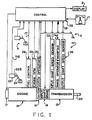
- Figure 1 is a symbolic illustration of a semi-automatic mechanical transmission system.
- Figure 2 is a symbolic illustration of control members and sensors of the system illustrated in Figure 1.
- FIGS 3 and 3B illustrate the control and display console of the system illustrated in Figure 1.
- Figure 4 is a symbolic illustration of a "4x3" twelve speed compound splitter type semi-blocked transmission.
- Figure 5 illustrates the typical shift pattern for the transmission of Figure 4.
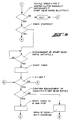
- FIG. 6 is a schematic illustration, in flow chart format, of the control logic of the present invention.
- compound transmission is used to designate a change speed transmission having a main transmission portion and an auxiliary transmission portion connected in series whereby the selected gear reduction in the main transmission portion may be compounded by further selected gear reduction in the auxiliary transmission portion.
- splitter type compound transmission as used herein will designate a compound transmission wherein the auxiliary transmission is used to provide various selectable steps for subdivisions of the gear ratio selected in the main transmission portion.
- the main transmission section is typically provided with relatively wide steps which are split or subdivided by the auxiliary section.
- upshift as used herein, shall mean the shifting from a lower speed gear ratio into a higher speed gear ratio.
- locked transmission or "blocked transmission section” shall designate a change gear constant mesh transmission or transmission section, wherein a selected one of a plurality of axially moveable gears is nonrotatably coupled to a shaft as a result of axial movement of the selected gear from the neutral to the engaged position thereof, and by means of a resiliently biased positive clutch and a blocker is utilized to prevent such engagement until the members of the positive clutch are at substantially synchronous rotation, such synchronous condition achieved by manual and/or automatic manipulation of the transmission input and/or output shafts to cause a crossing of synchronous condition therebetween, but not typically achieved by frictional contact of the selected clutch members sufficient to cause one of the clutch members, and the apparatus associated therewith, to rotate with the other clutch member.
- Blocked transmissions and/or transmission sections are illustrated in United States Patent Nos. 3,799,002; 3,924,484; 4,192,196 and 4,440,037, the disclosures of all of which are hereby incorporated by reference.
- the semi-automatic control system of the present invention is particularly advantageously applied to a splitter type compound transmission of the type having a non-synchronized, non-blocked main transmission section connected in series with an auxiliary section of the blocked splitter type.
- Such transmissions are known in the prior art and are referred to as "semi-blocked" transmissions, and are described and illustrated in U.S. Patents Nos. 4,735,109 and 4,736,643, the disclosures of which are hereby incorporated by reference.
- the position of a driver-operated throttle 24 is sensed at sensor 22 and a signal indicative thereof (THD) fed to a central processing unit 38, which also receives inputs relative to engine speed from sensor 28 and/or transmission input shaft speed from sensor 32, transmission output shaft speed from sensor 36, and positive or negative actuations of the driver's gear shift lever 1, or "joy stick,” to be described in greater detail below.
- TDD signal indicative thereof
- central processing unit 38 which also receives inputs relative to engine speed from sensor 28 and/or transmission input shaft speed from sensor 32, transmission output shaft speed from sensor 36, and positive or negative actuations of the driver's gear shift lever 1, or "joy stick,” to be described in greater detail below.
- engine speed is an indication of transmission input shaft speed, and visa versa, especially if clutch 16 is nonslippingly engaged, while transmission output shaft speed is an indication of vehicle speed.
- throttle position sensor assembly 22 for sensing the operators setting of a throttle pedal 24, or the like, and providing a signal proportional to, or at least indicative of, the monitored setting, and so called "remote fuel control" or “fly by wire” systems utilizing same, are known in the prior art and illustrated in the United States Patent Nos. 4,250,845; 4,305,359; 4,319,658 and 4,461,254, the disclosures of which are hereby incorporated by reference.
- Control logic circuits, sensors, and actuators for the transmission system 10 as disclosed in Figures 1 and 2 may be as disclosed in United States Patent No. 4,361,060 and 4,595,986, the disclosures of which are hereby incorporated by reference.
- central processing unit 38 receives inputs, processes same in accordance with predetermined logic rules, and provides command output signals to pneumatic and/or electrical actuators for control of an exhaust brake 17 and/or an input shaft brake 18 for rapid upshifts, and automatic fuel control 26 to "blip" the supply of fuel to the engine 14 to achieve rapid synchronous rotation preparatory to a downshift, clutch control via operator 30, and ratio shifting via transmission operator 34.
- the central processing unit also sends command output signals to the display 2 to be described in greater detail below.
- the automatic/semi-automatic transmission system 10 additionally comprises a usual foot operated manual clutch control 3 intended for use only for start from rest and/or low speed creeping maneuvering situations.
- the control 38 receives signals indicative of manual clutch control 3 position and of actuation of the vehicle brakes 4.
- the automatic/semi-automatic mechanical transmission system 10 also includes sources of electric and/or pneumatic power (not illustrated).
- blip designates a temporary increase in the supply of fuel to the engine 14, while the term “dip” means a momentary decrease in supply of fuel to the engine.
- dip means a momentary decrease in supply of fuel to the engine.
- the terms blip and dip are usually associated with automatic controller 38 commanded increases and decreases, respectively, of the supply of fuel to the engine independent of the operator selected position of manual throttle pedal 24.
- the central processing unit 38 may be contained in a box or housing 38A, which housing carries the display panel 2 having an upshift indicator display 2', a downshift indicator display 2'', and a currently engaged gear ratio display 2''', the shift select lever 1, an optional reverse enable button 1A, as well as a central processing unit electronic circuitry 38B.
- the display 2 includes upshift indicator section 2', downshift indicator section 2'' and currently engaged gear ratio indicator section 2'''.
- the currently engaged gear ratio display section 2''' is presently displaying a "6" indicating that the vehicle transmission is operating in sixth (6th) gear.
- the upshift display section 2' has three lines indicating the maximum number of permissible consecutive upshifts permitted according to the sensed input parameters, such as sensed engine or input shaft speed and sensed output shaft speed as processed according to the predetermined logic rules or program. In the present situation, the three lines indicate that a single, a double or a triple upshift is permissible.
- the driver may select a permissible shift directly to either seventh (7th), eighth (8th) or ninth (9th) speed.
- the downshift display 2'' section has two lines indicating the maximum number of permissible consecutive downshifts permitted according to the sensed parameters as processed by the predetermined logic or program. In the present situation, the two lines in display 2' indicate that the transmission may be permissibly downshifted to either fifth (5th) or to fourth (4th) gear.
- the permissibility of a possible upshift or downshift is determined by comparing the expected engine speed at the completion of such an upshift or downshift, assuming a substantially constant vehicle speed and fully engaged master clutch, to a fixed range of maximum and minimum permissible engine speeds.
- the central processing unit 38 will not issue command signals to execute a selected impermissible ratio change.
- a central processing unit will execute the closest permissible ratio change to that selected by the operator.
- the central processing unit 38 will not be executed by the central processing unit 38 as being impermissible.
- the central processing unit 38 will issue command output signals for a double downshift from sixth gear to fourth gear. Not only is an impermissible ratio change refused, but the driver will usually have been advised already by display 2 that the ratio should never have been attempted or selected.
- the display 2 provides an indication to the operator what upshifts and downshifts are permitable and as to which upshifts and downshifts are impermissible. Should the driver not heed the warning, the central processing unit 38 will not generate impermissible shift command even though synchronization of the mechanical jaw clutch elements could be obtained by the system.
- the declutching of the master clutch 16 and synchronizing of the selected jaw clutch members associated with the selected gear ratio is achieved automatically and rapidly due to automatic throttle and clutch control and braking of the input shaft and/or the engine.
- the control system is semi-automatic and the driver must exercise his discretion as to when to up or downshift, and as to how many gear ratios to up or downshift, but is not called upon to coordinate gear lever, throttle pedal and clutch actuation. Once the driver has selected a permitted gear ratio, the throttle is blipped to achieve necessary synchronization during a downshift, or dipped for achieving necessary synchronization during an upshift, all of which is done automatically for the driver by the central processing unit 38.
- the reverse mode of operation may be achieved only from the neutral at rest position and then is achieved by moving control lever 1 backwardly from the currently engaged neutral position.
- a reverse button 1A may be provided which button must be depressed prior to the central processing unit interpreting a backward movement of the control lever 1 when in the neutral position as a request for reverse operation.
- control logic When the vehicle comes to rest from above a predetermined vehicle speed, and the operator manually disengages the vehicle master clutch, the control logic will interpret a single displacement of lever 1 in the downshift direction as an operator selection of a direct shift into a predetermined start gear ratio and will issue the necessary command output signals to implement such a shift.
- transmission 1 2 is a multi-speed transmission having at least five, preferably nine or more, selectable forward ratios.
- the structure of a twelve forward speed splitter type transmission 12, and of the blocked jaw clutch members utilized in the auxiliary transmission section of transmission 12, is known in the prior art and may be appreciated in greater detail by reference to above mentioned United States Patent Nos. 3,799,002 and 4,735,109.
- the transmission includes an input shaft 218 supported adjacent its rearward end by a bearing 220 and is provided with an input gear 222 nonrotatably connected thereto, as by splines.
- the input gear 222 simultaneously drives a plurality of main section countershafts at equal speeds.
- the transmission is provided with two main section countershafts, 224 and 226, disposed on diametrically opposite sides of the mainshaft 228, which mainshaft is coaxially aligned with the input shaft 218 and is provided with a pilot portion 230 on its forward end rotatably received within and supported by the rearward end of the input shaft 218.
- the input shaft 218 is normally driven in one direction only by a prime mover, such as a throttle controlled Diesel engine E through a selectively operated, normally engaged, friction master clutch C.
- Clutch C may be selectively disengaged by use of pedal P as is known in the prior art.
- Clutch C may have a known clutch-brake associated therewith.
- Each of the main section countershafts 224 and 226 is provided with an identical grouping of countershaft gears, such as the pair of gears 236, of identical size and number of teeth and disposed on diametrically opposite sides of the mainshaft 228.
- countershaft gears 242 and 244 may be defined by involute splines formed directly on the main section countershafts.
- a plurality of main section mainshaft drive gears 246, 248, 250 and 252 surround the mainshaft 228 and are selectably clutchable thereto, one at a time, by sliding clutch collars as is well known in the art.
- the main section mainshaft gears 246, 248 and 250 encircle the mainshaft 228, are in continuous meshing engagement with, and are floatingly supported by the diametrically opposite pairs of countershaft gears, 238, 240 and 242, respectively, which mounting means and the special advantages resulting therefrom are explained in greater detail in U.S. Pats. Nos. 3,105,395 and 3,335,616, the disclosures of which are hereby incorporated by reference.
- the mainshaft gear 252 is the reverse gear and is in continuous meshing engagement with a pair of countershaft gears 244 by means of conventional intermediate idler gears (not shown).
- the forwardmost countershaft gears 236 are continually meshed with and driven by the input gear 222 for causing simultaneous rotation of the countershafts 224 and 226 whenever the input shaft is rotatably driven.
- Main section mainshaft gears 246, 248, 250 and 252; and main section countershaft gears 236, 238, 240, 242 and 244, and the idler gears, are all constantly meshed with and driven by the input gear 222 and thus, in combination, form the input gearing of the transmission 12.
- various abutment rings 254 are provided to axially fix the main section mainshaft gears relative to mainshaft 228.
- Sliding clutch collars 256, 258 and 260 are splined to mainshaft 228 for axial movement relative thereto and rotation therewith as is well known in the art.
- Sliding clutch 256 is axially slidable by means of shift fork 262 to clutch gear 252 to the mainshaft.
- Sliding clutch 258 is axially slidable by means of shift fork 264 to clutch either gear 250 or 248 to the mainshaft.
- Sliding clutch 260 is axially slidable by means of shift fork 264 to clutch gear 246 to the mainshaft or to clutch the input gear 222 (and thus the input shaft 218) to the mainshaft.
- Shift forks 262, 264 and 266 are attached to shift bars or rails of a known shift bar housing assembly.
- the mainshaft 228 extends thereinto and is coaxially arranged with and piloted into an output shaft 274 which is in turn supported within the housing 216 by suitable bearings generally indicated at 276.
- Said auxiliary section further includes a plurality of auxiliary section countershafts 278 and 280 each having an identical grouping of countershaft gears 284, 286 and 288 therein.
- mainshaft section countershafts, 224 and 226, are displaced about 90° from the auxiliary section countershafts.
- Main section countershafts are supported in housing 216 by bearings 290 and 292 while auxiliary section countershafts, 278 and 280, are supported in housing 216 by bearings 294 and 296.
- auxiliary section mainshaft gears 308 and 310, encircle the mainshaft 228 and are constantly meshed with and floatingly supported by the auxiliary countershaft gear pairs 284 and 286, respectively.
- Output gear 312 is splined to output shaft 274 for axial movement relative thereto and rotational movement therewith.
- Output gear 312 is constantly meshed with auxiliary countershaft gear pair 288.
- Resiliently biased clutch members 316, 318 and 320 are splined to mainshaft 228 and, in combination with blockers (not shown) provide resilient, blocked clutching apparatus of the type described in above-mentioned U.S. Pat. Nos. 3,799,002, 3,921,469 and 3,924,484 for selectively clutching gears 308, 310 and 312, respectively, one at a time, to mainshaft 228.
- Clutch 316 is biased axially by spring 330 and limited in its axial movement by positive stop 334.
- Clutch members 318 and 320 are biased axially apart by spring 138 surrounding the mainshaft and limited in axial movement by stops 338 and 340.
- Gear 312 is axially moved by shift fork 342 and gears 308 and 310 are joined for joint axial movement and independent rotation by ring 346 and are axially movable by shift fork 348.
- Gears 308, 310 or 312 are selectively engaged, one at a time, to mainshaft 228.
- engagement of gear 312 to the mainshaft 228 is effective to couple mainshaft 228 directly to the output shaft 274.
- the various jaw clutches, 256, 258 and 260 have a first nondisplaced axial position as shown in Figure 4 and at least one second fully displaced axial position wherein the selected gear is rotationally coupled to the mainshaft 228.
- the axial position of the jaw clutches are usually monitored by monitoring shift fork/shift rail position.
- Such sensors are well known in the prior art as may be seen by reference to U.S. Patents Nos. 4,676,115 and 4,945,484, the disclosures of which are incorporated by reference.
- T REF a reference time
- sensing conditions indicate of start gear ratio engagement (such as sensing full axial displacement of the associated jaw clutch/shift fork/shift rail)
- the warning will continue for so long as conditions indicative of a gear butt continue to exist and the warning will be displayed on the display 2, such as by flashing the number of the engaging start gear in section 2''' until the gear is sensed as fully engaged.
- the present invention provides a control system/method for controlling the start from stop operations of semi-automated mechanical transmission systems of the type automatically implementing selected gear ratio changes and requiring manual operation of the vehicle master clutch for start from stop operations, which will sense conditions indicative of gear butt conditions during a start from stop operation and will warn the vehicle operator thereof.
Landscapes
- Engineering & Computer Science (AREA)
- General Engineering & Computer Science (AREA)
- Mechanical Engineering (AREA)
- Automation & Control Theory (AREA)
- Transportation (AREA)
- Control Of Transmission Device (AREA)
- Control Of Driving Devices And Active Controlling Of Vehicle (AREA)
Applications Claiming Priority (2)
| Application Number | Priority Date | Filing Date | Title |
|---|---|---|---|
| GB9301294 | 1993-01-23 | ||
| GB939301294A GB9301294D0 (en) | 1993-01-23 | 1993-01-23 | Gear butt warning |
Publications (1)
| Publication Number | Publication Date |
|---|---|
| EP0608978A1 true EP0608978A1 (fr) | 1994-08-03 |
Family
ID=10729175
Family Applications (1)
| Application Number | Title | Priority Date | Filing Date |
|---|---|---|---|
| EP94300149A Withdrawn EP0608978A1 (fr) | 1993-01-23 | 1994-01-10 | Dispositif d'avertissement de coups de béliers des roues dentées |
Country Status (8)
| Country | Link |
|---|---|
| US (1) | US5408895A (fr) |
| EP (1) | EP0608978A1 (fr) |
| JP (1) | JPH06257664A (fr) |
| KR (1) | KR100234791B1 (fr) |
| AU (1) | AU665734B2 (fr) |
| CA (1) | CA2113873C (fr) |
| GB (1) | GB9301294D0 (fr) |
| MX (1) | MX9400648A (fr) |
Cited By (6)
| Publication number | Priority date | Publication date | Assignee | Title |
|---|---|---|---|---|
| EP0703389A1 (fr) * | 1994-09-26 | 1996-03-27 | Automobiles Peugeot | Procédé de changement de vitesses pour une boîte de vitesses mécanique d'un véhicule automobile à embrayage électrohydraulique et dispositif pour sa mise en oeuvre |
| EP0943844A3 (fr) * | 1998-03-17 | 2000-04-05 | WABCO GmbH & CO. OHG | Méthode de commande d'une transmission |
| WO2007057161A1 (fr) * | 2005-11-17 | 2007-05-24 | Daimler Ag | Procede de commande et dispositif de commande d'une boite de vitesses automatisee a engrenages, non synchronisee, d'un vehicule automobile |
| WO2007132106A1 (fr) * | 2006-05-16 | 2007-11-22 | Peugeot Citroën Automobiles SA | Procédé de pilotage d'un dispositif d'accouplement de deux crabots |
| EP3155300B1 (fr) | 2014-06-16 | 2017-12-27 | Volvo Truck Corporation | Procédé de commande d'un actionneur d'une transmission de véhicule |
| US20240035563A1 (en) * | 2022-07-29 | 2024-02-01 | Arvinmeritor Technology, Llc | Axle assembly and method of control |
Families Citing this family (20)
| Publication number | Priority date | Publication date | Assignee | Title |
|---|---|---|---|---|
| GB9415861D0 (en) * | 1994-08-05 | 1994-09-28 | Eaton Corp | Start gear ratio selection system and method |
| US5761628A (en) * | 1994-10-27 | 1998-06-02 | Eaton Corporation | Start gear ratio control system and method utilizing the highest allowable start gear ratio |
| GB2296543B (en) * | 1994-12-24 | 1998-12-23 | Massey Ferguson Sa | Gearshift control system |
| EP0727597B1 (fr) * | 1995-02-18 | 2001-07-25 | Eaton Corporation | Dispositif / méthode de commande pour le démarrage roulant d'une transmission semi-automatique mécanique |
| US5779592A (en) * | 1995-07-27 | 1998-07-14 | Meritor Heavy Vehicle Systems, Llc | Four position switch for shift assist system |
| KR970046648A (ko) * | 1995-12-19 | 1997-07-26 | 전성원 | 경사로 밀림 방지기능을 구비한 반자동 변속 제어장치 및 그 방법 |
| US6167996B1 (en) * | 1997-12-10 | 2001-01-02 | Zf Meritor, Llc | Method and system for determining clutch status in a vehicle |
| DE19839838A1 (de) | 1998-09-02 | 2000-03-09 | Zahnradfabrik Friedrichshafen | Verfahren zur Ermittlung einer Anfahr-Gangstufe |
| US6128974A (en) * | 1999-09-03 | 2000-10-10 | Eaton Corporation | Start gear engagement control for controller-assisted, manually shifted, synchronized, compound transmission with splitter section |
| DE19951374B4 (de) * | 1999-10-26 | 2007-10-31 | ZF Lemförder Metallwaren AG | Schaltvorrichtung für ein durch ein elektronisches Steuergerät gesteuertes Fahrzeugautomatgetriebe |
| JP2002071005A (ja) * | 2000-08-31 | 2002-03-08 | Aisin Ai Co Ltd | 同期噛合式変速機における変速制御装置 |
| DE10120060A1 (de) * | 2001-04-24 | 2002-10-31 | Zahnradfabrik Friedrichshafen | Fahrzeuggetriebe |
| DE10125700A1 (de) * | 2001-05-25 | 2002-11-28 | Zahnradfabrik Friedrichshafen | Schaltvorrichtung für ein Automatgetriebe eines Fahrzeuges |
| US6558293B2 (en) * | 2001-06-11 | 2003-05-06 | General Motors Corporation | Garage shift control for a motor vehicle automatic transmission |
| US6769523B2 (en) * | 2002-12-19 | 2004-08-03 | Zf Meritor, Llc | Clutch control for overcoming tooth butt |
| JP5001566B2 (ja) * | 2006-03-23 | 2012-08-15 | 三菱ふそうトラック・バス株式会社 | 電気自動車の制御装置 |
| US7608012B2 (en) * | 2006-04-25 | 2009-10-27 | Gm Global Technology Operations, Inc. | Resolving a non-commanded neutral state in a clutch-to-clutch transmission |
| DE102009016440B4 (de) * | 2009-04-04 | 2017-03-09 | Daimler Ag | Getriebeschaltvorrichtung |
| DE102013003345A1 (de) * | 2013-02-27 | 2014-08-28 | Daimler Ag | Verfahren zum Lösen einer Zahn-auf-Zahn-Stellung und/oder einer Verklemmung in einer Nachschaltgruppe eines Gruppengetriebes eines Nutzkraftfahrzeugs |
| KR102800170B1 (ko) * | 2020-04-06 | 2025-04-28 | 엘에스엠트론 주식회사 | 농작업차량 자동변속기용 사용자인터페이스장치 |
Citations (4)
| Publication number | Priority date | Publication date | Assignee | Title |
|---|---|---|---|---|
| GB2213220A (en) * | 1987-12-28 | 1989-08-09 | Aisin Aw Co | "Failure detection for an automatic transmission" |
| EP0378218A1 (fr) * | 1989-01-13 | 1990-07-18 | IVECO FIAT S.p.A. | Système de commande d'entraînement d'un véhicule à moteur |
| EP0449499A2 (fr) * | 1990-03-26 | 1991-10-02 | Eaton Corporation | Méthode de commande de démarrage |
| EP0512727A2 (fr) * | 1991-05-09 | 1992-11-11 | Eaton Corporation | Méthode/système de commande de suppression des coups de bélier/ronflement des dents de transmission |
Family Cites Families (4)
| Publication number | Priority date | Publication date | Assignee | Title |
|---|---|---|---|---|
| US4608873A (en) * | 1983-04-27 | 1986-09-02 | Clark Equipment Company | Elective automatic shift transmission |
| US4945484A (en) * | 1988-10-13 | 1990-07-31 | Eaton Corporation | Method and control system for controlling AMT system including detection of erroneous gear neutral indication |
| US5053961A (en) * | 1989-06-19 | 1991-10-01 | Eaton Corporation | Semi-automatic shift implementation for mechanical transmission system |
| JP2844253B2 (ja) * | 1990-08-02 | 1999-01-06 | アイシン・エイ・ダブリユ株式会社 | 自動変速機の変速制御装置 |
-
1993
- 1993-01-23 GB GB939301294A patent/GB9301294D0/en active Pending
- 1993-12-13 US US08/165,207 patent/US5408895A/en not_active Expired - Fee Related
-
1994
- 1994-01-10 EP EP94300149A patent/EP0608978A1/fr not_active Withdrawn
- 1994-01-20 CA CA002113873A patent/CA2113873C/fr not_active Expired - Fee Related
- 1994-01-21 AU AU53928/94A patent/AU665734B2/en not_active Ceased
- 1994-01-24 JP JP6023350A patent/JPH06257664A/ja active Pending
- 1994-01-24 KR KR1019940001228A patent/KR100234791B1/ko not_active Expired - Fee Related
- 1994-01-24 MX MX9400648A patent/MX9400648A/es unknown
Patent Citations (4)
| Publication number | Priority date | Publication date | Assignee | Title |
|---|---|---|---|---|
| GB2213220A (en) * | 1987-12-28 | 1989-08-09 | Aisin Aw Co | "Failure detection for an automatic transmission" |
| EP0378218A1 (fr) * | 1989-01-13 | 1990-07-18 | IVECO FIAT S.p.A. | Système de commande d'entraînement d'un véhicule à moteur |
| EP0449499A2 (fr) * | 1990-03-26 | 1991-10-02 | Eaton Corporation | Méthode de commande de démarrage |
| EP0512727A2 (fr) * | 1991-05-09 | 1992-11-11 | Eaton Corporation | Méthode/système de commande de suppression des coups de bélier/ronflement des dents de transmission |
Cited By (11)
| Publication number | Priority date | Publication date | Assignee | Title |
|---|---|---|---|---|
| EP0703389A1 (fr) * | 1994-09-26 | 1996-03-27 | Automobiles Peugeot | Procédé de changement de vitesses pour une boîte de vitesses mécanique d'un véhicule automobile à embrayage électrohydraulique et dispositif pour sa mise en oeuvre |
| FR2724997A1 (fr) * | 1994-09-26 | 1996-03-29 | Peugeot | Procede de changement de vitesse pour une boite de vitesses mecanique d'un vehicule automobile a embrayage electro-hydraulique et dispositif pour sa mise en oeuvre |
| EP0943844A3 (fr) * | 1998-03-17 | 2000-04-05 | WABCO GmbH & CO. OHG | Méthode de commande d'une transmission |
| EP0943846A3 (fr) * | 1998-03-17 | 2000-04-12 | WABCO GmbH & CO. OHG | Changement de vitesse à commande électrique avec indicateur pour actionner l'embrayage |
| WO2007057161A1 (fr) * | 2005-11-17 | 2007-05-24 | Daimler Ag | Procede de commande et dispositif de commande d'une boite de vitesses automatisee a engrenages, non synchronisee, d'un vehicule automobile |
| US7827876B2 (en) | 2005-11-17 | 2010-11-09 | Daimler Ag | Method for controlling, and a control device of, an automated, non-synchromesh multispeed motor vehicle transmission |
| WO2007132106A1 (fr) * | 2006-05-16 | 2007-11-22 | Peugeot Citroën Automobiles SA | Procédé de pilotage d'un dispositif d'accouplement de deux crabots |
| FR2901334A1 (fr) * | 2006-05-16 | 2007-11-23 | Peugeot Citroen Automobiles Sa | Procede de pilotage d'un dispositif d'accouplement de deux crabots |
| EP3155300B1 (fr) | 2014-06-16 | 2017-12-27 | Volvo Truck Corporation | Procédé de commande d'un actionneur d'une transmission de véhicule |
| US20240035563A1 (en) * | 2022-07-29 | 2024-02-01 | Arvinmeritor Technology, Llc | Axle assembly and method of control |
| US11976722B2 (en) * | 2022-07-29 | 2024-05-07 | Arvinmeritor Technology, Llc | Axle assembly and method of control |
Also Published As
| Publication number | Publication date |
|---|---|
| AU5392894A (en) | 1994-07-28 |
| GB9301294D0 (en) | 1993-03-17 |
| KR100234791B1 (ko) | 1999-12-15 |
| JPH06257664A (ja) | 1994-09-16 |
| CA2113873C (fr) | 1998-10-20 |
| MX9400648A (es) | 1994-08-31 |
| US5408895A (en) | 1995-04-25 |
| KR940018263A (ko) | 1994-08-16 |
| CA2113873A1 (fr) | 1994-07-24 |
| AU665734B2 (en) | 1996-01-11 |
Similar Documents
| Publication | Publication Date | Title |
|---|---|---|
| US5408895A (en) | Gear butt warning | |
| EP0390357B1 (fr) | Méthode de commande d'une boîte de vitesse mécanique automatique composée à fractionnement de puissance comportant un embrayage à bloqueurs | |
| JP3581991B2 (ja) | 機械式自動変速機の制御装置及び方法 | |
| US5487004A (en) | Control system/method for automated mechanical transmission systems | |
| EP0584986B1 (fr) | Système et procédé de commande de sélection du rapport de vitesse au démarrage | |
| KR0171430B1 (ko) | 자동 시프트 수행을 하는 기계변속시스템용 재맞물림 제어장치/방법 | |
| EP0170465B1 (fr) | Transmission semi-automatique à mouvement dédoublé | |
| US5416700A (en) | Scrolling gear ratio selection control system and method | |
| US5413012A (en) | Variable synchronous window | |
| EP0449499B1 (fr) | Méthode de commande de démarrage | |
| EP0410592B1 (fr) | Dispositif et méthode de changement de vitesse pour une transmission mécanique | |
| US5537894A (en) | Engagement fault degraded mode control | |
| KR100232503B1 (ko) | 스타트기어비 제어장치 및 방법 | |
| US5664458A (en) | Rolling start control system/method for semi-automated mechanical transmissions | |
| EP0688978B1 (fr) | Contrôle d'engagement d'une section primaire d'une boíte de vitesse |
Legal Events
| Date | Code | Title | Description |
|---|---|---|---|
| PUAI | Public reference made under article 153(3) epc to a published international application that has entered the european phase |
Free format text: ORIGINAL CODE: 0009012 |
|
| AK | Designated contracting states |
Kind code of ref document: A1 Designated state(s): AT DE ES FR GB IT SE |
|
| 17P | Request for examination filed |
Effective date: 19941017 |
|
| 17Q | First examination report despatched |
Effective date: 19941111 |
|
| STAA | Information on the status of an ep patent application or granted ep patent |
Free format text: STATUS: THE APPLICATION IS DEEMED TO BE WITHDRAWN |
|
| 18D | Application deemed to be withdrawn |
Effective date: 19960103 |