EP0609040B1 - Dichtungsartikel für Fugen in Betonkonstruktionen - Google Patents
Dichtungsartikel für Fugen in Betonkonstruktionen Download PDFInfo
- Publication number
- EP0609040B1 EP0609040B1 EP94300505A EP94300505A EP0609040B1 EP 0609040 B1 EP0609040 B1 EP 0609040B1 EP 94300505 A EP94300505 A EP 94300505A EP 94300505 A EP94300505 A EP 94300505A EP 0609040 B1 EP0609040 B1 EP 0609040B1
- Authority
- EP
- European Patent Office
- Prior art keywords
- water
- concrete
- article
- section
- sections
- Prior art date
- Legal status (The legal status is an assumption and is not a legal conclusion. Google has not performed a legal analysis and makes no representation as to the accuracy of the status listed.)
- Expired - Lifetime
Links
- 239000004567 concrete Substances 0.000 title claims abstract description 124
- 238000004078 waterproofing Methods 0.000 title claims description 21
- XLYOFNOQVPJJNP-UHFFFAOYSA-N water Substances O XLYOFNOQVPJJNP-UHFFFAOYSA-N 0.000 claims abstract description 71
- 239000004927 clay Substances 0.000 claims abstract description 42
- 238000007789 sealing Methods 0.000 claims abstract description 39
- 230000036571 hydration Effects 0.000 claims abstract description 11
- 238000006703 hydration reaction Methods 0.000 claims abstract description 11
- 239000000203 mixture Substances 0.000 claims description 13
- 229910000278 bentonite Inorganic materials 0.000 claims description 8
- 239000000440 bentonite Substances 0.000 claims description 8
- SVPXDRXYRYOSEX-UHFFFAOYSA-N bentoquatam Chemical compound O.O=[Si]=O.O=[Al]O[Al]=O SVPXDRXYRYOSEX-UHFFFAOYSA-N 0.000 claims description 8
- 238000000034 method Methods 0.000 claims description 6
- 229920001083 polybutene Polymers 0.000 claims description 3
- 239000004743 Polypropylene Substances 0.000 claims description 2
- 229920001155 polypropylene Polymers 0.000 claims description 2
- 230000035515 penetration Effects 0.000 claims 1
- 241000826860 Trapezium Species 0.000 description 6
- 229940092782 bentonite Drugs 0.000 description 6
- 239000000463 material Substances 0.000 description 6
- 238000010276 construction Methods 0.000 description 5
- ONCZQWJXONKSMM-UHFFFAOYSA-N dialuminum;disodium;oxygen(2-);silicon(4+);hydrate Chemical compound O.[O-2].[O-2].[O-2].[O-2].[O-2].[O-2].[O-2].[O-2].[O-2].[O-2].[O-2].[O-2].[Na+].[Na+].[Al+3].[Al+3].[Si+4].[Si+4].[Si+4].[Si+4] ONCZQWJXONKSMM-UHFFFAOYSA-N 0.000 description 4
- 229940080314 sodium bentonite Drugs 0.000 description 4
- 229910000280 sodium bentonite Inorganic materials 0.000 description 4
- 238000006073 displacement reaction Methods 0.000 description 3
- 238000009434 installation Methods 0.000 description 3
- 230000007613 environmental effect Effects 0.000 description 2
- 230000001590 oxidative effect Effects 0.000 description 2
- 241000508724 Conorete Species 0.000 description 1
- 206010016803 Fluid overload Diseases 0.000 description 1
- 229920002367 Polyisobutene Polymers 0.000 description 1
- 230000001154 acute effect Effects 0.000 description 1
- 239000000853 adhesive Substances 0.000 description 1
- 230000001070 adhesive effect Effects 0.000 description 1
- 230000004888 barrier function Effects 0.000 description 1
- 230000009286 beneficial effect Effects 0.000 description 1
- 238000009933 burial Methods 0.000 description 1
- 229920005549 butyl rubber Polymers 0.000 description 1
- 239000004568 cement Substances 0.000 description 1
- -1 e.g. Substances 0.000 description 1
- 229920001971 elastomer Polymers 0.000 description 1
- 239000000806 elastomer Substances 0.000 description 1
- 230000005484 gravity Effects 0.000 description 1
- 230000000887 hydrating effect Effects 0.000 description 1
- 230000008595 infiltration Effects 0.000 description 1
- 238000001764 infiltration Methods 0.000 description 1
- 231100000252 nontoxic Toxicity 0.000 description 1
- 230000003000 nontoxic effect Effects 0.000 description 1
- 239000011178 precast concrete Substances 0.000 description 1
- 239000010865 sewage Substances 0.000 description 1
- 230000008961 swelling Effects 0.000 description 1
- 238000004065 wastewater treatment Methods 0.000 description 1
- 239000003643 water by type Substances 0.000 description 1
Images
Classifications
-
- E—FIXED CONSTRUCTIONS
- E04—BUILDING
- E04B—GENERAL BUILDING CONSTRUCTIONS; WALLS, e.g. PARTITIONS; ROOFS; FLOORS; CEILINGS; INSULATION OR OTHER PROTECTION OF BUILDINGS
- E04B1/00—Constructions in general; Structures which are not restricted either to walls, e.g. partitions, or floors or ceilings or roofs
- E04B1/62—Insulation or other protection; Elements or use of specified material therefor
- E04B1/66—Sealings
- E04B1/68—Sealings of joints, e.g. expansion joints
- E04B1/6806—Waterstops
-
- E—FIXED CONSTRUCTIONS
- E02—HYDRAULIC ENGINEERING; FOUNDATIONS; SOIL SHIFTING
- E02B—HYDRAULIC ENGINEERING
- E02B3/00—Engineering works in connection with control or use of streams, rivers, coasts, or other marine sites; Sealings or joints for engineering works in general
- E02B3/16—Sealings or joints
-
- E—FIXED CONSTRUCTIONS
- E04—BUILDING
- E04B—GENERAL BUILDING CONSTRUCTIONS; WALLS, e.g. PARTITIONS; ROOFS; FLOORS; CEILINGS; INSULATION OR OTHER PROTECTION OF BUILDINGS
- E04B1/00—Constructions in general; Structures which are not restricted either to walls, e.g. partitions, or floors or ceilings or roofs
- E04B1/62—Insulation or other protection; Elements or use of specified material therefor
- E04B1/66—Sealings
- E04B1/68—Sealings of joints, e.g. expansion joints
- E04B2001/6818—Joints with swellable parts
Definitions
- the present invention relates to a shaped waterproofing article containing a water-swellable clay, such as sodium bentonite, for constructing and waterproofing concrete joints. More specifically, the present invention is directed to a shaped water-swellable clay-containing water seal article and a method of waterproofing wherein the article is disposed in contact with a first section of partially or completely cured concrete, and then another concrete section is poured adjacent to the first concrete section such that the shaped article bridges the two concrete sections and is capable of swelling to prevent water seepage between the concrete sections.
- a water-swellable clay such as sodium bentonite
- cement compositions e.g., concrete
- waterproofing articles for sealing concrete joints may be used during construction of the following structures: precast concrete wall systems; septic tanks and sewage treatment plants; sanitary and storm sever manholes; pipe, including round, oval, flatbase, elliptical and arch types; cold joints in foundation slabs or walls below grade; burial and utility vaults; wet wells; box culverts; waste water treatment plants; and portable water tanks.
- a functional waterproofing seal should provide a complete water barrier to prevent water infiltration.
- Joints between adjacent concrete sections may be made as socket-and-plug or male-femalc type joints. These joint types sometimes are particularly problemsome in providing a complete waterproof seal due to insufficient dimensional accuracy, improper field work at the construction site, and/or uneven settling of the land on which the concrete structure is placed.
- a water-expandable waterproofing composition When a water-expandable waterproofing composition is disposed to bridge the joint between (a) a cured or partially cured section of concrete and (b) a newly poured concrete section, being poured adjacent to the cured or partially cured concrete section, expansion of the waterproofing composition results in forces against one or both of the concrete sections from the expanding waterproofing composition.
- the shaped waterproofing composition of the present invention minimizes the stress and/or expansion forces exerted against one or both of the adjacent concrete sections from the expanding waterproofing article.
- the waterproofing article can be deformed or displaced from its intended position at the joint. Deformation and/or displacement can result since the waterproofing article is formed from a composition that is relatively soft and can be deformed and, or displaced easily upon impact from concrete being poured onto the composition. For example, when a water seal article is placed on an upper surface of a first concrete section that is at least partially cured, and a second concrete section is newly poured adjacent to the first concrete section, the falling concrete that impacts the water seal article oftentimes forces the article out of place, so that the article no longer bridges the two concrete sections completely along this joint.
- a useful water seal article should have additional beneficial qualities. Such a seal should be useful in all environmental temperatures encountered at the installation location without becoming too stiff and brittle in cold temperatures, and without becoming so soft at higher temperatures that the composition slows by gravity and is thereby displaced from its intended location. Also, the seal should remain flexible over time without shrinking, substantial hardening or oxidizing. Further, a water seal article should be safe to use.
- Bentonite clay particularly sodium bentonite
- Bentonite clay often has been used in waterproofing applications, including foundation waterproofing, due to its known ability to expand, upon hydration, to fill areas of potential water flow.
- Bentonite clay swells to many times its non-hydrated volume when it comes into contact with water, forming a water-impenetrable clay layer that protects an adjacent structure.
- the hydrated clay composition expands sufficiently to seal relatively large seams or joints between concrete sections as well as relatively small cracks in concrete.
- the water seal of the present invention satisfies all of the criteria set forth above.
- the present invention is directed to a shaped water-swellable clay-containing water sealing article used for sealing an area between a first section of at least partially cured concrete and a second, adjacent section of substantially uncured concrete.
- the clay water sealing article of the present invention is in the shape of a quadrilateral, preferably a trapezoid, and is disposed to bridge an area between a section of at least partially cured concrete and a newly poured, substantially uncured section of concrete.
- the concrete forces, resulting from the expansion of the shaped water seal article of the present invention, are applied to a substantially increased area as compared to forces resulting from a clay-based water seal article having a 90° included angle at the corner(s) surrounded by the uncured concrete.
- an aspect of the present invention is to provide a shaped water-swellable clay-containing water seal article that contains at least about 20% by weight of a water-swellable bentonite clay, such as sodium bentonite, for sealing an area between two concrete sections, one cured, and an adjacent, substantially uncured concrete section, while minimizing forces applied against any uncured concrete surrounding the shaped waterproofing article.
- a water-swellable bentonite clay such as sodium bentonite
- Another aspect of the present invention is to provide adjacent, water sealed concrete sections including a first section of at least partially cured concrete; a second section of substantially uncured concrete; and an elongate strip of a bentonite clay-containing water seal article, located between the two sections, said article having a vertical cross-sectional area defining a quadrilateral, having at least one uncured concrete-surrounded corner, said uncured concrete surrounded corner having an included angle greater than 90° and, preferably, at least 100°.
- Still another aspect of the present invention is to provide a method of waterproofing an area of potential water leakage, between concrete sections, with a clay water seal strip having a vertical cross-sectional shape, perpendicular to a longitudinal axis of the strip, in the shape of a trapezium, preferably a trapezoid.
- a further aspect of the present invention is to provide a method of waterproofing an area of potential water leakage between adjacent sections of concrete comprising forming a first section of at least partially cured concrete, disposing the clay water seal material in contact with the concrete, and then pouring a second section of substantially uncured concrete onto an upper surface of the water seal material, wherein the clay water seal has a vertical cross-sectional shape of a trapezium, preferably a trapezoid, disposed between the two concrete sections and bridging the area of potential water leakage.
- a shaped water-swellable clay water sealing article containing aL least about 20% by weight of water-swellable bentonite clay, is used for sealing an area between an at least partially cured concrete section and a section of substantially uncured concrete.
- the uncured concrete section is poured above, or horizontally adjacent to, and in contact with the cured or partially cured concrete section.
- the clay water sealing article of the present invention is in the shape of a quadrilateral having, at most, two parallel surfaces, preferably in the shape of a trapezium, and more preferably in the shape of a trapezoid, to minimize forces acting on a surrounding uncured concrete section as a result of expansion of the water seal article.
- the corner(s) (defined by an intersection of a side surface and an upper surface of the clay seal article) of the water seal article of the present invention that are surrounded by the freshly poured concrete should have an included angle greater than 90°, preferably about 100° to about 150°, e.g., about 110° to about 140°, and most preferably about 130°.
- the expansion forces developed using the shaped waters seal article of the present invention are absorbed over a substantially larger concrete area (the forces are projected at a more upward angle, and, therefore, traverse more concrete over a substantially increased area) as compared to the expansion forces that result from a clay-based water seal having a 90° angle at the uncured concrete-surrounded corner(s).
- an expansion force passing through the uncured concrete defined by the water seal expansion forces, and a plane perpendicular to a planar lower surface of the water seal article that passes through an upper corner (s) surrounded by uncured concrete (defined by the intersection of a side surface of the article and the upper surface of the article), form an angle of less than 45°.
- the shaped water sealing article of the present invention can have a number of shapes while increasing the quantity of concrete that fields the expansion forces of an expandable water seal article, so long as one or both upper, elongate corners of the article that contact uncured concrete have an included angle greater than 90°, preferably 100° or greater.
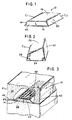
- a shaped article 10 of the invention can be in the form of a trapezium ( Figure 2), having no parallel upper, lower and side surfaces; or the article 12 ( Figure 1), preferably, is in the shape of a trapezoid having planar, horizontal upper (top) and lower (bottom) surfaces.
- the trapezoidally-shaped water seal article 12 includes a base or bottom planar surface 14 for adherence to a planar surface, e.g., of another cured concrete section, preferably having a width of about 1.905cm to about 5.08cm (about 3 ⁇ 4 to about 2 inches) most preferably about 3.175cm (about 1.25 inches); a parallel, horizontal upper surface 16 having a width of about 1.27cm to about 2.54cm (about 0.5 to about 1.0 inch), e.g.
- a scrim or netting material 22 preferably is secured to and is coextensive with the upper surface 16 for better securement of concrete nails driven vertically through the article 12 from the upper surface 16.
- the water seal article 12 can be adhesively secured using an adhesive, without the netting material 22, to prevent displacement of the water seal article while pouring an additional concrete section thereover.
- the shaped water seal article has a cross section in the shape of a trapezium including a planar, horizontal base or lower surface 24, an upper surface 26, and two non-parallel side surfaces 28 and 30 to provide a single. uncured concrete-contacting corner c 3 having an included angle ⁇ , as defined with reference to Fig. 1, preferably about 130°.
- the clay water seal preferably includes about 35% to 90% by weight water-swellable bentonite clay, such as sodium bentonite, about 10% to 65% by weight polypropene, polybutene, or mixture thereof, and optionally about 1% to about 20%, e.g., about 5% by weight of an elastomer, such as partially cross linked butyl rubber.
- water-swellable bentonite clay such as sodium bentonite
- polypropene polypropene
- polybutene polybutene
- elastomer such as partially cross linked butyl rubber
- polybutene as used throughout the specification including the claims, includes polyisobutylene.
- compositions useful in forming the clay water seal articles of the present invention include, for example, the compositions disclosed in U.S. Patent Nos. 4,534,925; 4,534,926; and 4,787,780, all of which are incorporated herein by reference.
- the clay seal is made of a non-toxic material, requiring no special handling equipment and does not contain any material that discolors or irritates the skin.
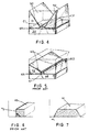
- the water seal article e.g., 12 is disposed such that the planar, lover surface 14 overlies an at least partially cured lower concrete Section 32, and an uncured concrete section 34 then is poured onto the lover concrete section 32, over the article 12.
- the at least partially cured concrete section 32 may be disposed underneath and in contact with the uncured, second concrete section 34, or the sections 32 and 34 may be laterally disposed with the water sealing article 12 disposed along an interface of the two sections 32 and 34.
- the water-swellable clay-containing water seal article of the present invention preferably is in the form of a flexible strip and is easily and efficiently installed by a single laborer.
- the seal may be supplied in the form of a coiled elongate strip that is unwound when applying the article between adjacent concrete sections. No split forming or splicing is required as may be required with other waterstop articles.
- the clay-containing water seal article of the present invention is adhered to the butt end of an at least partially cured section of concrete 32 and, preferably, is positioned a minimum of 5.08cm (2 inches) from the exterior joint surface (i.e., there should be a minimum of 5.08cm (2 inches) of concrete separating the water-swellable clay-containing sealing article 10 or 12 from the exterior sides 40 and 41 of the joint--see Fig. 3).
- the article 10 or 12 preferably is nailed or adhesively secured to the cured concrete section 32, e.g., using concrete nails 42, before pouring the second concrete section 34. Nailing down the clay seal in this manner will aid in preventing displacement of the clay seal during pouring of the concrete 34.
- an end surface 44 of the article 12 should abut an end of a previously placed strip, and the strips should not overlap.
- the second section of concrete 34 is poured to surround article 12, except for its bottom surface 14 in contact with lower concrete section 32, and onto an upper surface, or adjacent a side surface, of concrete section 32 to complete the joint.
- the developing expansion forces along planes 50 and 52 resulting when using the water-sealing articles of the present invention, are absorbed along substantially larger planes in the newly poured concrete, and at a substantially more upward angle from the corners C 1 and C 2 than the forces absorbed along planes 60 and 62, resulting from expansion of a rectangular or square-cornered prior art water-sealing article 63.
- expansion of the water seal articles of the present invention will be more easily absorbed by the curing concrete.
- the clay water sealing articles or the present invention will waterproof the concrete joint, preventing water from traversing any spaces 65 ( Figures 3 and 4) between the concrete sections 32 and 34.
- the clay water seal article expands, preferably to many times its non-hydrated volume, to form a water-impenetrable clay seal that completely prevents water from passing through the article.
- the angled lower elongate edges are less than 90°, preferably about 45° to about 80°. Hydration of this lover edge at the acute angle ⁇ 1 and/or ⁇ 2 , upon contact with water, permits the water seal article to hydrate at hydration volume H 1 , as shown in Figure 7, hydrating only a lower corner of the product.
- An article having a 90° lower angle ⁇ 3 permits hydration vertically upwardly, over hydration volume H 2 , resulting in greater forces acting on the newly formed concrete, along force planes 60 and 62 ( Figure 5) over a smaller newly poured concrete volume V 2 ( Figure 5), versus volume V 1 for the articles of the present invention.
- the clay water seal article of the present invention may be used in all environmental temperatures encountered at the installation location without becoming too stiff or brittle in cold temperatures, and without becoming too soft at higher temperatures. There is no need to heat the water seal article in cold temperatures to give it sufficient flexibility, and the water seal article remains totally flexible over time without shrinking, substantially hardening or oxidizing.
Landscapes
- Engineering & Computer Science (AREA)
- Structural Engineering (AREA)
- General Engineering & Computer Science (AREA)
- Civil Engineering (AREA)
- Architecture (AREA)
- Ocean & Marine Engineering (AREA)
- Mechanical Engineering (AREA)
- Physics & Mathematics (AREA)
- Environmental & Geological Engineering (AREA)
- Electromagnetism (AREA)
- Building Environments (AREA)
- Lining And Supports For Tunnels (AREA)
- On-Site Construction Work That Accompanies The Preparation And Application Of Concrete (AREA)
- Fire-Extinguishing Compositions (AREA)
- Polysaccharides And Polysaccharide Derivatives (AREA)
- Curing Cements, Concrete, And Artificial Stone (AREA)
- Transition And Organic Metals Composition Catalysts For Addition Polymerization (AREA)
- Addition Polymer Or Copolymer, Post-Treatments, Or Chemical Modifications (AREA)
- Paints Or Removers (AREA)
Claims (13)
- Mehrzahl von wasserdichten Betonabschnitten, umfassend:einen ersten Abschnitt (32) aus wenigstens teilweise ausgehärtetem Beton;einen zweiten Abschnitt (34) aus im wesentlichen nichtausgehärtetem Beton; undeinen geformten, gegen Wasser abdichtenden Artikel (12), der zwischen dem genannten ersten Abschnitt (32) und dem genannten zweiten Abschnitt (34) zum Verhindern von Wassereindringung zwischen den genannten beiden Betonabschnitten angeordnet ist, wobei der genannte geformte, gegen Wasser abdichtende Artikel (12) wenigstens ungefähr 20 Gewichtsprozent eines wasserquellfähigen Bentonittons enthält und eine viereckige Querschnittsform mit einer oberen Oberfläche (16; 26), zwei Seitenflächen (18, 20; 28,30) und einer Bodenfläche (14; 24) aufweist, wodurch bei Hydration des Artikels, wenn der genannte Artikel zwischen den genannten Betonabschnitten in Position ist, Ausdehnungskräfte durch den genannten zweiten Betonabschnitt (34) absorbiert werden, wobei sich die genannten Kräfte nach oben und nach außen von einem Rand (C1, C2; C3) des genannten gegen Wasser abdichtenden Artikels erstrecken, der durch den genannten zweiten Betonabschnitt umschlossen ist, der genannte Rand (C1, C2; C3) einen einbeschriebenen Winkel von wenigstens 100° hat, und der genannte Rand durch einen Schnittpunkt einer der genannten Seitenflächen (18, 20; 28, 30) des genannten Artikels und die genannte obere Oberfläche (16; 26) des genannten Artikels (12) begrenzt wird.
- Mehrzahl von wasserdichten Abschnitten nach Anspruch 1, wobei der genannte wasserquellfähige Ton des genannten gegen Wasser abdichtenden Artikels etwa 35% bis etwa 90% Bentonitton und ungefähr 10% bis etwa 65% Polypropen, Polybuten oder eine Mischung daraus aufweist.
- Mehrzahl von wasserdichten Abschnitten nach Anspruch 1 oder 2, wobei die genannte Ebene von Ausdehnungskräften und eine Linie senkrecht zu einer ebenen Bodenfläche (14; 24) des genannten Artikels (12), welche Linie durch den genannten Rand (C1, C2; C3) verläuft, einen kleineren Winkel als 45° bilden.
- Mehrzahl von wasserdichten Abschnitten nach einem der vorhergehenden Ansprüche, wobei der genannte wenigstens teilweise ausgehärtete Betonabschnitt (32) unter und in Berührung mit dem genannten Abschnitt (34) aus im wesentlichen nichtausgehärtetem Beton angeordnet ist.
- Mehrzahl von wasserdichten Abschnitten nach einem der vorhergehenden Ansprüche, die weiter einen Gitterstoff (22) befestigt an der oberen Oberfläche (16) des genannten gegen Wasser abdichtenden Artikels (12) umfasst und sich völlig gleich mit der genannten oberen Oberfläche erstreckt.
- Mehrzahl von wasserdichten Abschnitten nach einem der vorhergehenden Ansprüche, wobei der genannte einbeschriebene Winkel des genannten gegen Wasser abdichtenden Artikels (12) im Bereich von etwa 100° bis etwa 150° liegt.
- Mehrzahl von wasserdichten Abschnitten nach einem der vorhergehenden Ansprüche, wobei der genannte einbeschriebene Winkel des genannten gegen Wasser abdichtenden Artikels (12) in dem Bereich von etwa 120° bis etwa 140° liegt.
- Mehrzahl von wasserdichten Abschnitten nach einem der Ansprüche 1 bis 6, wobei der genannte einbeschriebene Winkel des genannten gegen Wasser abdichtenden Artikels (12) im Bereich von etwa 110° bis etwa 140° liegt.
- Mehrzahl von wasserdichten Abschnitten nach einem der vorhergehenden Ansprüche, wobei der genannte einbeschriebene Winkel des genannten gegen Wasser abdichtenden Artikels (12) etwa 130° beträgt.
- Mehrzahl von wasserdichten Betonabschnitten nach einem der vorhergehenden Ansprüche, wobei der genannte gegen Wasser abdichtende Artikel (12) eine trapezartige Form mit einem breiteren Grundteil (14) in Berührung mit dem genannten ersten Betonabschnitt (32) aufweist, und eine schmalere, parallele obere Oberfläche (16) aufweist, die durch den genannten zweiten Betonabschnitt (34) umgeben ist, wobei wenigstens ein oberer Rand (C1, C2) des genannten Trapezes einen einbeschriebenen Winkel im Bereich von wenigstens 100° aufweist.
- Mehrzahl wasserdichter Betonabschnitte nach Anspruch 10, wobei der genannte einbeschriebene Winkel im Bereich von etwa 100° bis etwa 150° liegt.
- Verfahren zur Imprägnierung eines Bereichs von potentiellem Wassereintritt zwischen einer Mehrzahl benachbarter Abschnitte (32, 34) aus Beton, umfassend:einen ersten Abschnitt (32) aus wenigstens teilweise ausgehärtetem Beton zu bilden;den geformten, gegen Wasser abdichtenden Artikel (12), wie er in einem der vorhergehenden Ansprüche definiert ist, angrenzend an und in Berührung mit dem genannten ersten Betonabschnitt (34) anzuordnen; undeinen zweiten Abschnitt (34) aus im wesentlichen nichtausgehärtetem Beton in Berührung mit dem genannten ersten Betonabschnitt auszubilden und den oberen Rand (C1, C2; C3) des genannten gegen Wasser abdichtenden Artikels (12) zu umschließen.
- Verfahren nach Anspruch 13 [sic], bei dem:der genannte gegen Wasser abdichtende Artikel (12) Ausdehnungskräfte erzeugt, die sich in den genannten zweiten Betonabschnitt (34) nach oben und nach außen von dem genannten Rand (C1, C2; C3) erstrecken; unddie genannten Ausdehnungskräfte durch mehr des genannten zweiten Betonabschnitts (34) absorbiert werden, als wenn der gegen Wasser abdichtende Artikel (12) einen einbeschriebenen Winkel von 90° an dem genannten Rand aufweist, wodurch die Auswirkung der Ausdehnungskräfte gegen den zweiten Betonabschnitt verringert wird.
Applications Claiming Priority (2)
| Application Number | Priority Date | Filing Date | Title |
|---|---|---|---|
| US08/008,736 US5339590A (en) | 1993-01-25 | 1993-01-25 | Trapezium-shaped aqueously-swelling concrete joint-sealing method |
| US8736 | 1993-01-25 |
Publications (3)
| Publication Number | Publication Date |
|---|---|
| EP0609040A2 EP0609040A2 (de) | 1994-08-03 |
| EP0609040A3 EP0609040A3 (en) | 1995-11-08 |
| EP0609040B1 true EP0609040B1 (de) | 2001-08-08 |
Family
ID=21733364
Family Applications (1)
| Application Number | Title | Priority Date | Filing Date |
|---|---|---|---|
| EP94300505A Expired - Lifetime EP0609040B1 (de) | 1993-01-25 | 1994-01-24 | Dichtungsartikel für Fugen in Betonkonstruktionen |
Country Status (9)
| Country | Link |
|---|---|
| US (2) | US5339590A (de) |
| EP (1) | EP0609040B1 (de) |
| JP (1) | JPH06235224A (de) |
| AT (1) | ATE204042T1 (de) |
| AU (1) | AU672261B2 (de) |
| CA (1) | CA2113041C (de) |
| DE (1) | DE69427881T2 (de) |
| FI (1) | FI940361A7 (de) |
| NO (1) | NO940239L (de) |
Cited By (1)
| Publication number | Priority date | Publication date | Assignee | Title |
|---|---|---|---|---|
| WO2003046300A1 (en) * | 2001-11-29 | 2003-06-05 | Commercial Waterproofing Services Pty Ltd | A method and means for waterproofing joints |
Families Citing this family (10)
| Publication number | Priority date | Publication date | Assignee | Title |
|---|---|---|---|---|
| US6026622A (en) * | 1995-06-23 | 2000-02-22 | Rascor Spezialbau Gmbh | Predetermined crack-joint |
| US6039503A (en) * | 1998-01-29 | 2000-03-21 | Silicone Specialties, Inc. | Expansion joint system |
| US20060009100A1 (en) * | 2004-07-08 | 2006-01-12 | Mcgroarty Bryan | Waterproofing membrane |
| CN100398751C (zh) * | 2007-06-28 | 2008-07-02 | 北京市水利科学研究所 | 天然河流膨润土夹层减渗方法 |
| US7739844B2 (en) * | 2008-05-27 | 2010-06-22 | American Fortress Homes, Inc. | Composite building panel |
| US20110198845A1 (en) * | 2010-02-18 | 2011-08-18 | Universal Polymer & Rubber Ltd. | Box culvert gasket seal |
| CN102587937B (zh) * | 2012-03-08 | 2014-03-12 | 长沙理工大学 | 复合式水工高压隧洞堵头 |
| KR102191221B1 (ko) | 2014-09-23 | 2020-12-16 | 삼성전자주식회사 | 저항 소자 및 이를 포함하는 반도체 소자 |
| DK4200488T3 (da) * | 2020-08-24 | 2025-12-22 | Hilti Ag | Tætningsprofil til kantfuger, gipsvæg og fastgørelsesfremgangsmåde |
| CN114370027A (zh) * | 2022-01-25 | 2022-04-19 | 上海千年城市规划工程设计股份有限公司 | 新建防洪墙与已建防洪墙的连接结构及施工方法 |
Family Cites Families (29)
| Publication number | Priority date | Publication date | Assignee | Title |
|---|---|---|---|---|
| US908780A (en) * | 1908-09-17 | 1909-01-05 | Lang & Gros Mfg Co | Gummed cloth. |
| US1559749A (en) * | 1922-04-28 | 1925-11-03 | Eric E Hall | Fastening strip |
| US3979846A (en) * | 1975-03-27 | 1976-09-14 | Alpha Nova Development Corporation | Poster supporting device |
| US4279547A (en) * | 1978-09-18 | 1981-07-21 | American Colloid Company | Bentonite-gelled oil waterproofing composition |
| CA1145131A (en) * | 1980-04-05 | 1983-04-26 | Hajime Yamaji | Aqueously-swelling water stopper and a process of stopping water thereby |
| AU527122B2 (en) * | 1980-10-17 | 1983-02-17 | Hayakawa Rubber Co. Ltd. | Reclaimed butyl rubber water stopper |
| CA1143957A (en) * | 1981-01-13 | 1983-04-05 | Bemalux Inc. | Waterproofing barrier |
| US4501788A (en) * | 1981-02-27 | 1985-02-26 | Clem Environmental Corp. | Waterproofing soil |
| US4467015A (en) * | 1981-11-02 | 1984-08-21 | Clem Arthur G | Waterproofing structure |
| DE3361123D1 (en) * | 1982-07-23 | 1985-12-05 | Alh Syst Ltd | Expansion joint |
| US4787780A (en) * | 1982-11-22 | 1988-11-29 | American Colloid Company | Method of waterproofing with a self-healing bentonite sheet material composite article |
| US4534925A (en) * | 1982-11-22 | 1985-08-13 | American Colloid Company | Uninhibited bentonite composition |
| US4534926A (en) * | 1982-11-22 | 1985-08-13 | American Colloid Company | Uninhibited bentonite composition |
| CA1217668A (en) * | 1983-01-31 | 1987-02-10 | Frank A. Braun | Expansion joint |
| JPS6079644A (ja) * | 1983-10-07 | 1985-05-07 | Mitsubishi Electric Corp | 大電力クライストロン用電子銃 |
| US4656062A (en) * | 1984-04-27 | 1987-04-07 | American Colloid Company | Self-healing bentonite sheet material composite article |
| MX163336A (es) * | 1984-11-29 | 1992-04-13 | American Colloid Co | Articulo de manufactura |
| US4810573A (en) * | 1984-11-29 | 1989-03-07 | American Colloid Company | Self-healing bentonite sheet material composite article |
| US4733513A (en) * | 1986-10-21 | 1988-03-29 | Schrader Ernest K | Tying bar for concrete joints |
| US4979846A (en) * | 1988-11-16 | 1990-12-25 | Ronald A. Hill | Contraction joint for concrete linings |
| US4997695A (en) * | 1988-11-21 | 1991-03-05 | James Clem Corporation | Clay mixture having contamination resistance |
| ATE105898T1 (de) * | 1990-02-15 | 1994-06-15 | American Colloid Co | Feuchtdichte platte fähig zur schnellen/verzögerten hydratation. |
| US5092091A (en) * | 1990-05-07 | 1992-03-03 | Hull Harold L | Concrete control key-joint and divider form |
| EP0461901A3 (en) * | 1990-06-15 | 1993-01-13 | American Colloid Company | Bentonite composition structurally supported with flexible material and method |
| JPH04153429A (ja) * | 1990-10-18 | 1992-05-26 | Hayakawa Rubber Co Ltd | 水膨張止水材 |
| JP2823969B2 (ja) * | 1991-03-11 | 1998-11-11 | 早川ゴム株式会社 | コンクリート打継部の止水工法 |
| AT395886B (de) * | 1991-03-19 | 1993-03-25 | Enertec Isoliermittelgesellsch | Einrichtung zur abdichtung der zwischen zwei baukoerpern, insbesondere zwischen zwei betonkoerpern, bestehenden arbeitsfuge |
| JP3172804B2 (ja) * | 1992-02-19 | 2001-06-04 | 株式会社信明産業 | コンクリート打ち継ぎ用の水膨張性止水材 |
| US5197250A (en) * | 1992-05-12 | 1993-03-30 | Tremco Incorporated | Wide expansion joint system |
-
1993
- 1993-01-25 US US08/008,736 patent/US5339590A/en not_active Expired - Lifetime
-
1994
- 1994-01-07 CA CA002113041A patent/CA2113041C/en not_active Expired - Fee Related
- 1994-01-24 JP JP6005588A patent/JPH06235224A/ja active Pending
- 1994-01-24 NO NO940239A patent/NO940239L/no unknown
- 1994-01-24 AT AT94300505T patent/ATE204042T1/de not_active IP Right Cessation
- 1994-01-24 DE DE69427881T patent/DE69427881T2/de not_active Expired - Lifetime
- 1994-01-24 EP EP94300505A patent/EP0609040B1/de not_active Expired - Lifetime
- 1994-01-25 FI FI940361A patent/FI940361A7/fi unknown
- 1994-01-25 AU AU54718/94A patent/AU672261B2/en not_active Ceased
- 1994-05-10 US US08/241,032 patent/US5473848A/en not_active Expired - Lifetime
Cited By (1)
| Publication number | Priority date | Publication date | Assignee | Title |
|---|---|---|---|---|
| WO2003046300A1 (en) * | 2001-11-29 | 2003-06-05 | Commercial Waterproofing Services Pty Ltd | A method and means for waterproofing joints |
Also Published As
| Publication number | Publication date |
|---|---|
| AU672261B2 (en) | 1996-09-26 |
| DE69427881T2 (de) | 2001-11-22 |
| EP0609040A3 (en) | 1995-11-08 |
| ATE204042T1 (de) | 2001-08-15 |
| US5473848A (en) | 1995-12-12 |
| NO940239L (no) | 1994-07-26 |
| CA2113041A1 (en) | 1994-07-26 |
| FI940361A7 (fi) | 1994-07-26 |
| JPH06235224A (ja) | 1994-08-23 |
| NO940239D0 (no) | 1994-01-24 |
| DE69427881D1 (de) | 2001-09-13 |
| AU5471894A (en) | 1994-07-28 |
| FI940361A0 (fi) | 1994-01-25 |
| US5339590A (en) | 1994-08-23 |
| CA2113041C (en) | 1998-08-18 |
| EP0609040A2 (de) | 1994-08-03 |
Similar Documents
| Publication | Publication Date | Title |
|---|---|---|
| US5794388A (en) | Apparatus for controlling water seepage at a structural interface | |
| US4927291A (en) | Joint seal for concrete highways | |
| US4824283A (en) | Sealed highway joint and method | |
| US5845456A (en) | Basement waterproofing | |
| EP0609040B1 (de) | Dichtungsartikel für Fugen in Betonkonstruktionen | |
| US20070266658A1 (en) | Building Structure and a Method of Forming a Building Structure | |
| EP3014024A1 (de) | Wanddichtungssystem | |
| KR102614901B1 (ko) | 합벽, cip벽, 지하벽, h파일벽, 흙막이벽, 지하주차장, 지하구조물의 방수, 방근, 조경, 건설, 공사, 방근방수 공법 | |
| JPH052049B2 (de) | ||
| US4459063A (en) | Building construction | |
| EP0686221B1 (de) | Verbesserungen bezüglich der termitenbekämpfung | |
| CA2477055A1 (en) | Method and apparatus for deflecting liquid from a foundation wall | |
| US5452558A (en) | Method for permanently repairing and sealing roofs | |
| JPH0665935A (ja) | 地下構造物の防水工法および防水層の保護プレート | |
| JP2002059108A (ja) | アスファルトマットの水中遮水工法 | |
| JPH0735506U (ja) | 透水性舗装用目地型枠 | |
| JP2891670B2 (ja) | コンクリート製品の可撓継手構造及びその可撓継手構造を有するコンクリート製品 | |
| JPS621930A (ja) | 地下建造物の基礎部の構造 | |
| JP7183218B2 (ja) | 鋼製遮水壁、鋼製遮水壁の遮水方法 | |
| AU734570B2 (en) | Termite barrier receptor | |
| JPS6328253Y2 (de) | ||
| AU695436B2 (en) | Improvements relating to termite control | |
| KR200201192Y1 (ko) | 수팽창성 수밀형 고무 지수재 | |
| JPH06146238A (ja) | 構造物と遮水シ−トとの止水固定構造 | |
| JPH0337625B2 (de) |
Legal Events
| Date | Code | Title | Description |
|---|---|---|---|
| PUAI | Public reference made under article 153(3) epc to a published international application that has entered the european phase |
Free format text: ORIGINAL CODE: 0009012 |
|
| AK | Designated contracting states |
Kind code of ref document: A2 Designated state(s): AT BE CH DE DK FR GB IT LI LU NL SE |
|
| PUAL | Search report despatched |
Free format text: ORIGINAL CODE: 0009013 |
|
| AK | Designated contracting states |
Kind code of ref document: A3 Designated state(s): AT BE CH DE DK FR GB IT LI LU NL SE |
|
| RAP1 | Party data changed (applicant data changed or rights of an application transferred) |
Owner name: AMCOL INTERNATIONAL CORPORATION |
|
| 17P | Request for examination filed |
Effective date: 19960126 |
|
| 17Q | First examination report despatched |
Effective date: 19990219 |
|
| GRAG | Despatch of communication of intention to grant |
Free format text: ORIGINAL CODE: EPIDOS AGRA |
|
| GRAG | Despatch of communication of intention to grant |
Free format text: ORIGINAL CODE: EPIDOS AGRA |
|
| GRAG | Despatch of communication of intention to grant |
Free format text: ORIGINAL CODE: EPIDOS AGRA |
|
| GRAH | Despatch of communication of intention to grant a patent |
Free format text: ORIGINAL CODE: EPIDOS IGRA |
|
| GRAH | Despatch of communication of intention to grant a patent |
Free format text: ORIGINAL CODE: EPIDOS IGRA |
|
| GRAA | (expected) grant |
Free format text: ORIGINAL CODE: 0009210 |
|
| ITF | It: translation for a ep patent filed | ||
| AK | Designated contracting states |
Kind code of ref document: B1 Designated state(s): AT BE CH DE DK FR GB IT LI LU NL SE |
|
| PG25 | Lapsed in a contracting state [announced via postgrant information from national office to epo] |
Ref country code: NL Free format text: LAPSE BECAUSE OF FAILURE TO SUBMIT A TRANSLATION OF THE DESCRIPTION OR TO PAY THE FEE WITHIN THE PRESCRIBED TIME-LIMIT Effective date: 20010808 Ref country code: LI Free format text: LAPSE BECAUSE OF FAILURE TO SUBMIT A TRANSLATION OF THE DESCRIPTION OR TO PAY THE FEE WITHIN THE PRESCRIBED TIME-LIMIT Effective date: 20010808 Ref country code: FR Free format text: LAPSE BECAUSE OF FAILURE TO SUBMIT A TRANSLATION OF THE DESCRIPTION OR TO PAY THE FEE WITHIN THE PRESCRIBED TIME-LIMIT Effective date: 20010808 Ref country code: CH Free format text: LAPSE BECAUSE OF FAILURE TO SUBMIT A TRANSLATION OF THE DESCRIPTION OR TO PAY THE FEE WITHIN THE PRESCRIBED TIME-LIMIT Effective date: 20010808 Ref country code: BE Free format text: LAPSE BECAUSE OF FAILURE TO SUBMIT A TRANSLATION OF THE DESCRIPTION OR TO PAY THE FEE WITHIN THE PRESCRIBED TIME-LIMIT Effective date: 20010808 Ref country code: AT Free format text: LAPSE BECAUSE OF FAILURE TO SUBMIT A TRANSLATION OF THE DESCRIPTION OR TO PAY THE FEE WITHIN THE PRESCRIBED TIME-LIMIT Effective date: 20010808 |
|
| REF | Corresponds to: |
Ref document number: 204042 Country of ref document: AT Date of ref document: 20010815 Kind code of ref document: T |
|
| REG | Reference to a national code |
Ref country code: CH Ref legal event code: EP |
|
| REF | Corresponds to: |
Ref document number: 69427881 Country of ref document: DE Date of ref document: 20010913 |
|
| PG25 | Lapsed in a contracting state [announced via postgrant information from national office to epo] |
Ref country code: SE Free format text: LAPSE BECAUSE OF FAILURE TO SUBMIT A TRANSLATION OF THE DESCRIPTION OR TO PAY THE FEE WITHIN THE PRESCRIBED TIME-LIMIT Effective date: 20011108 Ref country code: DK Free format text: LAPSE BECAUSE OF FAILURE TO SUBMIT A TRANSLATION OF THE DESCRIPTION OR TO PAY THE FEE WITHIN THE PRESCRIBED TIME-LIMIT Effective date: 20011108 |
|
| REG | Reference to a national code |
Ref country code: GB Ref legal event code: IF02 |
|
| NLV1 | Nl: lapsed or annulled due to failure to fulfill the requirements of art. 29p and 29m of the patents act | ||
| EN | Fr: translation not filed | ||
| PG25 | Lapsed in a contracting state [announced via postgrant information from national office to epo] |
Ref country code: LU Free format text: LAPSE BECAUSE OF NON-PAYMENT OF DUE FEES Effective date: 20020124 |
|
| REG | Reference to a national code |
Ref country code: CH Ref legal event code: PL |
|
| PLBE | No opposition filed within time limit |
Free format text: ORIGINAL CODE: 0009261 |
|
| STAA | Information on the status of an ep patent application or granted ep patent |
Free format text: STATUS: NO OPPOSITION FILED WITHIN TIME LIMIT |
|
| 26N | No opposition filed | ||
| PGFP | Annual fee paid to national office [announced via postgrant information from national office to epo] |
Ref country code: DE Payment date: 20110119 Year of fee payment: 18 Ref country code: IT Payment date: 20110122 Year of fee payment: 18 |
|
| PGFP | Annual fee paid to national office [announced via postgrant information from national office to epo] |
Ref country code: GB Payment date: 20110119 Year of fee payment: 18 |
|
| GBPC | Gb: european patent ceased through non-payment of renewal fee |
Effective date: 20120124 |
|
| PG25 | Lapsed in a contracting state [announced via postgrant information from national office to epo] |
Ref country code: DE Free format text: LAPSE BECAUSE OF NON-PAYMENT OF DUE FEES Effective date: 20120801 Ref country code: GB Free format text: LAPSE BECAUSE OF NON-PAYMENT OF DUE FEES Effective date: 20120124 |
|
| REG | Reference to a national code |
Ref country code: DE Ref legal event code: R119 Ref document number: 69427881 Country of ref document: DE Effective date: 20120801 |
|
| PG25 | Lapsed in a contracting state [announced via postgrant information from national office to epo] |
Ref country code: IT Free format text: LAPSE BECAUSE OF NON-PAYMENT OF DUE FEES Effective date: 20120124 |