EP0609084A2 - Instrument courbé orientable actionné par moteur - Google Patents
Instrument courbé orientable actionné par moteur Download PDFInfo
- Publication number
- EP0609084A2 EP0609084A2 EP94300614A EP94300614A EP0609084A2 EP 0609084 A2 EP0609084 A2 EP 0609084A2 EP 94300614 A EP94300614 A EP 94300614A EP 94300614 A EP94300614 A EP 94300614A EP 0609084 A2 EP0609084 A2 EP 0609084A2
- Authority
- EP
- European Patent Office
- Prior art keywords
- instrument
- disposed
- opening
- bend region
- region
- Prior art date
- Legal status (The legal status is an assumption and is not a legal conclusion. Google has not performed a legal analysis and makes no representation as to the accuracy of the status listed.)
- Granted
Links
Images


Classifications
-
- A—HUMAN NECESSITIES
- A61—MEDICAL OR VETERINARY SCIENCE; HYGIENE
- A61B—DIAGNOSIS; SURGERY; IDENTIFICATION
- A61B17/00—Surgical instruments, devices or methods
- A61B17/32—Surgical cutting instruments
- A61B17/320016—Endoscopic cutting instruments, e.g. arthroscopes, resectoscopes
- A61B17/32002—Endoscopic cutting instruments, e.g. arthroscopes, resectoscopes with continuously rotating, oscillating or reciprocating cutting instruments
-
- A—HUMAN NECESSITIES
- A61—MEDICAL OR VETERINARY SCIENCE; HYGIENE
- A61B—DIAGNOSIS; SURGERY; IDENTIFICATION
- A61B17/00—Surgical instruments, devices or methods
- A61B17/28—Surgical forceps
- A61B17/29—Forceps for use in minimally invasive surgery
- A61B2017/2901—Details of shaft
- A61B2017/2905—Details of shaft flexible
-
- A—HUMAN NECESSITIES
- A61—MEDICAL OR VETERINARY SCIENCE; HYGIENE
- A61M—DEVICES FOR INTRODUCING MEDIA INTO, OR ONTO, THE BODY; DEVICES FOR TRANSDUCING BODY MEDIA OR FOR TAKING MEDIA FROM THE BODY; DEVICES FOR PRODUCING OR ENDING SLEEP OR STUPOR
- A61M25/00—Catheters; Hollow probes
- A61M25/01—Introducing, guiding, advancing, emplacing or holding catheters
- A61M25/0105—Steering means as part of the catheter or advancing means; Markers for positioning
- A61M25/0133—Tip steering devices
- A61M25/0138—Tip steering devices having flexible regions as a result of weakened outer material, e.g. slots, slits, cuts, joints or coils
Definitions
- This invention relates to surgical instruments, and in particular to powered arthroscopic surgical instruments.
- Powered arthroscopic surgical instruments typically include a rigid, stationary outer tube within which a a rigid inner tube is rotated by a motor.
- a cutting implement such as a blade or abrading burr, is disposed on the distal end of the inner tube. Tissue or bone is exposed to the cutting implement through an opening in the distal end of the outer tube, and tissue or bone fragments cut by the rotating blade or burr are drawn through the interior of the inner tube along with irrigating fluid by the use of suction applied at the proximal end of the instrument.
- Examples of such surgical instruments are described in US Patent Nos. 4203444, 4274414, 4834729 and 4842578, all of which are assigned to the present applicant.
- Some arthroscopic surgical instruments are linear, that is, straight between their proximal and distal ends. Others are curved to facilitate positioning the cutting implement against tissue to be cut without requiring that the instrument be removed from the body and reinserted through an additional puncture.
- a region of the inner tube is flexible to enable the inner tube to accept the curvature imposed by the outer tube while transmitting the torsion applied by the motor to the blade. In both cases, the user changes the orientation of the cutting implement by rotating the instrument.
- a general aspect of the invention is a surgical instrument that includes a first member that has an opening in its distal region for admitting tissue and that is rotatable with respect to a base from which the first member extends to allow the rotational orientation of the opening to be selectively changed with respect to the axis of the instrument; a second member is disposed within the first member to transmit force to move a cutting implement disposed at its distal end and cause it to cut tissue that is exposed to the implement through the opening.
- a surgical instrument disposed generally along an axis, said surgical instrument comprising a first member that extends distally from a base and has an opening in a distal region thereof for admitting tissue, a second member disposed within said first member for transmitting force applied to a proximal end thereof to move a cutting implement disposed at a distal end thereof and cause it to cut tissue that is exposed to said implement through said opening, and means for rotating said first member with respect to said base to selectively change a rotational orientation of said opening with respect to said axis.
- the invention allows the user to change the angle of attack of the cutting implement (ie. rotational orientation at which the cutting implement is exposed to tissue) by rotating the first member only, without turning the entire instrument.
- the user can maintain the instrument in an essentially fixed position, while rotationally varying the locations at which cutting performed. This minimizes the manipulation require of the entire instrument, thereby facilitating the surgical procedure and reducing patient discomfort and the risk of surgical side effects.
- Preferred embodiments include the following features.
- the first member is provided with a bend region that angularly offsets the distal region (and hence the opening) from the axis of the instrument in a selected direction.
- the instrument is curved.
- the curved nature of the instrument allows the user (eg. a surgeon) to position the cutting implement adjacent to tissue and other body material that is relatively difficult to reach with a straight instrument without having to remove and re-introduce the instrument through additional incisions in the body. Because the first member (rather than the entire instrument) is rotated to vary the angle of cutting attack, the cutting implement is maintained in close contact with the tissue being cut at all times.
- the first member is relatively flexible, at least in the bend region, to allow the rotational orientation of the opening to be changed without changing the direction of the offset, and at least a portion of the second member that is disposed in the bend region is also relatively flexible to transmit the applied force through the bend region to the cutting implement.
- the first member is relieved in the bend region to provide the relative flexibility.
- the first member is a tube having rigid proximal and distal regions that are connected by the relieved portion.
- the first member is relieved with a plurality of discrete openings disposed in its walls.
- the openings are a series of axially spaced, circumferentially extending slots that extend radially into the first member. Adjacent slots extend into the first member from opposite directions.
- the configuration and orientation of the slots help ensure uniform flexibility while providing the flexible region of the first member with sufficing torsional stiffness to transmit rotation applied by the user at, eg. the base through the bend region to rotate the opening.
- a pliable sheath (such as a shrink-wrap tube) may be disposed over the first member in the bend region to cover the openings.
- the second member also is a tube having rigid proximal and distal ends, and the portion of the second member that lies within the bend region is relieved with a series of axially spaced, circumferentially extending slots to provide the relative flexibility.
- a motor applies the force as torque to the proximal end of the second member, and the slotted flexible portion is configured to transmit the torque through the bend region to rotate the cutting implement (which is, eg. a blade).
- pliable material is disposed in some or all of the slots. The pliable material helps avoid tissue fragments severed by the cutting implement (which, together with irrigation fluid, are removed by suction from the surgical site through the second member) from becoming lodged on the edges of the slots. The pliable material also reduces the axial compressibility of the inner tube and leaks in the suction applied to the proximal end of the inner tube.
- a surgical instrument disposed generally along an axis, said surgical device comprising a first member that extends distally from a base and has an opening in a distal region thereof for admitting tissue, means for providing said first member with a bend region that angularly offsets said distal region from said axis in a selected direction, a second member disposed within said first member, for transmitting force applied to a proximal end thereof to move a cutting implement disposed at a distal end thereof and cause it to cut tissue that is exposed to said implement through said opening, at least a portion of said second member that is disposed within said bend region being relatively flexible, means for rotating said first member with respect to said base, said first member being relatively flexible at least in said bend region to transmit said rotation through said bend region to selectively change a rotational orientation of said opening with respect to said axis without changing said selected direction of said offset.
- the bend region is provided by a rigid member that is disposed coaxially with the first and second members and is curved in the bend region.
- the rigid member radially separates the first member from the second member at least in the bend region. This helps avoid interference between the flexible regions (eg. the edges of the slots) as the second member moves.
- the second member is disposed within the rigid member, which is in turn disposed within the first member.
- the rigid member has an open distal tip disposed proximally of the cutting implement and opening, and the first and second members are configured to contact each other distally of the tip to maintain the cutting implement in tissue cutting relationship with edges of the opening.
- a portion of the distal region of the first member has a reduced inner diameter with respect to the remainder of the first member to provide the contact with the second member and abuts the tip of the rigid member.
- the reduced inner diameter equals the inner diameter of the rigid member to provide a substantially smooth chamber within which the second member rotates, thus reducing the risk of the inner member seizing as it rotates.
- the first member is rotatable to allow orientation of the opening to be changed over an arc of at least 180°C, and preferably over a range of 360°C.
- the outer tube is rotated manually, using a knob that is rigidly secured to a proximal end of the first member and rotatably mounted to a stationary portion of the base.
- a ratchet mechanism mounts the knob to the base to allow the knob to be selectively rotated to a plurality of discrete positions, thereby to allow the opening for the cutting implement to be selectively positioned to a corresponding plurality of discrete rotational orientations.
- a surgical instrument disposed generally along an axis, said surgical device comprising, an outer tube that extends distally from a base and has an opening in a distal region thereof for admitting tissue, a stationary support tube that extends distally from a base and is disposed within said outer tube, said support tube including a bend region disposed between said base and said distal region to angularly offset said distal region from said axis in a selected direction, an inner tube disposed within said support tube for transmitting force applied to a proximal end thereof to move a cutting implement disposed at a distal end thereof cause it to cut tissue that is exposed to said implement through said opening, at least a portion of said inner tube that is disposed within said bend region being relatively flexible, and means for rotating said outer tube with respect to said base about said stationary support tube, said outer tube being relatively flexible at least in said bend region to transmit said rotation through said bend region to selectively change a rotational orientation of said opening with respect to said axis without changing said selected direction of said offset.
- the stationary portion includes a plurality of recesses each of which corresponds to one of the discrete positons, and the knob has a plunger that selectively engages the recesses to maintain the opening in the discrete rotational orientation that the user has selected.
- the knob is resiliently biased toward said stationary portion to retain said plunger in a recess. This helps avoid accidental rotation of the first member with respect to the base.
- the proximal end of the second member is secured to a drive shaft mounted for movement (eg. rotation) with respect to the stationary portion and the knob.
- the drive shaft is driven by a motor to rotate the second member with respect to the first member and move the cutting implement.
- the second member receives suction at its proximal end to draw tissue fragments and other body material cut by the cutting implement thorugh the second member away from a surgical site while the instrument remains in situ for futher cutting.
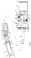
- Figure 1 shows a surgical instrument according to the invention, having a cutting implement that is adjustable to different rotational positions.
- Figure 2 is a partial cross-sectional view of portions of the instrument of Figure 1, showing details of the tip and base.
- Figures 3 - 5 show inner, intermediate, and outer tubes, respectively, of the surgical instrument of Figure 1.
- Figure 6 is a cross-section of the base of the surgical instrument, taken along line 6-6 of Figure 2.
- Figure 7 shows the surgical instrument of Figure 1 in use.
- surgical instrument 10 suitable for performing, eg. closed, arthroscopy surgery on the knee with a surgical tool 11, includes an outer tube 12 within which a rotating inner tube 14 is coaxially disposed.
- the distal end of outer tube 12 includes an opening 13, the edges of which are sharpened and serrated, through which a cutting implement 15 (formed by sharpened, serrated edges of a similar opening in the distal end of inner tube 14) of surgical tool 11 is periodically exposed as inner tube 14 rotates.
- a rigid, stationary intermediate tube 16 is disposed coaxially between outer tube 12 and inner tube 14.
- Intermediate tube 16 is curved through a bend region 18 disposed slightly proximally of the distal end 20 of tube 16 to angularly offset surgical tool 11 from a generally straight axis 24 of surgical instrument 10. Bend region 18 enables surgical instrument 10 to operate on surgical areas that are difficult to reach with a straight instrument.
- Tubes 12, 14 and 16 are proximally supported by a base 25.
- inner tube 14 includes a slotted, flexible region 26 disposed within bend region 18 to accept the curvature imposed by bend region 18 and transmit torque (and other forces) applied at base 25 through bend region 18 to rotate cutting implement 15 with sufficient force to sever tissue or other body material exposed through opening 13.
- Outer tube 12 has a slotted, flexible region 28 that envelopes bend region 18 and allows the user to rotate outer tube 12 with respect to base 25, despite the curvature imposed by bend region 18. This feature enables the user to selectively change the rotational orientation of opening 13, and hence surgical tool 11, with respect to axis 24 without rotating the entire surgical instrument 10, and thus without changing the orientation of bend region 18 and the angular offset that it provides. As a result, the user can maintain surgical instrument 10 in an essentially fixed position, while changing the angle of attack of cutting implement 15 by rotating outer tube 12.
- inner tube 14 is made from metal, such as stainless steel, and has rigid proximal and distal regions 30, 32, that are connected by flexible region 26.
- Flexible region 26 is relieved with an axially extending series of circumferential slots 34 disposed in the walls 36 of tube 14 and is continuous with the adjacently disposed proximal and distal regions 30, 32.
- Slots 34 are perpendicular to the longitudinal axis 38 of tube 14 and are arranged in a symmetrical pattern along the length L1 of flexible region 26 to provide uniform flexibility as inner tube 14 rotates. This minimizes torsional stresses on inner tube 14 and helps prolong the operating life of surgical instrument 10.
- Slots 34 are disposed parallel to each other (vertically in Figure 3) along length L1. Adjacent slots 34 extend into tube 14 from opposite directions (eg. from above and below tube 14 in Figure 3) and are circumferentially offset from each other by 180°.
- the number of slots 34, their dimensions (ie. their width and depth), and the spacing between adjacent slots are a function of the desired degree of flexibility. For example, the width of each slot 34 and the spacing between slots 34 and the spacing between slots 34 each are 0.020 inches.
- a tab 40 bounds each slot 34 circumferentially, and adjacent tabs 40 are interconnected by annular rings 42, which provide the spacing between adjacent slots 34.
- the interconnected series of rings 42 and tabs 40 provide a series of interconnected, integrally formed "U" shaped leaf springs along the length L1 of flexible region that give uniform flexibility and efficiently transmit torque (ie. rotational force) applied at proximal region 30 of tube 14 to distal region 32 through the curvature imposed by bend region 18 ( Figure 1).
- the depth of slots 34 ie. the amount by which slots 34 extend radially into tube 14
- slots 34 have a depth of about 75% of the outer diameter (0.135 inches) of inner tube 14.
- the length L1 of flexible region 26 is a function of the length of bend region 18.
- Flexible region 26 should be sufficiently long (eg. 0.70 inches) so as to span the entire length of bend region 18, with adjacent rigid regions 30, 32 lying within straight regions of stationary intermediate tube 16. This allows flexible region 26 to make a smooth transition between the straight regions of intermediate tube 16 and bend region 18, thereby reducing stresses imposed by the curved inner walls of bend region on walls 36 of inner tube 14.
- Flexible region 26 can be formed by any suitable method. Examples include wire EDM (electric discharge machining) and sawing. Both are described in the aforementioned US Patent Application Serial No.07/634599.
- Distal region 32 of inner tube 14 supports cutting implement 15 (which is, for example, stainless steel and attached to tube 14 by welding or brazing).
- Cutting implement 15 is defined by serrated, sharpened edges 44 of a distal opening 46 in tube 14 and is sized to provide a close running fit with the distal end of outer tube 12 for efficient cutting.
- Opening 46 is an extension of a central aperture 48 in inner tube that runs the entire length of tube 14.
- Proximal region 30 of inner tube 14 is rigidly mounted to a drive shaft 50 that rotates within base 25. Central aperture 48 terminates in a vacuum source opening 52 in drive shaft 50.
- the proximal end 53 of drive shaft 50 fits into a handpiece 110 ( Figure 7), which includes a motor 112 for rotating drive shaft 50 and inner tube 14 with resepct to tubes 12, 16.
- a handpiece 110 Figure 7
- Opening 52 is coupled to a vacuum source 114 ( Figure 7) during operation to remove severed tissue and irrigating fluid from the surgical site via aperture 48 in a manner described in detail below.
- Figure 4 shows intermediate tube 16 (before bend region 18 is formed), which is made from a rigid material such as metal (eg. stainless steel).
- Intermediate tube 16 is hollow along its entire length to provide a passage 54 that receives inner tube 14, which protrudes through the open distal end 20 of intermediate tube 16 ( Figure 2).
- the inner diameter of intermediate tube 16 is only slightly larger than the outer diameter of inner tube 14 (eg. by approximately 0.002 inches); this allows inner tube 14 to rotate freely but helps minimize wobbling of tube 14 to keep the sharp cutting edges of implement 15 and opening 13 closely aligned.
- intermediate tube 16 The proximal end of intermediate tube 16 is rigidly mounted to a hub 56 of base 25.
- a cavity 58 in hub 56 communicates with passage 54 and is configured to receive drive shaft 50.
- inner tube 14 is inserted through hub 56 into intermediate tube 16 (before bend region 18 is formed).
- a pliable fitting 60 retains drive shaft 50 within hub 56. Fitting 60 provides a fluid-tight seal when base 25 is inserted into handpiece 110.
- outer tube 12 is essentially a larger version of inner tube 14 and includes rigid proximal and distal regions 62, 64 that are integrally connected by flexible region 28.
- Flexible region 28 includes an axially extending series of slots 66 disposed perpendicularly to the longitudinal axis 68 of tube 12 and arranged in a symmetrical pattern along the length L2 of flexible region 28. Adjacent slots 66 extend radially into tube 12 in opposite directions (ie. from above and below tube 12 in Figure 5). Each slot 66 is approximately 0.025 inches wide and has a depth of about 0.140 inches.
- Each slot 66 is bounded by a tab 70.
- Adjacent tabs 70 are circumferentially offset by 180° and are connected by rings 72 (each of which has the same width as slots 66) to form a series of "U" shaped spings that are continuous with each other and with proximal and distal regions 62, 64.
- flexible region 28 is both sufficiently pliable to accept the curvature imposed by bend region 18 and sufficiently torsionally stiff to transmit applied rotational force through bend region 18 to rotate opening 13.
- Length L2 should be such that flexible region 28 spans the entire length of bend region 18, with the adjacently-disposed rigid portions 62, 64 of outer tube being aligned with straight portions of intermediate tube 16.
- a distal extension 74 having the same inner diameter as intermediate tube 16 is secured to outer tube 12 at distal end 64.
- Extension 74 is, eg. stainless steel and is welded or brazed to outer tube 12, which can be a softer material, such as aluminium.
- the proximal end of extension 74 has a reduced outer diameter to allow it to be disposed within outer tube 12 and about intermediate tube 16 at joint 76.
- a shoulder 78 on distal extension 74 limits the amount by which extension 74 is inserted into distal end 64 during assembly.
- Opening 13 is disposed in a distal tip 80 of extension 74 and faces somewhat to the side of outer tube 12. That is, opening 13 does not extend completely to the centreline 82 of extension 74. As a result, while surgical tool will cut tissue that enters opening 13 from the distal end of instrument 10, the majority of the cutting action is to one side. Moreover, tip 80 provides distal support for the rotating inner tube 14. The edges 84 of opening 13 are sharpened and serrated to cooperate with sharp edges 44 of cutting implement 15. The clearance between inner tube 14 and the inner diameter of outer tube extension 74 and intermediate tube 16 is small (eg. approximately 0.002 inches) to maintain the close running fit between edges 44, 84 while allowing inner tube 14 to rotate freely. The identical inner diameters of extension 74 and intermediate tube 16 avoid inner tube 14 scoring or seizing as it rotates.
- Proximal region 62 ( Figure 5) of outer tube 12 is rigidly secured to a drum 86 at a sealed joint.
- Drum 86 serves as a knob to enable the user to manually rotate tube 14, and is rotatably mounted to base 25 in a manner described below.
- a central passage 88 extends through outer tube 12 and drum 86 to receive intermediate tube 16 and inner tube 14.
- the inner diameter of outer tube 12 proximally of extension 74 only slightly exceeds the outer diameter of intermediate tube 16 (eg. by approximately 0.002 inches). This allows the user to rotate outer tube 12 but avoids excessive play between tubes 12, 16.
- outer tube 12 and drum 86 are rotatably mounted to base 25 with a spring-loaded rotation assembly 90.
- Drum 86 is captured between the distal end 57 of hub 56 and a faceplate 92, which includes an opening 94 ( Figure 1) through which outer tube 12 projects.
- a pair of axially extending bars 96 connect faceplate 92 to a sleeve 98 that is rigidly mounted to a hub distal end 57 by one or more press-fit pins 100.
- a spring 102 eg. a wave washer, which fits within a recess (not shown) in faceplate 92, resiliently biases drum 86 toward hub 56.
- distal end 57 of hub 56 includes a series of (such as eight) rounded recesses 104a-104h disposed in an annular surface 105 of hub 56 that faces drum 86.
- Recesses 104a-104h are spaced by equal amounts (such as by 45°) around the circumference of hub 56.
- Surface 105 is flat between adjacent recesses 104a-104h.
- a plunger 106 having a spring-loaded, ball shaped tip 107 is threaded into drum 86. Tip 107 is resiliently urged against hub 56 and into a selected one of recesses 104a-104h by spring 102.
- the user can selectively rotate drum 86 and hence outer tube 12 and surgical tool opening 13 to one of eight discrete rotational orientations.
- the biasing provided by spring 102 maintains plunger tip 107 in the selected recess 104a-104h to avoid accidental rotation.
- tip 107 is compressed into plunger 106 by flat surfaces 105.
- Recesses 104a-104h are arranged to allow opening 13 to be rotated in a ratchet-like fashion to commonly used positions with respect to axis 24.
- positioning plunger tip 107 in recess 104a orients opening 13 oppositely from the direction of curvature of bend region 18 (Figure 2), that is, is aligned with the curvature direction and is oriented downwardly (the position shown in Figure 2).
- recesses 104c and 104g correspond to left and right orientations.
- Recesses 104b, 104d, 104f and 104h provide intermediate positions for opening 13.
- surgical instrument 10 is inserted into the distal end of a handpiece 110 and is introduced as shown through a puncture wound 120 into the knee joint 122, below the patella.
- Light is projected into the joint via a second puncture 124 using a fibre optic light source 126, and a visual image of the surgical site is returned through a separate optical path to a television camera 128.
- the image is delivered by camera 128 onto a television screen 130 for viewing by the surgeon. (Alternatively, the surgeon can view the image using an eyepiece, or the image can be recorded).
- the surgeon operates surgical tool 11 by activating motor 112, which receives operating potential and current from power supply 116.
- Motor 112 engages and rotates drive shaft 50, thereby applying rotational force to inner tube 14 and rotating tube 14 with respect to tubes 12, 16.
- the surgeon controls rotational speed and direction (either unidirectional or oscillatory) using foot switches 116a, 116b, which control the magnitude and polarity of operating potential and current provided by power supply 116 to motor 112.
- Motor 112 is capable of rotating inner tube 14 over a wide range of speeds, eg. between about 100 rpm and 5000 rpm, and can deliver a torque of up to 25 oz inches.
- instrument 10 has rotational and torsional limits. To prevent the surgeon from inadvertently operating instrument 10 at dangerously high speeds and torques, instrument 10 identifies to sensors (not shown) in handpiece 110 what type of instrument it is, and the spped of and torsion applied by motor 112 is controlled so that these limits are not exceeded. (This control technique is described in the aforementioned US Patent No.4705038.
- region 26 is sufficiently flexible to accept the curvature imposed by bend region 18, it has a high degree of torsional stiffness and thus provides good torque response. That is, torsion applied by motor 112 is transmitted to distal region 32 of inner tube 14 substantially immediately when inner tube 14 is rotated from its rest position, without requiring any significant "preloading" of flexible region 26 prior to passing the torque to distal end 32. Also, flexible region 26 does not expand in diameter by any significant amount as it rotates and applies torque to distal end 32, reducing the possibility that tube 14 will bind within intermediate tube 16 during rotation.
- tissue 136 which is, eg. synovial tissue
- fluid source 134 irrigates the site and renders tissue 136 (which is, eg. synovial tissue) mobile so that it floats and can be displaced (similar to the movement of seaweed in water).
- tissue 136 is located beneath outer tube 12; thus, drum 86 is positioned so that plunger 106 is in recess 104e ( Figures 2 and 6).
- bend region 18 allows surgical instrument 10 to be easily positioned to place surgical tool 11 against tissue 136 (even if tissue 136 is located in a region of the joint that cannot easily be reached by a straight instrument) without manipulating instrument 10 unduly or requiring that additional punctures be made to gain access to tissue 136. This reduces patient discomfort, as well as the chances for infection and other deleterious consequences of the surgery.
- the surgeon progressively cuts away synovial tissue 136 by moving surgical instrument 10 from side to side and in the axial direction using handpiece 110 (while viewing television screen 130). If during the procedure the surgeon wishes to cut tissue from another region of the synovial tissue, such as region 138 located above outer tube 14, the present invention allows him to do so simply by changing the rotational orientation of surgical tool opening 13 (eg. in the direction of arrow 140) while maintaining handpiece 110 in a fixed position _ that is, without requiring the surgeon to rotate or pivot handpiece 110.
- drum 86 This is accomplished, for example, by grasping drum 86 with the finger and thumb of one hand (while the other hand continues to grasp the body of handpiece 110) and turning drum 86 in the direction in which opening 13 is selected to rotate (eg. along arrow 142).
- the rotational force applied by the surgeon is transmitted through bend region 18 by flexible region 28, thereby causing distal extension 74 of outer tube 12 to rotate with respect to intermediate tube 16 and base 25 and change the orientation of opening 13 with respect to axis 24 (in this case, by 180°).
- inner tube 14 can be driven by motor 112 or may be stationary while the surgeon rotates opening 13.
- Distal extension 74 rotates smoothly with respect to the stationary intermediate tube 16 at joint 76, while providing constant distal support (at tip 80) for rotating inner tube 14.
- the identical inner diameters of tube 16 and extension 74 help ensure that the rotation of outer tube 12 does not cause inner tube 14 to bind or seize.
- the surgeon can return to cutting tissue 136 at any time simply by rotating drum 86, either in the opposite direction from arrow 142 or in the same direction to trace a 360° arc from his starting point.
- Tissue fragments and other body material cut by surgical tool 11 are withdrawn from the surgical site along with irrigation fluid via central aperture 48 of inner tube 14 (Figure 2) in response to suction applied by vacuum source 114.
- the width of each slot 34 at the periphery of tube wall 36 progressively increases and decreases incrementally with respect to its nominal width. This is because flexible region 26 tends to stretch at the apex of bend region 18 (ie. the upper part of bend region 18 in Figure 2) and compress at the base of the bend.
- This alternating widening and constricting as tube 14 rotates may generate turbulence in the fluid being withdrawn through aperture 48, thereby assisting in the transport of tissue fragments through the chamber and out of surgical instrument 10.
- surgical instrument 10 is shown with bend region 18 orientated downwardly with respect to axis 24 and handpiece 25, it is readily apparent that other orientations (eg. downwardly, to the right or left, or anywhere in between these directions) are possible. Indeed, a set of surgical instruments may be provided, each with a different bend region 18 orientation, to give the user maximum flexibility in determining the optimum bend configuration for a given surgical procedure other amounts of curvature can be provided.
- pliable material such as silicone rubber
- slots 34 of inner tube 14 may be disposed in slots 34 of inner tube 14.
- pliable material is illustrated in Figure 2 by shaded area 150 within a slot 34 of inner tube 14. The pliable material would further help avoid clogging by reducing the tendency of tissue fragments to become caught on the edges of slots 34 as the fragments pass through inner tube 14.
- the pliable material is less compressible than empty space, and thus would serve to reduce the axial compressibility of flexible region 26.
- a tube (made from, eg. shrink wrap plastic) may be placed over outer tube in bend region 18 to cover slots 66.
- a shrink wrap tube will avoid material becoming lodged within slots 66 and help prevent the edges of slots 66 (which may be sharp) from causing damage.
- surgical tool 11 need not have serrated edges and may alternatively be constructed as a bone abrading instrument.
- the surgical instrument can be constructed to perform procedures other than arthroscopy (such as laparoscopy).
- Inner tube 14 may alternatively be flexible along its entire length so long as the tube is sufficiently stiff to transmit the forces applied to it (eg. torsion) to surgical tool 11.
- inner tubes 14 may comprise a nonmetal, such as plastic, and drive a separate, metal member that carries cutting implement 15.
- a nonmetal such as plastic
Landscapes
- Health & Medical Sciences (AREA)
- Surgery (AREA)
- Life Sciences & Earth Sciences (AREA)
- Animal Behavior & Ethology (AREA)
- Public Health (AREA)
- Engineering & Computer Science (AREA)
- Biomedical Technology (AREA)
- Heart & Thoracic Surgery (AREA)
- Medical Informatics (AREA)
- Molecular Biology (AREA)
- Orthopedic Medicine & Surgery (AREA)
- General Health & Medical Sciences (AREA)
- Nuclear Medicine, Radiotherapy & Molecular Imaging (AREA)
- Veterinary Medicine (AREA)
- Surgical Instruments (AREA)
- Toys (AREA)
- Vehicle Body Suspensions (AREA)
- Fittings On The Vehicle Exterior For Carrying Loads, And Devices For Holding Or Mounting Articles (AREA)
- Forklifts And Lifting Vehicles (AREA)
- Mechanical Control Devices (AREA)
- Transmission Devices (AREA)
Applications Claiming Priority (2)
| Application Number | Priority Date | Filing Date | Title |
|---|---|---|---|
| US11364 | 1979-02-12 | ||
| US1136493A | 1993-01-29 | 1993-01-29 |
Publications (3)
| Publication Number | Publication Date |
|---|---|
| EP0609084A2 true EP0609084A2 (fr) | 1994-08-03 |
| EP0609084A3 EP0609084A3 (fr) | 1994-12-07 |
| EP0609084B1 EP0609084B1 (fr) | 1997-09-24 |
Family
ID=21750073
Family Applications (1)
| Application Number | Title | Priority Date | Filing Date |
|---|---|---|---|
| EP94300614A Expired - Lifetime EP0609084B1 (fr) | 1993-01-29 | 1994-01-27 | Instrument courbé orientable actionné par moteur |
Country Status (9)
| Country | Link |
|---|---|
| EP (1) | EP0609084B1 (fr) |
| JP (1) | JP3552742B2 (fr) |
| AT (1) | ATE158489T1 (fr) |
| AU (1) | AU676519B2 (fr) |
| CA (1) | CA2114329A1 (fr) |
| DE (1) | DE69405787T2 (fr) |
| DK (1) | DK0609084T3 (fr) |
| ES (1) | ES2110183T3 (fr) |
| GR (1) | GR3025631T3 (fr) |
Cited By (46)
| Publication number | Priority date | Publication date | Assignee | Title |
|---|---|---|---|---|
| EP0669105A3 (fr) * | 1994-02-23 | 1996-01-10 | Smith & Nephew Dyonics | Appareil de résection endoscopique. |
| US5601583A (en) * | 1995-02-15 | 1997-02-11 | Smith & Nephew Endoscopy Inc. | Surgical instrument |
| US5620447A (en) * | 1993-01-29 | 1997-04-15 | Smith & Nephew Dyonics Inc. | Surgical instrument |
| WO1997037600A1 (fr) * | 1996-04-10 | 1997-10-16 | Smith & Nephew, Inc. | Instrument chirurgical |
| EP0806183A1 (fr) * | 1996-05-10 | 1997-11-12 | Saturnus A.G. | Appareil de résection de tissus |
| US6007556A (en) * | 1996-09-13 | 1999-12-28 | Stryker Corporation | Surgical irrigation pump and tool system |
| US7244263B2 (en) | 2002-04-09 | 2007-07-17 | Stryker Corporation | Surgical instrument |
| US7682393B2 (en) | 2004-10-14 | 2010-03-23 | Warsaw Orthopedic, Inc. | Implant system, method, and instrument for augmentation or reconstruction of intervertebral disc |
| US8882680B2 (en) | 2011-12-02 | 2014-11-11 | Interscope, Inc. | Insertable endoscopic instrument for tissue removal |
| WO2014186736A1 (fr) * | 2013-05-17 | 2014-11-20 | Interscope, Inc. | Instrument endoscopique pouvant être introduit pour un retrait de tissu |
| US9028424B2 (en) | 2011-12-02 | 2015-05-12 | Interscope, Inc. | Endoscope including a torque generation component or torque delivery component disposed within an insertable portion of the endoscope and a surgical cutting assembly insertable within the endoscope |
| US9033864B2 (en) | 2011-12-02 | 2015-05-19 | Interscope, Inc. | Endoscope including a torque generation component or torque delivery component disposed within an insertable portion of the endoscope and a surgical cutting assembly insertable within the endoscope |
| US9033895B2 (en) | 2011-12-02 | 2015-05-19 | Interscope, Inc. | Endoscope including an torque generation component or torque delivery component disposed within an insertable portion of the endoscope and a surgical cutting assembly insertable within the endoscope |
| US9204868B2 (en) | 2011-12-02 | 2015-12-08 | Interscope, Inc. | Methods and apparatus for removing material from within a mammalian cavity using an insertable endoscopic instrument |
| US9402645B2 (en) | 2004-05-26 | 2016-08-02 | Medtronic Xomed, Inc. | Method of endoscopically removing tissue |
| US9763678B2 (en) | 2010-06-24 | 2017-09-19 | DePuy Synthes Products, Inc. | Multi-segment lateral cage adapted to flex substantially in the coronal plane |
| US9808146B2 (en) | 2011-12-02 | 2017-11-07 | Interscope, Inc. | Endoscopic tool for debriding and removing polyps |
| CN107666871A (zh) * | 2015-05-29 | 2018-02-06 | 美敦力施美德公司 | 用于成角度旋转手术器械的内部管状构件 |
| US9931224B2 (en) | 2009-11-05 | 2018-04-03 | DePuy Synthes Products, Inc. | Self-pivoting spinal implant and associated instrumentation |
| US10022245B2 (en) | 2012-12-17 | 2018-07-17 | DePuy Synthes Products, Inc. | Polyaxial articulating instrument |
| USD855802S1 (en) | 2011-12-23 | 2019-08-06 | Interscope, Inc. | Disposable tool |
| US10966843B2 (en) | 2017-07-18 | 2021-04-06 | DePuy Synthes Products, Inc. | Implant inserters and related methods |
| US11045331B2 (en) | 2017-08-14 | 2021-06-29 | DePuy Synthes Products, Inc. | Intervertebral implant inserters and related methods |
| US11076840B2 (en) | 2011-12-02 | 2021-08-03 | Interscope, Inc. | Surgical console, specimen receiver, and insertable endoscopic instrument for tissue removal |
| US11344424B2 (en) | 2017-06-14 | 2022-05-31 | Medos International Sarl | Expandable intervertebral implant and related methods |
| US11369490B2 (en) | 2011-03-22 | 2022-06-28 | DePuy Synthes Products, Inc. | Universal trial for lateral cages |
| US11426290B2 (en) | 2015-03-06 | 2022-08-30 | DePuy Synthes Products, Inc. | Expandable intervertebral implant, system, kit and method |
| US11432942B2 (en) | 2006-12-07 | 2022-09-06 | DePuy Synthes Products, Inc. | Intervertebral implant |
| US11446155B2 (en) | 2017-05-08 | 2022-09-20 | Medos International Sarl | Expandable cage |
| US11446156B2 (en) | 2018-10-25 | 2022-09-20 | Medos International Sarl | Expandable intervertebral implant, inserter instrument, and related methods |
| US11452607B2 (en) | 2010-10-11 | 2022-09-27 | DePuy Synthes Products, Inc. | Expandable interspinous process spacer implant |
| US11497619B2 (en) | 2013-03-07 | 2022-11-15 | DePuy Synthes Products, Inc. | Intervertebral implant |
| US11510788B2 (en) | 2016-06-28 | 2022-11-29 | Eit Emerging Implant Technologies Gmbh | Expandable, angularly adjustable intervertebral cages |
| US11596523B2 (en) | 2016-06-28 | 2023-03-07 | Eit Emerging Implant Technologies Gmbh | Expandable and angularly adjustable articulating intervertebral cages |
| US11602438B2 (en) | 2008-04-05 | 2023-03-14 | DePuy Synthes Products, Inc. | Expandable intervertebral implant |
| US11607321B2 (en) | 2009-12-10 | 2023-03-21 | DePuy Synthes Products, Inc. | Bellows-like expandable interbody fusion cage |
| US11612491B2 (en) | 2009-03-30 | 2023-03-28 | DePuy Synthes Products, Inc. | Zero profile spinal fusion cage |
| US11622868B2 (en) | 2007-06-26 | 2023-04-11 | DePuy Synthes Products, Inc. | Highly lordosed fusion cage |
| US11654033B2 (en) | 2010-06-29 | 2023-05-23 | DePuy Synthes Products, Inc. | Distractible intervertebral implant |
| US11737881B2 (en) | 2008-01-17 | 2023-08-29 | DePuy Synthes Products, Inc. | Expandable intervertebral implant and associated method of manufacturing the same |
| US11752009B2 (en) | 2021-04-06 | 2023-09-12 | Medos International Sarl | Expandable intervertebral fusion cage |
| US11806245B2 (en) | 2020-03-06 | 2023-11-07 | Eit Emerging Implant Technologies Gmbh | Expandable intervertebral implant |
| US11850160B2 (en) | 2021-03-26 | 2023-12-26 | Medos International Sarl | Expandable lordotic intervertebral fusion cage |
| US11872139B2 (en) | 2010-06-24 | 2024-01-16 | DePuy Synthes Products, Inc. | Enhanced cage insertion assembly |
| USRE49973E1 (en) | 2013-02-28 | 2024-05-21 | DePuy Synthes Products, Inc. | Expandable intervertebral implant, system, kit and method |
| US12090064B2 (en) | 2022-03-01 | 2024-09-17 | Medos International Sarl | Stabilization members for expandable intervertebral implants, and related systems and methods |
Families Citing this family (6)
| Publication number | Priority date | Publication date | Assignee | Title |
|---|---|---|---|---|
| US5954736A (en) * | 1997-10-10 | 1999-09-21 | Ethicon Endo-Surgery, Inc. | Coagulator apparatus having indexed rotational positioning |
| US9226764B2 (en) | 2012-03-06 | 2016-01-05 | DePuy Synthes Products, Inc. | Conformable soft tissue removal instruments |
| US8920419B2 (en) | 2012-11-30 | 2014-12-30 | Gyrus Acmi, Inc. | Apparatus and method for tubeset with drive axle |
| CN104902829B (zh) * | 2013-02-26 | 2017-05-17 | 捷锐士阿希迈公司(以奥林巴斯美国外科技术名义) | 具有闭锁机构的可更换式清创器刀片模块 |
| CN113648029B (zh) | 2016-03-24 | 2025-03-14 | 史赛克欧洲控股I有限责任公司 | 具有带握把的切割组件的外科手术器械 |
| JP7175546B1 (ja) * | 2021-06-16 | 2022-11-21 | リバーフィールド株式会社 | カバー |
Family Cites Families (3)
| Publication number | Priority date | Publication date | Assignee | Title |
|---|---|---|---|---|
| US4517977A (en) * | 1981-07-24 | 1985-05-21 | Unisearch Limited | Co-axial tube surgical infusion/suction cutter tip |
| US4646738A (en) * | 1985-12-05 | 1987-03-03 | Concept, Inc. | Rotary surgical tool |
| US5152744A (en) * | 1990-02-07 | 1992-10-06 | Smith & Nephew Dyonics | Surgical instrument |
-
1994
- 1994-01-27 CA CA002114329A patent/CA2114329A1/fr not_active Abandoned
- 1994-01-27 EP EP94300614A patent/EP0609084B1/fr not_active Expired - Lifetime
- 1994-01-27 AT AT94300614T patent/ATE158489T1/de not_active IP Right Cessation
- 1994-01-27 DK DK94300614.8T patent/DK0609084T3/da active
- 1994-01-27 ES ES94300614T patent/ES2110183T3/es not_active Expired - Lifetime
- 1994-01-27 DE DE69405787T patent/DE69405787T2/de not_active Expired - Lifetime
- 1994-01-28 AU AU54776/94A patent/AU676519B2/en not_active Expired
- 1994-01-31 JP JP02890294A patent/JP3552742B2/ja not_active Expired - Lifetime
-
1997
- 1997-12-10 GR GR970403283T patent/GR3025631T3/el unknown
Cited By (100)
| Publication number | Priority date | Publication date | Assignee | Title |
|---|---|---|---|---|
| US5620447A (en) * | 1993-01-29 | 1997-04-15 | Smith & Nephew Dyonics Inc. | Surgical instrument |
| US5833692A (en) * | 1993-01-29 | 1998-11-10 | Smith & Nephew, Inc. | Surgical instrument |
| EP0669105A3 (fr) * | 1994-02-23 | 1996-01-10 | Smith & Nephew Dyonics | Appareil de résection endoscopique. |
| US5601583A (en) * | 1995-02-15 | 1997-02-11 | Smith & Nephew Endoscopy Inc. | Surgical instrument |
| WO1997037600A1 (fr) * | 1996-04-10 | 1997-10-16 | Smith & Nephew, Inc. | Instrument chirurgical |
| AU723182B2 (en) * | 1996-04-10 | 2000-08-17 | Smith & Nephew, Inc. | Surgical instrument |
| EP0806183A1 (fr) * | 1996-05-10 | 1997-11-12 | Saturnus A.G. | Appareil de résection de tissus |
| BE1010290A3 (nl) * | 1996-05-10 | 1998-05-05 | Saturnus Ag | Weefsel-morcellator. |
| US6007556A (en) * | 1996-09-13 | 1999-12-28 | Stryker Corporation | Surgical irrigation pump and tool system |
| US7244263B2 (en) | 2002-04-09 | 2007-07-17 | Stryker Corporation | Surgical instrument |
| US9402645B2 (en) | 2004-05-26 | 2016-08-02 | Medtronic Xomed, Inc. | Method of endoscopically removing tissue |
| US7682393B2 (en) | 2004-10-14 | 2010-03-23 | Warsaw Orthopedic, Inc. | Implant system, method, and instrument for augmentation or reconstruction of intervertebral disc |
| US11642229B2 (en) | 2006-12-07 | 2023-05-09 | DePuy Synthes Products, Inc. | Intervertebral implant |
| US11712345B2 (en) | 2006-12-07 | 2023-08-01 | DePuy Synthes Products, Inc. | Intervertebral implant |
| US11660206B2 (en) | 2006-12-07 | 2023-05-30 | DePuy Synthes Products, Inc. | Intervertebral implant |
| US11497618B2 (en) | 2006-12-07 | 2022-11-15 | DePuy Synthes Products, Inc. | Intervertebral implant |
| US11432942B2 (en) | 2006-12-07 | 2022-09-06 | DePuy Synthes Products, Inc. | Intervertebral implant |
| US11622868B2 (en) | 2007-06-26 | 2023-04-11 | DePuy Synthes Products, Inc. | Highly lordosed fusion cage |
| US11737881B2 (en) | 2008-01-17 | 2023-08-29 | DePuy Synthes Products, Inc. | Expandable intervertebral implant and associated method of manufacturing the same |
| US11712341B2 (en) | 2008-04-05 | 2023-08-01 | DePuy Synthes Products, Inc. | Expandable intervertebral implant |
| US11712342B2 (en) | 2008-04-05 | 2023-08-01 | DePuy Synthes Products, Inc. | Expandable intervertebral implant |
| US11707359B2 (en) | 2008-04-05 | 2023-07-25 | DePuy Synthes Products, Inc. | Expandable intervertebral implant |
| US11701234B2 (en) | 2008-04-05 | 2023-07-18 | DePuy Synthes Products, Inc. | Expandable intervertebral implant |
| US12023255B2 (en) | 2008-04-05 | 2024-07-02 | DePuy Synthes Products, Inc. | Expandable inter vertebral implant |
| US11602438B2 (en) | 2008-04-05 | 2023-03-14 | DePuy Synthes Products, Inc. | Expandable intervertebral implant |
| US12440346B2 (en) | 2008-04-05 | 2025-10-14 | DePuy Synthes Products, Inc. | Expandable intervertebral implant |
| US12011361B2 (en) | 2008-04-05 | 2024-06-18 | DePuy Synthes Products, Inc. | Expandable intervertebral implant |
| US11617655B2 (en) | 2008-04-05 | 2023-04-04 | DePuy Synthes Products, Inc. | Expandable intervertebral implant |
| US11612491B2 (en) | 2009-03-30 | 2023-03-28 | DePuy Synthes Products, Inc. | Zero profile spinal fusion cage |
| US12097124B2 (en) | 2009-03-30 | 2024-09-24 | DePuy Synthes Products, Inc. | Zero profile spinal fusion cage |
| US9931224B2 (en) | 2009-11-05 | 2018-04-03 | DePuy Synthes Products, Inc. | Self-pivoting spinal implant and associated instrumentation |
| US10792166B2 (en) | 2009-11-05 | 2020-10-06 | DePuy Synthes Products, Inc. | Self-pivoting spinal implant and associated instrumentation |
| US10195049B2 (en) | 2009-11-05 | 2019-02-05 | DePuy Synthes Products, Inc. | Self-pivoting spinal implant and associated instrumentation |
| US11712349B2 (en) | 2009-11-05 | 2023-08-01 | DePuy Synthes Products, Inc. | Self-pivoting spinal implant and associated instrumentation |
| US11607321B2 (en) | 2009-12-10 | 2023-03-21 | DePuy Synthes Products, Inc. | Bellows-like expandable interbody fusion cage |
| US9801639B2 (en) | 2010-06-24 | 2017-10-31 | DePuy Synthes Products, Inc. | Lateral spondylolisthesis reduction cage |
| US11911287B2 (en) | 2010-06-24 | 2024-02-27 | DePuy Synthes Products, Inc. | Lateral spondylolisthesis reduction cage |
| US12318304B2 (en) | 2010-06-24 | 2025-06-03 | DePuy Synthes Products, Inc. | Lateral spondylolisthesis reduction cage |
| US10405989B2 (en) | 2010-06-24 | 2019-09-10 | DePuy Synthes Products, Inc. | Lateral spondylolisthesis reduction cage |
| US10449057B2 (en) | 2010-06-24 | 2019-10-22 | DePuy Synthes Products, Inc. | Lateral spondylolisthesis reduction cage |
| US10588754B2 (en) | 2010-06-24 | 2020-03-17 | DePuy Snythes Products, Inc. | Lateral spondylolisthesis reduction cage and instruments and methods for non-parallel disc space preparation |
| US10646350B2 (en) | 2010-06-24 | 2020-05-12 | DePuy Synthes Products, Inc. | Multi-segment lateral cages adapted to flex substantially in the coronal plane |
| US9907560B2 (en) | 2010-06-24 | 2018-03-06 | DePuy Synthes Products, Inc. | Flexible vertebral body shavers |
| US11872139B2 (en) | 2010-06-24 | 2024-01-16 | DePuy Synthes Products, Inc. | Enhanced cage insertion assembly |
| US9763678B2 (en) | 2010-06-24 | 2017-09-19 | DePuy Synthes Products, Inc. | Multi-segment lateral cage adapted to flex substantially in the coronal plane |
| US9801640B2 (en) | 2010-06-24 | 2017-10-31 | DePuy Synthes Products, Inc. | Lateral spondylolisthesis reduction cage |
| US11654033B2 (en) | 2010-06-29 | 2023-05-23 | DePuy Synthes Products, Inc. | Distractible intervertebral implant |
| US11452607B2 (en) | 2010-10-11 | 2022-09-27 | DePuy Synthes Products, Inc. | Expandable interspinous process spacer implant |
| US11369490B2 (en) | 2011-03-22 | 2022-06-28 | DePuy Synthes Products, Inc. | Universal trial for lateral cages |
| US11350914B2 (en) | 2011-12-02 | 2022-06-07 | Interscope, Inc. | Insertable endoscopic instrument for tissue removal |
| US10799223B2 (en) | 2011-12-02 | 2020-10-13 | Interscope, Inc. | Insertable endoscopic instrument for tissue removal |
| US9808146B2 (en) | 2011-12-02 | 2017-11-07 | Interscope, Inc. | Endoscopic tool for debriding and removing polyps |
| US8882680B2 (en) | 2011-12-02 | 2014-11-11 | Interscope, Inc. | Insertable endoscopic instrument for tissue removal |
| US12402784B2 (en) | 2011-12-02 | 2025-09-02 | Interscope, Inc. | Endoscopic tool for debriding and removing polyps |
| US10265055B2 (en) | 2011-12-02 | 2019-04-23 | Interscope, Inc. | Insertable endoscopic instrument for tissue removal |
| US9028424B2 (en) | 2011-12-02 | 2015-05-12 | Interscope, Inc. | Endoscope including a torque generation component or torque delivery component disposed within an insertable portion of the endoscope and a surgical cutting assembly insertable within the endoscope |
| US9033864B2 (en) | 2011-12-02 | 2015-05-19 | Interscope, Inc. | Endoscope including a torque generation component or torque delivery component disposed within an insertable portion of the endoscope and a surgical cutting assembly insertable within the endoscope |
| US11076840B2 (en) | 2011-12-02 | 2021-08-03 | Interscope, Inc. | Surgical console, specimen receiver, and insertable endoscopic instrument for tissue removal |
| US11033255B2 (en) | 2011-12-02 | 2021-06-15 | Interscope, Inc. | Insertable endoscopic instrument for tissue removal |
| US10265087B2 (en) | 2011-12-02 | 2019-04-23 | Interscope, Inc. | Methods and apparatus for removing material from within a mammalian cavity using an insertable endoscopic instrument |
| US11812933B2 (en) | 2011-12-02 | 2023-11-14 | Interscope, Inc. | Endoscopic tool for deb riding and removing polyps |
| US11523807B2 (en) | 2011-12-02 | 2022-12-13 | Interscope, Inc. | Insertable endoscopic instrument for tissue removal |
| US9033895B2 (en) | 2011-12-02 | 2015-05-19 | Interscope, Inc. | Endoscope including an torque generation component or torque delivery component disposed within an insertable portion of the endoscope and a surgical cutting assembly insertable within the endoscope |
| US9072505B2 (en) | 2011-12-02 | 2015-07-07 | Interscope, Inc. | Insertable endoscopic instrument for tissue removal |
| US10980403B2 (en) | 2011-12-02 | 2021-04-20 | Interscope, Inc. | Endoscopic tool for debriding and removing polyps |
| US9204868B2 (en) | 2011-12-02 | 2015-12-08 | Interscope, Inc. | Methods and apparatus for removing material from within a mammalian cavity using an insertable endoscopic instrument |
| US9408593B2 (en) | 2011-12-02 | 2016-08-09 | Interscope, Inc. | Insertable endoscopic instrument for tissue removal |
| USD855802S1 (en) | 2011-12-23 | 2019-08-06 | Interscope, Inc. | Disposable tool |
| US10022245B2 (en) | 2012-12-17 | 2018-07-17 | DePuy Synthes Products, Inc. | Polyaxial articulating instrument |
| USRE49973E1 (en) | 2013-02-28 | 2024-05-21 | DePuy Synthes Products, Inc. | Expandable intervertebral implant, system, kit and method |
| US11850164B2 (en) | 2013-03-07 | 2023-12-26 | DePuy Synthes Products, Inc. | Intervertebral implant |
| US11497619B2 (en) | 2013-03-07 | 2022-11-15 | DePuy Synthes Products, Inc. | Intervertebral implant |
| WO2014186736A1 (fr) * | 2013-05-17 | 2014-11-20 | Interscope, Inc. | Instrument endoscopique pouvant être introduit pour un retrait de tissu |
| AU2014265228B2 (en) * | 2013-05-17 | 2015-12-24 | Interscope, Inc. | Insertable endoscopic instrument for tissue removal |
| CN104822331A (zh) * | 2013-05-17 | 2015-08-05 | 因特斯高普公司 | 用于组织去除的可插入内窥镜器械 |
| EP3260066A1 (fr) * | 2013-05-17 | 2017-12-27 | Interscope, Inc. | Instrument endoscopique pouvant être introduit pour un retrait de tissu |
| AU2017248536B2 (en) * | 2013-05-17 | 2019-08-29 | Interscope, Inc. | Insertable endoscopic instrument for tissue removal |
| CN107174296A (zh) * | 2013-05-17 | 2017-09-19 | 因特斯高普公司 | 用于组织去除的可插入内窥镜器械 |
| EP3513747A1 (fr) * | 2013-05-17 | 2019-07-24 | Interscope, Inc. | Instrument endoscopique pouvant être introduit pour un retrait de tissu |
| AU2019271997B2 (en) * | 2013-05-17 | 2021-09-16 | Interscope, Inc. | Insertable endoscopic instrument for tissue removal |
| US11426290B2 (en) | 2015-03-06 | 2022-08-30 | DePuy Synthes Products, Inc. | Expandable intervertebral implant, system, kit and method |
| CN107666871A (zh) * | 2015-05-29 | 2018-02-06 | 美敦力施美德公司 | 用于成角度旋转手术器械的内部管状构件 |
| US12059172B2 (en) | 2015-05-29 | 2024-08-13 | Medtronic Xomed, Inc. | Inner tubular member for angled rotary surgical instrument |
| US11596522B2 (en) | 2016-06-28 | 2023-03-07 | Eit Emerging Implant Technologies Gmbh | Expandable and angularly adjustable intervertebral cages with articulating joint |
| US11596523B2 (en) | 2016-06-28 | 2023-03-07 | Eit Emerging Implant Technologies Gmbh | Expandable and angularly adjustable articulating intervertebral cages |
| US11510788B2 (en) | 2016-06-28 | 2022-11-29 | Eit Emerging Implant Technologies Gmbh | Expandable, angularly adjustable intervertebral cages |
| US12433757B2 (en) | 2016-06-28 | 2025-10-07 | Eit Emerging Implant Technologies Gmbh | Expandable, angularly adjustable and articulating intervertebral cages |
| US12390343B2 (en) | 2016-06-28 | 2025-08-19 | Eit Emerging Implant Technologies Gmbh | Expandable, angularly adjustable intervertebral cages |
| US12427031B2 (en) | 2017-05-08 | 2025-09-30 | Medos International Sarl | Expandable cage |
| US11446155B2 (en) | 2017-05-08 | 2022-09-20 | Medos International Sarl | Expandable cage |
| US11344424B2 (en) | 2017-06-14 | 2022-05-31 | Medos International Sarl | Expandable intervertebral implant and related methods |
| US10966843B2 (en) | 2017-07-18 | 2021-04-06 | DePuy Synthes Products, Inc. | Implant inserters and related methods |
| US11045331B2 (en) | 2017-08-14 | 2021-06-29 | DePuy Synthes Products, Inc. | Intervertebral implant inserters and related methods |
| US11446156B2 (en) | 2018-10-25 | 2022-09-20 | Medos International Sarl | Expandable intervertebral implant, inserter instrument, and related methods |
| US11806245B2 (en) | 2020-03-06 | 2023-11-07 | Eit Emerging Implant Technologies Gmbh | Expandable intervertebral implant |
| US11850160B2 (en) | 2021-03-26 | 2023-12-26 | Medos International Sarl | Expandable lordotic intervertebral fusion cage |
| US12023258B2 (en) | 2021-04-06 | 2024-07-02 | Medos International Sarl | Expandable intervertebral fusion cage |
| US11752009B2 (en) | 2021-04-06 | 2023-09-12 | Medos International Sarl | Expandable intervertebral fusion cage |
| US12447026B2 (en) | 2021-04-06 | 2025-10-21 | Medos International Sarl | Expandable inter vertebral fusion cage |
| US12090064B2 (en) | 2022-03-01 | 2024-09-17 | Medos International Sarl | Stabilization members for expandable intervertebral implants, and related systems and methods |
Also Published As
| Publication number | Publication date |
|---|---|
| DE69405787D1 (de) | 1997-10-30 |
| JPH06269459A (ja) | 1994-09-27 |
| ATE158489T1 (de) | 1997-10-15 |
| EP0609084B1 (fr) | 1997-09-24 |
| EP0609084A3 (fr) | 1994-12-07 |
| DE69405787T2 (de) | 1998-02-26 |
| DK0609084T3 (da) | 1998-05-11 |
| AU676519B2 (en) | 1997-03-13 |
| JP3552742B2 (ja) | 2004-08-11 |
| CA2114329A1 (fr) | 1994-07-30 |
| ES2110183T3 (es) | 1998-02-01 |
| AU5477694A (en) | 1994-08-04 |
| GR3025631T3 (en) | 1998-03-31 |
Similar Documents
| Publication | Publication Date | Title |
|---|---|---|
| EP0609084B1 (fr) | Instrument courbé orientable actionné par moteur | |
| US5620447A (en) | Surgical instrument | |
| AU690435B2 (en) | Surgical instrument | |
| EP0892621B1 (fr) | Instrument chirurgical | |
| EP1017323B1 (fr) | Instrument chirurgical orientable | |
| US5707350A (en) | Surgical instrument | |
| US5618293A (en) | Surgical instrument | |
| JP3725180B2 (ja) | 外科用器具 | |
| US10702285B2 (en) | Method and apparatus for performing minimally invasive arthroscopic procedures | |
| EP0669105B1 (fr) | Appareil de résection endoscopique |
Legal Events
| Date | Code | Title | Description |
|---|---|---|---|
| PUAI | Public reference made under article 153(3) epc to a published international application that has entered the european phase |
Free format text: ORIGINAL CODE: 0009012 |
|
| 17P | Request for examination filed |
Effective date: 19940204 |
|
| AK | Designated contracting states |
Kind code of ref document: A2 Designated state(s): AT BE CH DE DK ES FR GB GR IE IT LI LU MC NL PT SE |
|
| PUAL | Search report despatched |
Free format text: ORIGINAL CODE: 0009013 |
|
| AK | Designated contracting states |
Kind code of ref document: A3 Designated state(s): AT BE CH DE DK ES FR GB GR IE IT LI LU MC NL PT SE |
|
| 17Q | First examination report despatched |
Effective date: 19951003 |
|
| RAP1 | Party data changed (applicant data changed or rights of an application transferred) |
Owner name: SMITH & NEPHEW ENDOSCOPY, INC. |
|
| GRAG | Despatch of communication of intention to grant |
Free format text: ORIGINAL CODE: EPIDOS AGRA |
|
| GRAG | Despatch of communication of intention to grant |
Free format text: ORIGINAL CODE: EPIDOS AGRA |
|
| GRAH | Despatch of communication of intention to grant a patent |
Free format text: ORIGINAL CODE: EPIDOS IGRA |
|
| GRAH | Despatch of communication of intention to grant a patent |
Free format text: ORIGINAL CODE: EPIDOS IGRA |
|
| RAP1 | Party data changed (applicant data changed or rights of an application transferred) |
Owner name: SMITH & NEPHEW, INC. |
|
| GRAA | (expected) grant |
Free format text: ORIGINAL CODE: 0009210 |
|
| AK | Designated contracting states |
Kind code of ref document: B1 Designated state(s): AT BE CH DE DK ES FR GB GR IE IT LI LU MC NL PT SE |
|
| REF | Corresponds to: |
Ref document number: 158489 Country of ref document: AT Date of ref document: 19971015 Kind code of ref document: T |
|
| REG | Reference to a national code |
Ref country code: CH Ref legal event code: EP |
|
| REF | Corresponds to: |
Ref document number: 69405787 Country of ref document: DE Date of ref document: 19971030 |
|
| REG | Reference to a national code |
Ref country code: CH Ref legal event code: NV Representative=s name: BOVARD AG PATENTANWAELTE |
|
| ITF | It: translation for a ep patent filed | ||
| ET | Fr: translation filed | ||
| PG25 | Lapsed in a contracting state [announced via postgrant information from national office to epo] |
Ref country code: LU Free format text: LAPSE BECAUSE OF NON-PAYMENT OF DUE FEES Effective date: 19980127 |
|
| REG | Reference to a national code |
Ref country code: ES Ref legal event code: FG2A Ref document number: 2110183 Country of ref document: ES Kind code of ref document: T3 |
|
| REG | Reference to a national code |
Ref country code: IE Ref legal event code: FG4D Free format text: 76657 |
|
| REG | Reference to a national code |
Ref country code: PT Ref legal event code: SC4A Free format text: AVAILABILITY OF NATIONAL TRANSLATION Effective date: 19971210 |
|
| REG | Reference to a national code |
Ref country code: DK Ref legal event code: T3 |
|
| PLBE | No opposition filed within time limit |
Free format text: ORIGINAL CODE: 0009261 |
|
| STAA | Information on the status of an ep patent application or granted ep patent |
Free format text: STATUS: NO OPPOSITION FILED WITHIN TIME LIMIT |
|
| 26N | No opposition filed | ||
| PGFP | Annual fee paid to national office [announced via postgrant information from national office to epo] |
Ref country code: MC Payment date: 19990201 Year of fee payment: 6 |
|
| PG25 | Lapsed in a contracting state [announced via postgrant information from national office to epo] |
Ref country code: MC Free format text: THE PATENT HAS BEEN ANNULLED BY A DECISION OF A NATIONAL AUTHORITY Effective date: 20000131 |
|
| REG | Reference to a national code |
Ref country code: GB Ref legal event code: IF02 |
|
| PGFP | Annual fee paid to national office [announced via postgrant information from national office to epo] |
Ref country code: SE Payment date: 20020107 Year of fee payment: 9 |
|
| PGFP | Annual fee paid to national office [announced via postgrant information from national office to epo] |
Ref country code: DK Payment date: 20020111 Year of fee payment: 9 Ref country code: AT Payment date: 20020111 Year of fee payment: 9 |
|
| PGFP | Annual fee paid to national office [announced via postgrant information from national office to epo] |
Ref country code: PT Payment date: 20020117 Year of fee payment: 9 |
|
| PGFP | Annual fee paid to national office [announced via postgrant information from national office to epo] |
Ref country code: GR Payment date: 20020124 Year of fee payment: 9 |
|
| PGFP | Annual fee paid to national office [announced via postgrant information from national office to epo] |
Ref country code: ES Payment date: 20020130 Year of fee payment: 9 |
|
| PGFP | Annual fee paid to national office [announced via postgrant information from national office to epo] |
Ref country code: NL Payment date: 20020131 Year of fee payment: 9 Ref country code: CH Payment date: 20020131 Year of fee payment: 9 |
|
| PGFP | Annual fee paid to national office [announced via postgrant information from national office to epo] |
Ref country code: BE Payment date: 20020321 Year of fee payment: 9 |
|
| PGFP | Annual fee paid to national office [announced via postgrant information from national office to epo] |
Ref country code: FR Payment date: 20030110 Year of fee payment: 10 |
|
| PG25 | Lapsed in a contracting state [announced via postgrant information from national office to epo] |
Ref country code: AT Free format text: LAPSE BECAUSE OF NON-PAYMENT OF DUE FEES Effective date: 20030127 |
|
| PG25 | Lapsed in a contracting state [announced via postgrant information from national office to epo] |
Ref country code: SE Free format text: LAPSE BECAUSE OF NON-PAYMENT OF DUE FEES Effective date: 20030128 Ref country code: ES Free format text: LAPSE BECAUSE OF NON-PAYMENT OF DUE FEES Effective date: 20030128 |
|
| PG25 | Lapsed in a contracting state [announced via postgrant information from national office to epo] |
Ref country code: LI Free format text: LAPSE BECAUSE OF NON-PAYMENT OF DUE FEES Effective date: 20030131 Ref country code: DK Free format text: LAPSE BECAUSE OF NON-PAYMENT OF DUE FEES Effective date: 20030131 Ref country code: CH Free format text: LAPSE BECAUSE OF NON-PAYMENT OF DUE FEES Effective date: 20030131 Ref country code: BE Free format text: LAPSE BECAUSE OF NON-PAYMENT OF DUE FEES Effective date: 20030131 |
|
| PG25 | Lapsed in a contracting state [announced via postgrant information from national office to epo] |
Ref country code: PT Free format text: LAPSE BECAUSE OF NON-PAYMENT OF DUE FEES Effective date: 20030731 |
|
| PG25 | Lapsed in a contracting state [announced via postgrant information from national office to epo] |
Ref country code: NL Free format text: LAPSE BECAUSE OF NON-PAYMENT OF DUE FEES Effective date: 20030801 |
|
| PG25 | Lapsed in a contracting state [announced via postgrant information from national office to epo] |
Ref country code: GR Free format text: LAPSE BECAUSE OF NON-PAYMENT OF DUE FEES Effective date: 20030804 |
|
| EUG | Se: european patent has lapsed | ||
| REG | Reference to a national code |
Ref country code: CH Ref legal event code: PL |
|
| REG | Reference to a national code |
Ref country code: DK Ref legal event code: EBP |
|
| NLV4 | Nl: lapsed or anulled due to non-payment of the annual fee |
Effective date: 20030801 |
|
| PGFP | Annual fee paid to national office [announced via postgrant information from national office to epo] |
Ref country code: IE Payment date: 20040122 Year of fee payment: 11 |
|
| REG | Reference to a national code |
Ref country code: ES Ref legal event code: FD2A Effective date: 20030128 |
|
| PG25 | Lapsed in a contracting state [announced via postgrant information from national office to epo] |
Ref country code: FR Free format text: LAPSE BECAUSE OF NON-PAYMENT OF DUE FEES Effective date: 20040930 |
|
| REG | Reference to a national code |
Ref country code: FR Ref legal event code: ST |
|
| PG25 | Lapsed in a contracting state [announced via postgrant information from national office to epo] |
Ref country code: IE Free format text: LAPSE BECAUSE OF NON-PAYMENT OF DUE FEES Effective date: 20050127 |
|
| REG | Reference to a national code |
Ref country code: IE Ref legal event code: MM4A |
|
| PGFP | Annual fee paid to national office [announced via postgrant information from national office to epo] |
Ref country code: IT Payment date: 20120112 Year of fee payment: 19 |
|
| PGFP | Annual fee paid to national office [announced via postgrant information from national office to epo] |
Ref country code: GB Payment date: 20130123 Year of fee payment: 20 Ref country code: DE Payment date: 20130123 Year of fee payment: 20 |
|
| REG | Reference to a national code |
Ref country code: DE Ref legal event code: R071 Ref document number: 69405787 Country of ref document: DE |
|
| REG | Reference to a national code |
Ref country code: GB Ref legal event code: PE20 Expiry date: 20140126 |
|
| PG25 | Lapsed in a contracting state [announced via postgrant information from national office to epo] |
Ref country code: GB Free format text: LAPSE BECAUSE OF EXPIRATION OF PROTECTION Effective date: 20140126 Ref country code: DE Free format text: LAPSE BECAUSE OF EXPIRATION OF PROTECTION Effective date: 20140128 |