EP0609102A1 - Récepteur d'appel utile pour un appel de détresse - Google Patents
Récepteur d'appel utile pour un appel de détresse Download PDFInfo
- Publication number
- EP0609102A1 EP0609102A1 EP94300671A EP94300671A EP0609102A1 EP 0609102 A1 EP0609102 A1 EP 0609102A1 EP 94300671 A EP94300671 A EP 94300671A EP 94300671 A EP94300671 A EP 94300671A EP 0609102 A1 EP0609102 A1 EP 0609102A1
- Authority
- EP
- European Patent Office
- Prior art keywords
- time
- received
- signal
- stamped
- message
- Prior art date
- Legal status (The legal status is an assumption and is not a legal conclusion. Google has not performed a legal analysis and makes no representation as to the accuracy of the status listed.)
- Granted
Links
Images




Classifications
-
- G—PHYSICS
- G08—SIGNALLING
- G08B—SIGNALLING SYSTEMS, e.g. PERSONAL CALLING SYSTEMS; ORDER TELEGRAPHS; ALARM SYSTEMS
- G08B5/00—Visible signalling systems, e.g. visible personal calling systems or remote indication of seats occupied
- G08B5/22—Visible signalling systems, e.g. visible personal calling systems or remote indication of seats occupied using electric transmission; using electromagnetic transmission
- G08B5/222—Personal calling arrangements or devices, i.e. paging systems
- G08B5/223—Personal calling arrangements or devices, i.e. paging systems using wireless transmission
- G08B5/224—Paging receivers with visible signalling details
- G08B5/227—Paging receivers with visible signalling details with call or message storage means
-
- G—PHYSICS
- G08—SIGNALLING
- G08B—SIGNALLING SYSTEMS, e.g. PERSONAL CALLING SYSTEMS; ORDER TELEGRAPHS; ALARM SYSTEMS
- G08B5/00—Visible signalling systems, e.g. visible personal calling systems or remote indication of seats occupied
- G08B5/22—Visible signalling systems, e.g. visible personal calling systems or remote indication of seats occupied using electric transmission; using electromagnetic transmission
- G08B5/222—Personal calling arrangements or devices, i.e. paging systems
- G08B5/223—Personal calling arrangements or devices, i.e. paging systems using wireless transmission
- G08B5/224—Paging receivers with visible signalling details
- G08B5/229—Paging receivers with visible signalling details with other provisions not elsewhere provided for
Definitions
- the present invention relates to a paging receiver and, particularly, to a paging or other telephone receiver suitable for an emergency call.
- the paging receiver has several kinds of functions, one of which is to change calling formats by the bearer himself according to the bearer's environmental noise or situation.
- the receiver encounters the problem that when the bearer sets calling forms such that a ringing sound volume, for example, is small, he may not be aware of a calling even if it is an emergency call.
- a conventional paging receiver uses a second call number for an emergency call, which is different from a normal call number.
- the paging receiver sets calling format such that a bearer can be easily aware of the emergency calling immediately by generating, for example, a large ringing sound regardless of the calling format set in the receiver.
- Such paging is called as "dual call service" and an example of such paging is disclosed in U.S. Patent No. 4,438,433.
- An object of the present invention is to provide a paging receiver which has an alternative method of responding to an emergency call.
- a paging or telephone receiver comprises a processing circuit for processing a paging number inherent to the paging receiver and message information subsequent to the paging number, which are contained in a transmitted radio signal.
- An address check circuit compares a paging number stored into an ID code memory with the preset paging number of the paging receiver, and the receiver selectively receives the signal when these paging numbers are coincident.
- a timer provides a current time.
- a time adder circuit attaches the current time to message information.
- a message memory circuit stores received message information with a receiving time.
- a comparator compares the message information with the current time the message information with a receiving time stored in the message memory and determines whether or not the message information with the current time is received again within a predetermined period of time.
- An emergency call circuit notifies an emergency when the comparator determines that the message information with the current time is received again.
- the invention provides a received signal control circuit comprising means for recording the time of receipt of received signals; and means for comparing a received signal with previously-received signals and for producing a coincidence signal if a received signal is a repeat of a previously-received signal and is received within a predetermined time after the previously-received signal.
- the invention provides a received signal control circuit comprising: timer means for timing a current time; stamping means for stamping a received signal with a time timed by said timer means and producing a received signal stamped with current time; memory means for storing a received signal stamped with received time; and comparing means for comparing said received signal stamped with current time with the received signal stamped with received time stored in said memory means and producing a coincidence signal when a difference in time between said received signal stamped with current time and said received signal stamped with received time is within a predetermined time period and contents of these signals are coincident.
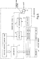
- a modulated radio carrier containing a paging number and message information subsequent thereto is received at an antenna 11.
- the modulated radio carrier received at the antenna 11 is amplified at a receiver section 12, demodulated to a baseband signal and waveform-shaped to a digital signal by a demodulator 13 and sent to a controller 14.
- the controller 14 detects the paging signal and the message signal by performing synchronization, and error correction. Further the controller 14 sets a operational timing for a whole control system and controls a power supply for a radio system.
- the controller 14 compares a received paging number with its own paging number which is preliminarily written in an ID code memory 15 which comprises an electrically erasable programmable read only memory (EEPROM).
- ID code memory 15 comprises an electrically erasable programmable read only memory (EEPROM).
- the controller 14 detects that the call is made against itself. In this case, the controller 14 enables a driver 16 to drive a loud speaker 17 to thereby notify a bearer of receiving the call number and, simultaneously, displays the message information associated therewith on a liquid crystal display (LCD) 18. Further, in order to make the bearer possible to read the message information thereafter, the message information is stored in a message memory of the controller 14.
- a switch 19 generates a trigger signal to stop a function for reporting the call to the bearer and to read the message informations stored in the message memory.
- the paging receiver can change an operation of a calling means against the bearer, for example, temporary stoppage of operational ways of a calling and change of sound volume of the loud speaker 17, by a predetermined manual operation of the switch 19 by the bearer.
- Fig. 2 is a block diagram for explaining the controller of the paging receiver.
- the digital signal composed of a data train containing a paging signal and a message information signal associated therewith, which is demodulated and waveform-shaped by the demodulator 13, is supplied to an input terminal 21 of the controller 14.
- a synchronization signal of the thus input digital signal is derived by a synchronization circuit 22 which synchronizes it in bit and word.
- a battery saving (BS) timing controller 23 controls a operational timing of the whole control system and a power supply for the radio system.
- BS battery saving
- an address check circuit 24 compares the paging number contained in the digital signal with paging numbers stored in the ID code memory 15. If these call numbers are coincident, the address check circuit 24 recognizes the paging number as the call number of the paging receiver, activates a report control circuit 210 and drives the driver 16 according to a reporting format preliminarily set by the bearer. The address check circuit 24 further stores the digitized message signal in a message buffer 23.
- the timer 26 generates a current time by counting clock pulses and sends the current time to the time adder circuit 27 as a current time signal.
- the time adder circuit 27 stamps the message signal with the current time signal from the timer 26 to provide a message signal stamped with current time.
- the message signal stamped with current time is a digital signal having 4 bits per character of message information.
- the message memory 28 stores already received and time stamped message signals.
- the message memory 28 is composed of a S-RAM.
- the comparator 29 compares a received message signal 35 stamped with current time with message signals 1 ⁇ n stamped with receiving times and stored in the message memory 28. The comparison is performed on both content of'the message signal and time attached thereto. When the message signals are coincident and a difference between the receiving times is within a predetermined time, it is decided that the message signal stamped with current time is coincident with the message stamped with received time, and a coincidence signal is sent to the report controller 210.
- the coincidence signal is similar to the trigger signal from the switch 19 shown in Fig. 1 and functions in a similar manner to the control of the report controller 210 by the switch 19.
- the comparison between the message signal stamped with current time and the message signals stamped with received time which have been stored in the message memory 28, which is performed by the comparator 29, includes message signal comparison and receiving time comparison.
- the messages the compared by a comparator 31 of the comparator 29 and the comparator 31 sends the comparison signal to an AND gates 35.
- the first time comparison between current time and stored receiving time is performed by a subtracter 32 and the subtracter sends a time difference signal to a comparator 33.
- the comparator 33 sends a coincidence signal to an AND gate 35 when the time difference signal is smaller than a predetermined value supplied from a fixed value circuit 34.
- the AND gate produces an alert signal when the contents of the message signal and time of the current time signal coincides with those of the received message signal stored in the memory.
- a receiving buffer 25 outputs the message signal to the time adder circuit 27 on the basis of the timing control of the BS timing controller 23. Simultanesouly therewith, the timer 26 sends the current time signal to the time adder circuit 27. Timings of all of subsequent operations are controlled by the BS timing controller 23.
- the time adder circuit 27 attaches the message signal to the current time signal input thereto and sends the message signal stamped with the current time to the comparator 29.
- the comparator 29 reads out the message signals stamped with received time stored in the message memory 28 one by one and compares it with the message signal stamped with the current time.
- the report controller 210 controls the system such that the emergency report can be noted by the bearer by, for example, maximizing volume of the sound from the loud speaker 17 through the driver 16. It is, of course, possible to use other means for notifying the emergency report to the bearer than the sound volume control.
- the comparator 29 controls the system such that the message signal stamped with the current time is overwritten on the coincident message signal stamped with received time in the message memory 28.
- the comparator 29 newly stores the message signal with the current time in the message memory 28.
- controller 14 of the present inventive paging receiver is represented in a hardwared logic circuitry including the address check circuit 24, the buffer 25, the BS timing controller 23 and the synchronization circuit 22, it can be realized in a software. In the latter case, the controller 14 may be realized by using a microprocessor ⁇ PD75308 available from NEC Corporation.
- Fig. 4 is a flowchart showing a sequence operation of a paging receiver according to a second embodiment of the present invention and describing a sequence operation of a message signal stamped with current time when it is coincident with a message in the message memory as a result of address check.
- a message stamped with current time is input to a microprocessor in the step 41, a comparison between messages stamped with time which were previously received by the paging receiver and stored in a message memory thereof and a message stamped with current time is performed in the steps 42 to 45.
- "Left message" in the step 42 means any message stamped with received time which is stored in the message memory and is not searched and compared as yet.
- the message stamped with current time is processed as a normal message in the step 47.
- the message memory is searched in the step 44 to check whether or not the message timer has completed its count.
- the message timer is a timer which is set to a certain count value indicative of the predetermined time period during the message signal processing and can determine the time from signal reception by down-counting the count value in real time.
- the message timer When the message timer has counted to zero, the next received message signal is processed without generating an emergency alert. If the message timer has not completed its count, the message signal in the message memory is checked in the step 45 and, when it is inconsistent with the message stamped with current time, a further message signal in the message memory is searched and compared. When the message timer has not counted-out in the step 44 and the message signal stamped with current time is coincident with a message signal in the message memory in the step 45, the message signal stamped with current time is processed in the step 46 as an emergency message.
- the message timer is newly set to the count value in the step 48 and the received message signal is stored in the message memory in the step 49.
- the microprocessor completes the series of processes after the reception of the message signal stamped with current time.
- Fig. 5 is a flowchart showing an operation sequence of a paging receiver according to a third embodiment of the present invention and describing a sequence operation of a controller thereof after a message signal stamped with current time is input to a microprocessor as in Fig. 4.
- a message signal stamped with current time is input to a microprocessor in the step 41, it is determined in the step 52 whether or not the input message signal is one called repeatedly, that is, whether or not it is identical to a message stored in the message memory. If no, the input message is processed as a normal message in the step 54. If yes, it is determined whether or not the message timer has counted-out in the step 53, as in the second embodiment shown in Fig. 4.
- the input message signal is processed normally in the step 55 as a repeated message.
- the processing of the repeated message may include attachment of a symbol to the message which is indicative of that an identical message was received twice. Further, in order to use a message area of the message memory efficiently, a message signal stamped with current time signal is overwritten in the message memory.
- the message is processed in the step 56 as an emergency message.
- the subsequent steps 48, 49, and 410 are the same as those in the second embodiment shown in Fig. 4.
- Fig. 6 is a flowchart showing an operation sequence of a paging receiver according to a fourth embodiment of the present invention. Since the fourth embodiment is very similar to the third embodiment shown in Fig. 5, only a difference thereof from the third embodiment will be described.
- Conditions for emergency or urgent paging processing include a condition that a message signal is determined as being related to an unverified paging in the step 64, in addition to the condition that a message is a repeated message (step 52) and the condition that the message timer does not count-out (step 53).
- the unverified paging includes a paging which is not reported to the bearer for a reason that, although a radio signal is received by the paging receiver, the receiver is processing another signal. It also includes a paging which, although the microprocessor performed a paging processing, the bearer had not reset the paging mode of the receiver to its auto-reset mode.
- the paging control system of the present invention can be applied to not only the paging receiver but also, for example, a radio telephone or other telephone receiver. In the latter case, it is possible to have a communication between a sender who desires to have an emergency communication with a receiver who is under communication with another, when the sender dials the receiver repeatedly.
- the paging receiver of the present invention is a preferable example of application of the paging control system of the present invention.
- the paging receiver according to the present invention does not require a second call number when an urgent or emergency message should be sent to a bearer. Therefore, it is unnecessary for a sender to have a normal call number and an urgent call number and selectively use them. That is, when a sender has an emergency call to a bearer, it is enough to dial the normal call number of the bearer twice. Further, since the paging receiver does process not all of repeatedly received message information but only a message which is repeatedly received within a predetermined time as an emergency information message, it is possible to urgently report a real emergency call, disregarding a repeated call whose degree of emergency is low.
Landscapes
- Physics & Mathematics (AREA)
- Engineering & Computer Science (AREA)
- Computer Networks & Wireless Communication (AREA)
- Electromagnetism (AREA)
- General Physics & Mathematics (AREA)
- Mobile Radio Communication Systems (AREA)
Applications Claiming Priority (3)
| Application Number | Priority Date | Filing Date | Title |
|---|---|---|---|
| JP12621/93 | 1993-01-28 | ||
| JP5012621A JP2531074B2 (ja) | 1993-01-28 | 1993-01-28 | 無線選択呼出受信機 |
| JP1262193 | 1993-01-28 |
Publications (2)
| Publication Number | Publication Date |
|---|---|
| EP0609102A1 true EP0609102A1 (fr) | 1994-08-03 |
| EP0609102B1 EP0609102B1 (fr) | 1999-10-06 |
Family
ID=11810453
Family Applications (1)
| Application Number | Title | Priority Date | Filing Date |
|---|---|---|---|
| EP94300671A Expired - Lifetime EP0609102B1 (fr) | 1993-01-28 | 1994-01-28 | Récepteur d'appel utile pour un appel de détresse |
Country Status (7)
| Country | Link |
|---|---|
| US (1) | US5493285A (fr) |
| EP (1) | EP0609102B1 (fr) |
| JP (1) | JP2531074B2 (fr) |
| KR (1) | KR960012958B1 (fr) |
| CN (1) | CN1040057C (fr) |
| DE (1) | DE69420986T2 (fr) |
| TW (1) | TW230859B (fr) |
Cited By (2)
| Publication number | Priority date | Publication date | Assignee | Title |
|---|---|---|---|---|
| EP0831439A1 (fr) * | 1996-09-18 | 1998-03-25 | Nec Corporation | Récepteur d'appels sélectifs sans fils |
| US5774061A (en) * | 1995-06-06 | 1998-06-30 | Nec Corporation | Radio selective calling receiver with message display capability |
Families Citing this family (17)
| Publication number | Priority date | Publication date | Assignee | Title |
|---|---|---|---|---|
| JP3467330B2 (ja) * | 1994-09-22 | 2003-11-17 | 富士通株式会社 | システム異常監視装置 |
| JP3666672B2 (ja) * | 1994-12-19 | 2005-06-29 | ソニー株式会社 | 通信端末装置 |
| GB2297884B (en) * | 1995-02-07 | 1999-05-26 | Nokia Mobile Phones Ltd | Radio telephone |
| US5749045A (en) * | 1995-06-29 | 1998-05-05 | Glenayre Electronics, Inc. | Method for handling alarm conditions in a paging system |
| US5799023A (en) * | 1995-07-19 | 1998-08-25 | Matsushita Electric Industrial Co., Ltd. | Message receiver |
| JPH1013899A (ja) * | 1996-06-21 | 1998-01-16 | Nec Shizuoka Ltd | 無線選択呼出受信機 |
| US6112074A (en) * | 1997-12-22 | 2000-08-29 | Motorola, Inc. | Radio communication system with automatic geographic event notification |
| JP3723422B2 (ja) * | 2000-07-11 | 2005-12-07 | 三洋電機株式会社 | 携帯端末機 |
| JP2003037875A (ja) * | 2001-05-16 | 2003-02-07 | Sony Computer Entertainment Inc | メッセージ送受信方法、メッセージ送信方法、メッセージ受信方法、コンピュータに実行させるためのメッセージ送信プログラムを記憶したコンピュータ読み取り可能な記憶媒体、コンピュータに実行させるためのメッセージ受信プログラムを記憶したコンピュータ読み取り可能な記憶媒体、送信機、受信機、送受信機、メッセージ送受信システム、コンピュータに実行させるためのメッセージ送信プログラム、及びコンピュータに実行させるためのメッセージ受信プログラム |
| US6560454B2 (en) * | 2001-05-30 | 2003-05-06 | Nokia Corp. | System and method for delivery and updating of data transmitted to a mobile terminal |
| US7190947B2 (en) * | 2003-02-07 | 2007-03-13 | Motorola Inc. | Priority E911 call back during access class restrictions |
| US8942728B2 (en) * | 2004-05-03 | 2015-01-27 | Qualcomm Incorporated | Methods and apparatus for blackout, retune and subscription enforcement in a cellular network multimedia distribution system |
| WO2010070429A1 (fr) * | 2008-12-17 | 2010-06-24 | Telefonaktiebolaget Lm Ericsson (Publ) | Segmentation et réassemblage de messages d'avertissement |
| EP2410340B1 (fr) | 2009-03-18 | 2019-06-26 | Sysmex Corporation | Analyseur d'échantillon |
| CN102137490B (zh) * | 2010-01-27 | 2015-05-20 | 京东方科技集团股份有限公司 | 便携式无线寻呼机、接收机、系统及方法 |
| US9295086B2 (en) | 2013-08-30 | 2016-03-22 | Motorola Solutions, Inc. | Method for operating a radio communication device in a multi-watch mode |
| EP3362819A4 (fr) * | 2015-10-14 | 2019-06-05 | Shenzhen Xpectvision Technology Co., Ltd. | Détecteurs de rayons x aptes à limiter la diffusion de porteurs de charge |
Citations (4)
| Publication number | Priority date | Publication date | Assignee | Title |
|---|---|---|---|---|
| US4438433A (en) * | 1981-09-29 | 1984-03-20 | Motorola, Inc. | Multiaddress pager with a call storage and priority paging option |
| US4786901A (en) * | 1984-03-13 | 1988-11-22 | Nec Corporation | Paging receiver |
| US4949085A (en) * | 1987-06-30 | 1990-08-14 | Motorola, Inc. | Prioritization of stored messages in a digital voice paging receiver |
| EP0497578A2 (fr) * | 1991-01-29 | 1992-08-05 | Nec Corporation | Procédé et dispositif pour mémoriser l'instant de réception d'un message et détecter le rappel d'un message dans un récepteur d'appel radio |
Family Cites Families (12)
| Publication number | Priority date | Publication date | Assignee | Title |
|---|---|---|---|---|
| JPS5932232A (ja) * | 1982-08-17 | 1984-02-21 | Nec Corp | 表示機能付無線選択呼出受信機 |
| US4701759A (en) * | 1984-04-03 | 1987-10-20 | Motorola, Inc. | Call reminder for a radio paging device |
| US4713808A (en) * | 1985-11-27 | 1987-12-15 | A T & E Corporation | Watch pager system and communication protocol |
| JPS62160830A (ja) * | 1986-01-10 | 1987-07-16 | Nec Corp | 選択呼出信号受信機 |
| US4835777A (en) * | 1987-01-07 | 1989-05-30 | Motorola, Inc. | Radio paging receiver including duplicate page detection and error correction capability |
| US4872005A (en) * | 1988-01-04 | 1989-10-03 | Motorola, Inc. | Paging receiver capable of reminding a user of an important message event |
| US4894649A (en) * | 1988-01-07 | 1990-01-16 | Motorola, Inc. | Pager having time controlled functions |
| JPH025634A (ja) * | 1988-06-24 | 1990-01-10 | Toshiba Corp | 選択呼出受信機 |
| US5012219A (en) * | 1989-10-13 | 1991-04-30 | Motorola, Inc. | Message reminder alert for selective call receiver |
| JPH0457939U (fr) * | 1990-09-25 | 1992-05-19 | ||
| US5347269A (en) * | 1992-05-08 | 1994-09-13 | Motorola, Inc. | Iconic duplicate message indicator |
| US5384565A (en) * | 1992-08-03 | 1995-01-24 | Motorola, Inc. | Method and apparatus for identifying duplicate data messages in a communication system |
-
1993
- 1993-01-28 JP JP5012621A patent/JP2531074B2/ja not_active Expired - Fee Related
-
1994
- 1994-01-27 US US08/188,147 patent/US5493285A/en not_active Expired - Fee Related
- 1994-01-28 KR KR1019940001547A patent/KR960012958B1/ko not_active Expired - Fee Related
- 1994-01-28 TW TW083100733A patent/TW230859B/zh active
- 1994-01-28 DE DE69420986T patent/DE69420986T2/de not_active Expired - Fee Related
- 1994-01-28 CN CN94102621A patent/CN1040057C/zh not_active Expired - Fee Related
- 1994-01-28 EP EP94300671A patent/EP0609102B1/fr not_active Expired - Lifetime
Patent Citations (4)
| Publication number | Priority date | Publication date | Assignee | Title |
|---|---|---|---|---|
| US4438433A (en) * | 1981-09-29 | 1984-03-20 | Motorola, Inc. | Multiaddress pager with a call storage and priority paging option |
| US4786901A (en) * | 1984-03-13 | 1988-11-22 | Nec Corporation | Paging receiver |
| US4949085A (en) * | 1987-06-30 | 1990-08-14 | Motorola, Inc. | Prioritization of stored messages in a digital voice paging receiver |
| EP0497578A2 (fr) * | 1991-01-29 | 1992-08-05 | Nec Corporation | Procédé et dispositif pour mémoriser l'instant de réception d'un message et détecter le rappel d'un message dans un récepteur d'appel radio |
Cited By (2)
| Publication number | Priority date | Publication date | Assignee | Title |
|---|---|---|---|---|
| US5774061A (en) * | 1995-06-06 | 1998-06-30 | Nec Corporation | Radio selective calling receiver with message display capability |
| EP0831439A1 (fr) * | 1996-09-18 | 1998-03-25 | Nec Corporation | Récepteur d'appels sélectifs sans fils |
Also Published As
| Publication number | Publication date |
|---|---|
| JP2531074B2 (ja) | 1996-09-04 |
| KR940019093A (ko) | 1994-08-19 |
| TW230859B (fr) | 1994-09-21 |
| EP0609102B1 (fr) | 1999-10-06 |
| DE69420986D1 (de) | 1999-11-11 |
| CN1094200A (zh) | 1994-10-26 |
| CN1040057C (zh) | 1998-09-30 |
| DE69420986T2 (de) | 2000-01-20 |
| KR960012958B1 (ko) | 1996-09-25 |
| JPH06224823A (ja) | 1994-08-12 |
| US5493285A (en) | 1996-02-20 |
Similar Documents
| Publication | Publication Date | Title |
|---|---|---|
| EP0609102B1 (fr) | Récepteur d'appel utile pour un appel de détresse | |
| KR940001431B1 (ko) | 무선호출 시스템 | |
| EP0135783B1 (fr) | Dispositif de radio-communication désactivé par réception d'un signal prédéterminé | |
| JPH0412052B2 (fr) | ||
| JP2990072B2 (ja) | 無線選択呼出受信機 | |
| US4870403A (en) | Paging receiver with a capability of receiving or inhibiting message data | |
| EP0317230A2 (fr) | Appareil d'appel personnel équipé d'un circuit de sélection de message | |
| US5697097A (en) | Method for increasing the endurance of an information receiver, particularly for radio paging, and corresponding receiver | |
| EP0488815A2 (fr) | Récepteur d'appel radio avec affichage de données | |
| EP0308132B1 (fr) | Récepteur d'appel avec une fonction d'affichage | |
| US5960326A (en) | Radio apparatus outputting an alarm prior to a scheduled time | |
| EP0509649B1 (fr) | Récepteur d'appel sélectif | |
| JPH04257127A (ja) | 選択呼出受信機 | |
| US5892456A (en) | Index managing method and apparatus of received messages for a radio paging receiver | |
| GB2352938A (en) | Communication apparatus and method of displaying images | |
| JP2659558B2 (ja) | 選択無線呼出方式 | |
| JP2890929B2 (ja) | 無線選択呼出受信機 | |
| US20020034955A1 (en) | Selective radio paging receiver | |
| JP2806896B2 (ja) | 無線選択呼出受信機 | |
| JP2935037B2 (ja) | 呼出検出装置 | |
| JPH0693646B2 (ja) | 無線選択呼出受信機 | |
| KR100247188B1 (ko) | 무선 호출 수신기의 동일메시지 처리 방법 | |
| US5485146A (en) | Paging receiver | |
| KR100282245B1 (ko) | 무선 호출 수신기와 무선 수신기 | |
| US6294979B1 (en) | Radio paging receiver and radio receiver |
Legal Events
| Date | Code | Title | Description |
|---|---|---|---|
| PUAI | Public reference made under article 153(3) epc to a published international application that has entered the european phase |
Free format text: ORIGINAL CODE: 0009012 |
|
| 17P | Request for examination filed |
Effective date: 19940602 |
|
| AK | Designated contracting states |
Kind code of ref document: A1 Designated state(s): DE GB NL SE |
|
| 17Q | First examination report despatched |
Effective date: 19970919 |
|
| GRAG | Despatch of communication of intention to grant |
Free format text: ORIGINAL CODE: EPIDOS AGRA |
|
| GRAG | Despatch of communication of intention to grant |
Free format text: ORIGINAL CODE: EPIDOS AGRA |
|
| GRAG | Despatch of communication of intention to grant |
Free format text: ORIGINAL CODE: EPIDOS AGRA |
|
| GRAH | Despatch of communication of intention to grant a patent |
Free format text: ORIGINAL CODE: EPIDOS IGRA |
|
| GRAH | Despatch of communication of intention to grant a patent |
Free format text: ORIGINAL CODE: EPIDOS IGRA |
|
| GRAA | (expected) grant |
Free format text: ORIGINAL CODE: 0009210 |
|
| AK | Designated contracting states |
Kind code of ref document: B1 Designated state(s): DE GB NL SE |
|
| REF | Corresponds to: |
Ref document number: 69420986 Country of ref document: DE Date of ref document: 19991111 |
|
| PLBE | No opposition filed within time limit |
Free format text: ORIGINAL CODE: 0009261 |
|
| STAA | Information on the status of an ep patent application or granted ep patent |
Free format text: STATUS: NO OPPOSITION FILED WITHIN TIME LIMIT |
|
| 26N | No opposition filed | ||
| PGFP | Annual fee paid to national office [announced via postgrant information from national office to epo] |
Ref country code: NL Payment date: 20010131 Year of fee payment: 8 |
|
| REG | Reference to a national code |
Ref country code: GB Ref legal event code: IF02 |
|
| PG25 | Lapsed in a contracting state [announced via postgrant information from national office to epo] |
Ref country code: NL Free format text: LAPSE BECAUSE OF NON-PAYMENT OF DUE FEES Effective date: 20020801 |
|
| NLV4 | Nl: lapsed or anulled due to non-payment of the annual fee |
Effective date: 20020801 |
|
| PGFP | Annual fee paid to national office [announced via postgrant information from national office to epo] |
Ref country code: SE Payment date: 20050107 Year of fee payment: 12 |
|
| PGFP | Annual fee paid to national office [announced via postgrant information from national office to epo] |
Ref country code: DE Payment date: 20050120 Year of fee payment: 12 |
|
| PGFP | Annual fee paid to national office [announced via postgrant information from national office to epo] |
Ref country code: GB Payment date: 20050126 Year of fee payment: 12 |
|
| PG25 | Lapsed in a contracting state [announced via postgrant information from national office to epo] |
Ref country code: GB Free format text: LAPSE BECAUSE OF NON-PAYMENT OF DUE FEES Effective date: 20060128 |
|
| PG25 | Lapsed in a contracting state [announced via postgrant information from national office to epo] |
Ref country code: SE Free format text: LAPSE BECAUSE OF NON-PAYMENT OF DUE FEES Effective date: 20060129 |
|
| PG25 | Lapsed in a contracting state [announced via postgrant information from national office to epo] |
Ref country code: DE Free format text: LAPSE BECAUSE OF NON-PAYMENT OF DUE FEES Effective date: 20060801 |
|
| EUG | Se: european patent has lapsed | ||
| GBPC | Gb: european patent ceased through non-payment of renewal fee |
Effective date: 20060128 |