EP0609103B1 - Antenne pour appareil de communication en forme d'appareil radio portable - Google Patents
Antenne pour appareil de communication en forme d'appareil radio portable Download PDFInfo
- Publication number
- EP0609103B1 EP0609103B1 EP94300673A EP94300673A EP0609103B1 EP 0609103 B1 EP0609103 B1 EP 0609103B1 EP 94300673 A EP94300673 A EP 94300673A EP 94300673 A EP94300673 A EP 94300673A EP 0609103 B1 EP0609103 B1 EP 0609103B1
- Authority
- EP
- European Patent Office
- Prior art keywords
- antenna
- conductor
- casing
- retracted
- matching circuit
- Prior art date
- Legal status (The legal status is an assumption and is not a legal conclusion. Google has not performed a legal analysis and makes no representation as to the accuracy of the status listed.)
- Expired - Lifetime
Links
- 239000004020 conductor Substances 0.000 claims description 70
- 239000012212 insulator Substances 0.000 claims description 8
- 230000008878 coupling Effects 0.000 claims description 4
- 238000010168 coupling process Methods 0.000 claims description 4
- 238000005859 coupling reaction Methods 0.000 claims description 4
- 230000005855 radiation Effects 0.000 description 3
- 239000003990 capacitor Substances 0.000 description 1
- 230000000593 degrading effect Effects 0.000 description 1
- 238000005259 measurement Methods 0.000 description 1
- 238000012986 modification Methods 0.000 description 1
- 230000004048 modification Effects 0.000 description 1
- 229920003002 synthetic resin Polymers 0.000 description 1
- 239000000057 synthetic resin Substances 0.000 description 1
Images



Classifications
-
- H—ELECTRICITY
- H01—ELECTRIC ELEMENTS
- H01Q—ANTENNAS, i.e. RADIO AERIALS
- H01Q1/00—Details of, or arrangements associated with, antennas
- H01Q1/08—Means for collapsing antennas or parts thereof
- H01Q1/10—Telescopic elements
-
- H—ELECTRICITY
- H01—ELECTRIC ELEMENTS
- H01Q—ANTENNAS, i.e. RADIO AERIALS
- H01Q1/00—Details of, or arrangements associated with, antennas
- H01Q1/12—Supports; Mounting means
- H01Q1/22—Supports; Mounting means by structural association with other equipment or articles
- H01Q1/24—Supports; Mounting means by structural association with other equipment or articles with receiving set
- H01Q1/241—Supports; Mounting means by structural association with other equipment or articles with receiving set used in mobile communications, e.g. GSM
- H01Q1/242—Supports; Mounting means by structural association with other equipment or articles with receiving set used in mobile communications, e.g. GSM specially adapted for hand-held use
- H01Q1/243—Supports; Mounting means by structural association with other equipment or articles with receiving set used in mobile communications, e.g. GSM specially adapted for hand-held use with built-in antennas
Definitions
- the present invention relates to an antenna mounted on and retractable into the casing of a portable radio communication apparatus and, more particularly, to an antenna having a sufficient gain even when retracted into the casing.
- Japanese Utility Model Laid-Open Publication No. 61-57608 teaches a rod antenna having a coil-like portion at the tip thereof, and a cover made of synthetic resin and covering the coil-like portion.
- the problem with this kind of antenna is that when it is applied to a portable radio communication apparatus and received in the casing of the apparatus, it cannot have the same gain as when pulled out of the casing.
- EP-A-0.522.806 describes an antenna system in which a single antenna element takes a first position in which it is extended from the housing and in contact with a first feed terminal and a second position in which it is retracted into the housing and in contact with a second feed terminal. Automatic switching of the feed terminals ensures that the antenna system is fed with a matched condition in both the first and second position of the antenna element.
- Another object of the preferred embodiment is to provide a compact antenna which has performance approximating to that of a ⁇ /2 whip antenna.
- the invention provides an antenna mounted on and retractable into a casing of a portable radio communication apparatus, comprising:
- the invention provides a portable radio communication apparatus comprising:
- the means coupling the antenna to the matching circuit comprises a component having a bore through which the second conductor passes, and which is electrically insulated therefrom.
- the apparatus has a casing 52 on which a metallic retainer 53 is fixed in place.
- a whip antenna 51 is held by the retainer 53 and is movable into the casing 52, a s desired.
- a matching circuit 54 feeds the whip antenna 51 via the metallic retainer 53.
- the matching circuit 54 is used to match the input impedance of the whip antenna 51, which is as high as several hundred ohms, to the feed ratio (generally, characteristic impedance of 50 ohms).
- FIG. 6 shows an equivalent circuit representative of the matching circuit 54.
- capacitors having lumped constants or stray capacities C 1 and C 2 between the terminals and the casing 52, and a coil of conductor or pattern L formed on a printed circuit board.
- the problem with the conventional apparatus is that the gain is noticeably lowered when the whip antenna 51 is received in the casing 52. Therefore, when the user of the apparatus carries it while waiting for a call, the antenna 51 has to be maintained in the extended position.
- an antenna embodying the present invention will be described. As shown, an antenna 1 is mounted on a casing 10 included in a portable radio communication apparatus. The antenna 1 is retractable into the casing 10, as desired.
- the antenna 1 is made up of a first conductor 2 having a length L 1 , an insulator 3 covering the first conductor 2, a second conductor 4 having a length L 2 and implemented by a hollow rod-like conductor for receiving the conductor 2 enclosed by the insulator 3, an insulator 5 covering the second conductor 4, and a connection conductor 6 fitted on the lower end of the conductor 2 for maintaining the conductors 2 and 4 in contact.
- a cover member 7 is made of an insulator or a conductor and formed on the tip or upper end of the antenna 1. When the antenna 1 is received in the casing 10, the cover member 7 causes a part of the first conductor 1 to remain exposed to the outside of the casing 10 over a length L 3 .
- the cover member 7 has a diameter greater than the diameter of the second conductor 4, so that it will not enter the casing 10 when the antenna 1 is retracted into the casing 10.
- a metallic retainer 8 is provided on the lower end portion or root portion of the second conductor 4 in order to affix the antenna 1 to the casing 10 and to feed the antenna 1.
- a matching circuit 9 and a metallic part for grounding 11 are accommodated in the casing 10.
- the matching circuit 9 feeds the antenna 1 via the retainer 8.
- the metallic part 11 contacts the lower end of the second conductor 4 to connect it to ground.
- the matching circuit 9 feeds the antenna 1 via the retainer 8.
- FIG. 1B when the antenna is received in the casing 10, only a part of the first conductor 2 which is enclosed by the insulative or conductive cover member 7 is left outside of the casing 10. At this instant, the lower end of the second conductor 4 is connected to ground via the metallic part 11.
- the length L of the antenna 1 is selected to be about ⁇ / 2 when the antenna 1 is extended. Hence, in the extended position, the antenna 1 serves as a ⁇ /2 whip antenna.
- the part of the antenna 1 enclosed by the cover member 7 and left outside of the casing 10 over the length L 3 plays the role of an antenna.
- the upper end of the second conductor 4 and the retainer 8 are connected with respect to high frequency and fed, even the part of the antenna 1 received in the casing 10 is driven and contributes to the antenna characteristic. Presumably, this is derived from the following occurrence.
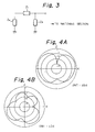
- FIG. 3 shows an equivalent circuit presumably representative of the antenna 1 received in the casing 10.
- the circuit includes an impedance Z a particular to the upper end of the first conductor 2 and equal to the impedance of a whip antenna having a length L 3 . Since the first conductor 2 is covered with the insulator 3, it does not contact the second conductor 4, although it is short-circuited by the connection conductor 6 in the retracted position of the antenna 1. Hence, a coaxial structure whose one end is short-circuited by the conductors 2 and 4 is set up. This coaxial structural portion has an impedance Z 1 . An impedance Z 2 is set up when the lower end of the second conductor 4 is connected to ground via the metallic part 11. Such an antenna system is connected to a feed section via the matching circuit 9.
- the impedance Z a Since the length L 3 in the retracted position of the antenna 1 is selected to be as small as possible, the impedance Z a exhibits a capacitance which is small in an actual portion (resistance) and great in an imaginary portion (reactance), compared to a ⁇ /2 whip antenna. Therefore, when the lengths L 1 and L 2 of the first and second conductors 2 and 4, respectively, are changed, the impedances Z 1 and Z 2 change. It follows that by adequately selecting the lengths L 1 and L 2 , it is possible to convert the impedance Z a to a value substantially equal to the antenna impedance in the extended position. As a result, a single matching circuit 9 suffices for both of the extended and retracted positions of the antenna 1, i.e., substantially the same gain is achievable in both of the extended and retracted positions.
- FIGS. 4A and 4B show radiation patterns occurred when the antenna 1 was extended and retracted, respectively.
- the frequency for measurement was 935 MHz.
- the two radiation patterns shown in FIGS. 4A and 4B are different from each other since a current flows to both the antenna 1 and the casing 10 in the retracted position, but it mainly flows to the antenna 1 in the extended position.
- the peak value of the gain in the retracted position is only about 3 dB lower than the peak value in the extended position. This indicates that the antenna 1 has an excellent characteristic.
- the second conductor 4 may be replaced with a spiral conductive coil turned without any gap.
- the conductive coil not only achieves the above-stated characteristic but also provides the antenna 1 with flexibility, which is desirable from the damage standpoint.
- the spiral conductor constituting the second conductor 4 may be provided with a gap in a part thereof so as to increase the inductance, in which case the length of the conductor 4 will be reduced in matching relation to the gap.
- the insulator 5 associated with the second conductor 4 is omissible since it mainly serves to provide the antenna 1 with attractive appearance.
- the present invention provides an antenna which plays the role of a ⁇ /2 whip antenna when extended and has substantially the same gain both in the extended and retracted positions thereof. Furthermore, when a second conductor included in the antenna is implemented as a coil, it provides the antenna with flexibility.
Landscapes
- Engineering & Computer Science (AREA)
- Computer Networks & Wireless Communication (AREA)
- Support Of Aerials (AREA)
- Details Of Aerials (AREA)
- Transceivers (AREA)
Claims (9)
- Antenne (1) montée sur et pouvant être rétractée dans un boítier (10) d'un appareil de communication en forme d'appareil radio portable, comprenant :un premier conducteur (2) ;un second conducteur tubulaire (4) afin de recevoir ledit premier conducteur ;des moyens (7) pour assurer que lorsque l'antenne (1) est rétractée dans le boítier (10), une partie d'extrémité du premier conducteur (2) d'une longueur prédéterminée reste à l'extérieur du boítier (10) ; etune partie de mise à la masse métallique (11) pour entrer en contact avec l'extrémité inférieure dudit second conducteur (4) lorsque ladite antenne (1) est rétractée dans ledit boítier (10) ; caractérisée en ce queledit premier conducteur (2) est recouvert d'un isolant (3) ;ledit second conducteur (4) est rétractable dans le boítier (10) ; etladite antenne comprend en outre un conducteur à connexion (6) monté sur l'extrémité inférieure dudit premier conducteur (2) afin de maintenir en contact permanent ledit premier conducteur (2) et ledit conducteur (4).
- Antenne selon la revendication 1, dans laquelle lesdits moyens pour assurer sont un élément formant couvercle (7) recouvrant une partie d'extrémité dudit premier conducteur (2) sur ladite longueur prédéterminée et ayant un diamètre supérieur à celui dudit second conducteur (4).
- Appareil de communication en forme d'appareil radio portable comprenant :un boítier (10)une antenne (1) selon la revendication 1 ou 2 ;un circuit d'adaptation (9) ; etdes moyens (8) couplant l'antenne (1) au circuit d'adaptation (9) ;dans laquelle, lorsque l'antenne (1) est rétractée dans le boítier (10), l'impédance de la partie d'extrémité du premier conducteur (2) comme représenté par le circuit d'adaptation (9), est convertie par l'impédance entre le reste du premier conducteur (2) et le second conducteur (4) et entre l'antenne (1) et la masse du circuit en une valeur proche de celle d'une antenne λ/2 à la fréquence de fonctionnement de l'appareil.
- Appareil selon la revendication 3, dans lequel les premier et second conducteurs (2, 4) peuvent s'étendre au-delà du boítier pour former une antenne λ/2.
- Appareil selon la revendication 3 ou 4, dans lequel les moyens (8) couplant l'antenne (1) au circuit d'adaptation (10) comprennent un composant comportant un alésage à travers lequel passe le second conducteur (4), et qui est isolé électriquement de celui-ci.
- Antenne ou appareil selon l'une quelconque des revendications précédentes, dans laquelle ou lequel ledit second conducteur (4) comprend un conducteur en forme de tige creuse.
- Antenne ou appareil selon l'une quelconque des revendications 1 à 5, dans laquelle ou lequel ledit second conducteur (4) comprend une bobine conductrice spiralée sans espacement entre ses spires adjacentes.
- Antenne ou appareil selon l'une quelconque des revendications 1 à 5, dans laquelle ou lequel ledit second conducteur (4) comprend une bobine spiralée conductrice ayant un espacement entre des spires adjacentes sur une partie de celle-ci.
- Antenne ou appareil selon l'une quelconque des revendications précédentes, dans laquelle ou lequel les premier et second conducteurs (2, 4) sont approximativement de la même longueur.
Applications Claiming Priority (2)
| Application Number | Priority Date | Filing Date | Title |
|---|---|---|---|
| JP34252/93 | 1993-01-29 | ||
| JP5034252A JP2503856B2 (ja) | 1993-01-29 | 1993-01-29 | 携帯無線機用アンテナ |
Publications (2)
| Publication Number | Publication Date |
|---|---|
| EP0609103A1 EP0609103A1 (fr) | 1994-08-03 |
| EP0609103B1 true EP0609103B1 (fr) | 1998-08-19 |
Family
ID=12408984
Family Applications (1)
| Application Number | Title | Priority Date | Filing Date |
|---|---|---|---|
| EP94300673A Expired - Lifetime EP0609103B1 (fr) | 1993-01-29 | 1994-01-28 | Antenne pour appareil de communication en forme d'appareil radio portable |
Country Status (6)
| Country | Link |
|---|---|
| US (1) | US5455595A (fr) |
| EP (1) | EP0609103B1 (fr) |
| JP (1) | JP2503856B2 (fr) |
| AU (1) | AU668261B2 (fr) |
| CA (1) | CA2114458C (fr) |
| DE (1) | DE69412524T2 (fr) |
Families Citing this family (21)
| Publication number | Priority date | Publication date | Assignee | Title |
|---|---|---|---|---|
| KR960030478A (ko) * | 1995-01-27 | 1996-08-17 | 김광호 | 무선기기의 안테나 |
| KR100194422B1 (ko) * | 1995-04-27 | 1999-06-15 | 김광호 | 휴대용 무선기기의 안테나 접속장치 |
| US5635943A (en) * | 1995-10-16 | 1997-06-03 | Matsushita Communication Industrial Corp. Of America | Transceiver having retractable antenna assembly |
| US5717408A (en) * | 1995-12-18 | 1998-02-10 | Centurion International, Inc. | Retractable antenna for a cellular telephone |
| DE19548822A1 (de) * | 1995-12-27 | 1997-07-03 | Mobil Und Satellitenfunktechni | Mobilfunk-Antennenvorrichtung |
| JP2692670B2 (ja) * | 1995-12-28 | 1997-12-17 | 日本電気株式会社 | 携帯無線機用アンテナ |
| US5748150A (en) * | 1996-04-04 | 1998-05-05 | Ericsson, Inc. | Retractable antenna assembly |
| US5900846A (en) * | 1996-08-21 | 1999-05-04 | Ericsson, Inc. | Flexible telescoping antenna and method of constructing the same |
| US5969684A (en) * | 1998-05-13 | 1999-10-19 | Ace Technology Co., Ltd. | Capacitive coupled extendable antenna for portable communication devices |
| KR100299026B1 (ko) * | 1998-09-11 | 2001-09-22 | 윤종용 | 신장가능한소형안테나 |
| US6191741B1 (en) * | 1998-11-06 | 2001-02-20 | Sierra Wireless, Inc. | Dual mode antenna for personal computer card |
| US6198443B1 (en) | 1999-07-30 | 2001-03-06 | Centurion Intl., Inc. | Dual band antenna for cellular communications |
| US6417808B1 (en) | 2000-03-07 | 2002-07-09 | Nec Corporation | Transceiver including antenna apparatus which is compactly accommodated in body of transceiver |
| KR100442453B1 (ko) * | 2001-10-31 | 2004-07-30 | 김영준 | 무선통신용 앤엑스 안테나 |
| KR101394268B1 (ko) * | 2007-09-27 | 2014-05-26 | 삼성전자주식회사 | 본체 내부에 추가 안테나 패턴을 구비하고 있는 휴대단말기 |
| JP4822288B2 (ja) * | 2008-03-27 | 2011-11-24 | 株式会社 仲池技研 | ダイポールアンテナ及びこれを用いた無線通信機 |
| US10852373B2 (en) | 2016-09-21 | 2020-12-01 | Quality Electrodynamics, Llc | Modulating magnetic resonance imaging transmit field in magnetic resonance fingerprinting using single layer transmit/receive radio frequency coil |
| US11156682B2 (en) | 2017-03-24 | 2021-10-26 | Quality Electrodynamics, Llc | Single layer magnetic resonance imaging transmit/receive radio frequency coil for different anatomies |
| US10976388B2 (en) * | 2017-03-24 | 2021-04-13 | Quality Electrodynamics, Llc | Minimizing intravascular magnetic resonance imaging (MRI) guidewire heating with single layer MRI transmit/receive radio frequency coil |
| US11193992B2 (en) | 2017-05-05 | 2021-12-07 | Quality Electrodynamics, Llc | Single layer magnetic resonance imaging (MRI) transmit/receive (Tx/Rx) radio frequency (RF) coil with induced current failsafe protection |
| US10838028B2 (en) | 2017-06-19 | 2020-11-17 | Quality Electrodynamics, Llc | Decoupling magnetic resonance imaging (MRI) radio frequency (RF) coil elements with high acceleration factor in parallel transmit (pTx) or receive (Rx) coils using fewer channels |
Family Cites Families (12)
| Publication number | Priority date | Publication date | Assignee | Title |
|---|---|---|---|---|
| US110930A (en) * | 1871-01-10 | Henry millingar | ||
| JPS62120103A (ja) * | 1985-11-20 | 1987-06-01 | Fujitsu Ltd | 自動切換アンテナ |
| JPH01105237U (fr) * | 1987-12-28 | 1989-07-14 | ||
| US4868576A (en) * | 1988-11-02 | 1989-09-19 | Motorola, Inc. | Extendable antenna for portable cellular telephones with ground radiator |
| JPH0316402A (ja) * | 1989-06-14 | 1991-01-24 | Mitsubishi Electric Corp | アンテナ装置 |
| JPH0432305A (ja) * | 1990-05-29 | 1992-02-04 | Nec Corp | アンテナ |
| JP2703670B2 (ja) * | 1991-04-12 | 1998-01-26 | 三菱電機株式会社 | アンテナ装置 |
| JP2575549B2 (ja) * | 1991-05-07 | 1997-01-29 | 富士通株式会社 | 無線端末装置のアンテナ取付構造 |
| DE69215283T2 (de) * | 1991-07-08 | 1997-03-20 | Nippon Telegraph & Telephone | Ausfahrbares Antennensystem |
| GB2257837B (en) * | 1991-07-13 | 1995-10-18 | Technophone Ltd | Retractable antenna |
| GB2257835B (en) * | 1991-07-13 | 1995-10-11 | Technophone Ltd | Retractable antenna |
| JPH066121A (ja) * | 1992-06-19 | 1994-01-14 | Toyo Commun Equip Co Ltd | アンテナ装置 |
-
1993
- 1993-01-29 JP JP5034252A patent/JP2503856B2/ja not_active Expired - Lifetime
-
1994
- 1994-01-26 US US08/186,570 patent/US5455595A/en not_active Expired - Lifetime
- 1994-01-27 AU AU54754/94A patent/AU668261B2/en not_active Ceased
- 1994-01-28 DE DE69412524T patent/DE69412524T2/de not_active Expired - Lifetime
- 1994-01-28 EP EP94300673A patent/EP0609103B1/fr not_active Expired - Lifetime
- 1994-01-28 CA CA002114458A patent/CA2114458C/fr not_active Expired - Fee Related
Also Published As
| Publication number | Publication date |
|---|---|
| CA2114458C (fr) | 1998-09-22 |
| AU668261B2 (en) | 1996-04-26 |
| CA2114458A1 (fr) | 1994-07-30 |
| DE69412524T2 (de) | 1998-12-24 |
| AU5475494A (en) | 1994-08-04 |
| EP0609103A1 (fr) | 1994-08-03 |
| JPH06232614A (ja) | 1994-08-19 |
| DE69412524D1 (de) | 1998-09-24 |
| JP2503856B2 (ja) | 1996-06-05 |
| US5455595A (en) | 1995-10-03 |
Similar Documents
| Publication | Publication Date | Title |
|---|---|---|
| EP0609103B1 (fr) | Antenne pour appareil de communication en forme d'appareil radio portable | |
| US5479178A (en) | Portable radio antenna | |
| JP3406328B2 (ja) | 収縮可能アンテナ | |
| CA2318799C (fr) | Antenne double bande pour equipement radioelectrique terminal | |
| US4958382A (en) | Radio transceiver apparatus for changing over between antennas | |
| JP2764349B2 (ja) | 携帯装置用アンテナ | |
| EP0613206B1 (fr) | Antenne pour un radiotéléphone | |
| US5467097A (en) | Telescoping antenna with dual impedance matching circuits | |
| US5635943A (en) | Transceiver having retractable antenna assembly | |
| IE892800L (en) | Improved extendable antenna for portable cellular telephones | |
| JP3409069B2 (ja) | ワイヤレス通信装置のためのアンテナ・アセンブリ | |
| EP1019979B1 (fr) | Systemes d'adaptation a point d'alimentation unique | |
| US5825330A (en) | Radio antenna | |
| US6097934A (en) | Retractable radiotelephone antennas with extended feeds | |
| GB2257837A (en) | Retractable antenna | |
| EP0718909B1 (fr) | Antenne rétractable à charge en sommet | |
| AU670389B2 (en) | Antenna system having plural antenna portions | |
| US6008765A (en) | Retractable top load antenna | |
| US5926140A (en) | Antenna for portable radio unit | |
| JP3230841B2 (ja) | 可変長ホイップアンテナ | |
| JP3047512B2 (ja) | 携帯無線機のアンテナ構造 | |
| JP2775556B2 (ja) | アンテナ装置 | |
| JP2000151245A (ja) | 携帯無線機およびアンテナ装置 | |
| JPH0360204A (ja) | アンテナ装置 | |
| WO2001069715A1 (fr) | Dispositif d'antenne |
Legal Events
| Date | Code | Title | Description |
|---|---|---|---|
| PUAI | Public reference made under article 153(3) epc to a published international application that has entered the european phase |
Free format text: ORIGINAL CODE: 0009012 |
|
| 17P | Request for examination filed |
Effective date: 19940527 |
|
| AK | Designated contracting states |
Kind code of ref document: A1 Designated state(s): DE FR GB IT SE |
|
| 17Q | First examination report despatched |
Effective date: 19961008 |
|
| GRAG | Despatch of communication of intention to grant |
Free format text: ORIGINAL CODE: EPIDOS AGRA |
|
| GRAG | Despatch of communication of intention to grant |
Free format text: ORIGINAL CODE: EPIDOS AGRA |
|
| GRAH | Despatch of communication of intention to grant a patent |
Free format text: ORIGINAL CODE: EPIDOS IGRA |
|
| GRAH | Despatch of communication of intention to grant a patent |
Free format text: ORIGINAL CODE: EPIDOS IGRA |
|
| GRAH | Despatch of communication of intention to grant a patent |
Free format text: ORIGINAL CODE: EPIDOS IGRA |
|
| GRAA | (expected) grant |
Free format text: ORIGINAL CODE: 0009210 |
|
| AK | Designated contracting states |
Kind code of ref document: B1 Designated state(s): DE FR GB IT SE |
|
| REF | Corresponds to: |
Ref document number: 69412524 Country of ref document: DE Date of ref document: 19980924 |
|
| ET | Fr: translation filed | ||
| PLBE | No opposition filed within time limit |
Free format text: ORIGINAL CODE: 0009261 |
|
| STAA | Information on the status of an ep patent application or granted ep patent |
Free format text: STATUS: NO OPPOSITION FILED WITHIN TIME LIMIT |
|
| 26N | No opposition filed | ||
| REG | Reference to a national code |
Ref country code: GB Ref legal event code: IF02 |
|
| PGFP | Annual fee paid to national office [announced via postgrant information from national office to epo] |
Ref country code: SE Payment date: 20040107 Year of fee payment: 11 |
|
| PG25 | Lapsed in a contracting state [announced via postgrant information from national office to epo] |
Ref country code: SE Free format text: LAPSE BECAUSE OF NON-PAYMENT OF DUE FEES Effective date: 20050129 |
|
| EUG | Se: european patent has lapsed | ||
| PGFP | Annual fee paid to national office [announced via postgrant information from national office to epo] |
Ref country code: IT Payment date: 20120117 Year of fee payment: 19 |
|
| PGFP | Annual fee paid to national office [announced via postgrant information from national office to epo] |
Ref country code: DE Payment date: 20130123 Year of fee payment: 20 Ref country code: GB Payment date: 20130123 Year of fee payment: 20 Ref country code: FR Payment date: 20130204 Year of fee payment: 20 |
|
| REG | Reference to a national code |
Ref country code: DE Ref legal event code: R071 Ref document number: 69412524 Country of ref document: DE |
|
| REG | Reference to a national code |
Ref country code: DE Ref legal event code: R071 Ref document number: 69412524 Country of ref document: DE |
|
| REG | Reference to a national code |
Ref country code: GB Ref legal event code: PE20 Expiry date: 20140127 |
|
| PG25 | Lapsed in a contracting state [announced via postgrant information from national office to epo] |
Ref country code: DE Free format text: LAPSE BECAUSE OF EXPIRATION OF PROTECTION Effective date: 20140129 Ref country code: GB Free format text: LAPSE BECAUSE OF EXPIRATION OF PROTECTION Effective date: 20140127 |