EP0609469A1 - Verzweigtes Ventil - Google Patents
Verzweigtes Ventil Download PDFInfo
- Publication number
- EP0609469A1 EP0609469A1 EP19930100151 EP93100151A EP0609469A1 EP 0609469 A1 EP0609469 A1 EP 0609469A1 EP 19930100151 EP19930100151 EP 19930100151 EP 93100151 A EP93100151 A EP 93100151A EP 0609469 A1 EP0609469 A1 EP 0609469A1
- Authority
- EP
- European Patent Office
- Prior art keywords
- flow passage
- branch flow
- main
- valve
- weir
- Prior art date
- Legal status (The legal status is an assumption and is not a legal conclusion. Google has not performed a legal analysis and makes no representation as to the accuracy of the status listed.)
- Granted
Links
Images



Classifications
-
- F—MECHANICAL ENGINEERING; LIGHTING; HEATING; WEAPONS; BLASTING
- F16—ENGINEERING ELEMENTS AND UNITS; GENERAL MEASURES FOR PRODUCING AND MAINTAINING EFFECTIVE FUNCTIONING OF MACHINES OR INSTALLATIONS; THERMAL INSULATION IN GENERAL
- F16K—VALVES; TAPS; COCKS; ACTUATING-FLOATS; DEVICES FOR VENTING OR AERATING
- F16K7/00—Diaphragm valves or cut-off apparatus, e.g. with a member deformed, but not moved bodily, to close the passage ; Pinch valves
- F16K7/12—Diaphragm valves or cut-off apparatus, e.g. with a member deformed, but not moved bodily, to close the passage ; Pinch valves with flat, dished, or bowl-shaped diaphragm
- F16K7/14—Diaphragm valves or cut-off apparatus, e.g. with a member deformed, but not moved bodily, to close the passage ; Pinch valves with flat, dished, or bowl-shaped diaphragm arranged to be deformed against a flat seat
- F16K7/16—Diaphragm valves or cut-off apparatus, e.g. with a member deformed, but not moved bodily, to close the passage ; Pinch valves with flat, dished, or bowl-shaped diaphragm arranged to be deformed against a flat seat the diaphragm being mechanically actuated, e.g. by screw-spindle or cam
-
- Y—GENERAL TAGGING OF NEW TECHNOLOGICAL DEVELOPMENTS; GENERAL TAGGING OF CROSS-SECTIONAL TECHNOLOGIES SPANNING OVER SEVERAL SECTIONS OF THE IPC; TECHNICAL SUBJECTS COVERED BY FORMER USPC CROSS-REFERENCE ART COLLECTIONS [XRACs] AND DIGESTS
- Y10—TECHNICAL SUBJECTS COVERED BY FORMER USPC
- Y10T—TECHNICAL SUBJECTS COVERED BY FORMER US CLASSIFICATION
- Y10T137/00—Fluid handling
- Y10T137/8593—Systems
- Y10T137/877—With flow control means for branched passages
- Y10T137/87708—With common valve operator
- Y10T137/87716—For valve having a flexible diaphragm valving member
Definitions
- This invention relates to a branched valve, and in particular to a branched valve used for the branching point in pipe lines for transferring pure water or super pure water used in a fabricating process of a semiconductor device such as ICs, LSIs, or super LSIs, germ-free water used in a pharmaceutical process, or food relating fluid.
- a conventional branched valve has been descrived in Japanese Patent Provisional Publication (Tokkaisho) No. 151676/87.
- the branched valve 1 icludes a main body 2 provided with a main flow passage 3 and a branch flow passage 4, a weir 5 provided between a branch flow exit 3A of the main flow passage 3 and a branch flow entrance 4A of the branch flow passage 4, and a diaphragm 6 (valve disc) which selectively connects and disconnects the main flow passage 3 and the branch flow passage 4.
- a branch flow entrance wall 4B of the branch flow entrance 4A which is integrated with the weir 5 has a recessed surface.
- the conventional branched valve 1 has a disadvantage in that the flux of the branch flow is not sufficient.
- the branch flow of the fluid which flows into the branch flow passage 4 from the main flow passage 3 is easily peeled off from the branch flow entrance wall 4B just after getting over the weir 5, and makes a turbulent flow.
- the turbulent flow causes the pressure loss which then causes a large amount of the flux loss.
- the conventional branched valve 1 has another disadvantage in that the size is not compact, though the branched valve 1 which is to be connected within i.e. a circulation system of super pure water is desired to has a compact size with sufficient flux of the branch flow.
- the outer wall of the main flow passage 3 projects largely from the valve center (handle center) to make the width W of the branched valve 1 large, and the lower part of a socket of the branch flow passage 4 projects downward to make the height L of the branched valve 1 large.
- a branched valve includes a main flow passage and a branch flow passage provided in a main body, a weir provided between the main flow passage and the branch flow passage, and a valve disc which can contact with and come off from the weir and which selectively connects and disconnects the main and branch flow passages, where in a branch flow entrance wall of the branch flow passage which is integrated with the weir has either a flat surface or a convex surface.
- the valve disc may be a diaphragm.
- a branched valve includes a main flow passage and a branch flow passage provided in a main body, a weir provided between the main flow passage and the branch flow passage, and a valve disc which can contact with and come off from the weir and which selectively connects and disconnects the main and branch flow passages, wherein an outer wall of a branch flow exit of the main flow passage rises vertically from the outer wall of the main flow passage, and a side wall of the weir is located approximately on the center line of the main flow passage.
- the branch flow passage may be provided so that the center line thereof is located upper than the center line of the main flow passage.
- the valve disc may be a diaphragm.
- the outer wall of the branch flow exit rises vertically from the outer wall of the main flow passage, so that the outer wall of the main flow passage does not project outerward from the center of the branched valve (handle center) and the width W of the branched valve becomes small.
- the side wall of the weir which determines the flow area of the branch flow passage, is located approximately on the center line of the main flow passage and overhangs the main flow passage in more degrees as compared with the conventional branched valve.
- the outer wall of the branch flow exit rises vertically from the outer wall of the main flow passage and does not overhang the main flow passage, so that the prescribed flow area of the branch flow does not decrease, and sufficient flux of the branch flow can be obtained.
- branch flow passage is provided so that the center line thereof is located upper than the center line of the main flow passage, so that the lower part of a socket of the branch flow passage does not project downward from the main body of the branched valve and the height L of the branched valve becomes small.
- the branched valve 10 has a main flow passage 12 and a branch flow passage 13 in a main body 11, a weir 14 provided between a branch flow exit 12A of the main flow passage 12 and a branch flow entrance 13A of the branch flow passage 13, and a diaphragm (valve disc) 15 which can contact with and come off from a top surface (valve seat) 14A of the weir 14 and which selectively connects and disconnects the main flow passage 12 and the branch flow passage 13.
- a weir 14 provided between a branch flow exit 12A of the main flow passage 12 and a branch flow entrance 13A of the branch flow passage 13
- a diaphragm (valve disc) 15 which can contact with and come off from a top surface (valve seat) 14A of the weir 14 and which selectively connects and disconnects the main flow passage 12 and the branch flow passage 13.
- the main body 11 which may consist of synthetic resin such as vinyl chloride resin, polyphenylenesulfide, polyvinylidenefluoride or polybutene, for example, is molded integrated with the main flow passage 12 and the branch flow passage 13.
- the branch flow passage 13 is branched in the direction of about a right angle with the main flow passage 12.
- a periphery 11A of the main body 11 is for supporing the periphery of the diaphragm 15.
- the diaphragm 15 which may consist of an elastic material of synthetic resin, for example, can contact with pressure and come off from the valve seat 14A of the weir 14 by rotating a handle 16, and the branch flow which flows into the branch flow passage 13 from the main flow passage 12 is controlled in the flux or shutted off.
- a bonnet 17 is fixed on the periphery 11A of the main body 11 by a bolt 18 so as to surround the diaphragm 15.
- a sleeve 19 is supported within the bonnet 17 so as to be allowed to rotate.
- the handle 16 is fixed on the part of the sleeve 19 out of the bonnet 17.
- a stem 20 is engaged with the sleeve 19 by screw threads, and the stem 20 can move up and down without rotating by rotating the handle 16 and the sleeve 19.
- a compressor 21 is connected with an inner part of the stem 20.
- the center part of the diaphragm 15 is connected with the compressor 21 by a pressing metal 22.
- the diaphragm 15 can contact with or come off from the valve seat 14A of the weir 14 by stem 20 which moves up and down by rotating the handle 16.
- a union socket 23 is connected to the branch flow passage 13.
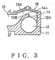
- a branch flow entrance wall 13B which is integrated with the weir 14 in the branch flow passage 13 has a flat surface.
- This branched valve 10 may be connected at the main flow passage 12 to an impurity reducing apparatus, a sterilization apparatus, or a circulation system for super pure water processed by a filter and osmotic membrane apparatus, and at the branch flow passage 13 to the use point of either apparatus or system.
- the sleeve 19 rotates by rotating the handle 16.
- the stem 20 which is engaged with the sleeve 19 by screw threads moves down without rotating, and the diaphragm 15 contacts with the valve seat 14A of the weir 14 with pressure, so that the branch flow is shutted off.
- the branch flow can flow and be controlled in the flux by rotating the handle 16 in the counter-wise direction.
- the branch flow which flows into the branch flow passage 13 from the main flow passage 12 after getting over the weir 14 flows down along the branch flow entrance wall 13B which has the flat surface without being peeled off from the wall 13B, so that a turbulent flow is not generated. Therefore, the pressure loss due to generation of the turbulent flow and the resulting flux loss is prevented. Accordingly, sufficient flux of the branch flow is obtained.
- the basic structure of the the branched valve 10 in this embodiment is the same as that in the first embodiment, except that the branch flow entrance wall 13B has a convex surface.
- the branch flow which flows into the branch flow passage 13 from the main flow passage 12 after getting over the weir 14 flows down along the branch flow entrance wall 13B without peeling off from the wall 13B, and the same effects can be obtained as those in the first embodiment.
- the basic structure of the the branched valve 10 in this embodiment is the same as that in the first embodiment, except that the an outer wall A of the branch flow exit 12A rises vertically from an outer wall B of the main flow passage 12, a side wall C of the weir 14 is located approximately on the center line D of the main flow passage 12, and the branch flow passage 13 is provided so that the center line E thereof is located upper than the center line D of the main flow passage 12.
- the outer wall A of the branch flow exit 12A rises vertically from the outer wall B of the main flow passage 12, so that the outer wall A of the main flow passage 12 does not project outerward largely from the center of the branched valve 10 (handle center) and the width W of the branched valve 10 becomes small.
- the side wall C of the weir 14 is located approximately on the center line D of the main flow passage 12 and overhangs the main flow passage 12 in more degrees.
- the outer wall A of the branch flow exit 12A rises vertically from the outer wall B of the main flow passage 12 and does not overhang the main flow passage 12, so that the prescribed flow area of the branch flow does not decrease, and sufficient flux of the branch flow can be obtained.
- branch flow passage 13 is provided so that the center line E thereof is located upper than the center line D of the main flow passage 12, so that the lower part of the union socket 23 of the branch flow passage 13 does not project downward from the main body 11 of the branched valve 10 and the height L of the branched valve 10 becomes small.
- the main body of the branched valve may consist of corrosion resisting metal such as stainless steel or ceramics, instead of synthetic resin mentioned in the embodiments.
- the system for shutting off the branch flow may be any other shutting off mechanism known publicly such as a stop valve or a gate valve with design modification of the valve disc and the valve seat of the weir, instead of the diaphragm described in the embodiments.
- the union sockets to be connected to the main and branch flow passages may be either the screw-type, flange-type or taper-sleeve type.
- the invention may be applied for an automatic operating valve provided with an actuator for automatic operation, instead of the manual operating valve described in the embodiments.
Landscapes
- Engineering & Computer Science (AREA)
- General Engineering & Computer Science (AREA)
- Mechanical Engineering (AREA)
- Valve Housings (AREA)
- Exhaust-Gas Circulating Devices (AREA)
- Electrically Driven Valve-Operating Means (AREA)
- Valve Device For Special Equipments (AREA)
- Multiple-Way Valves (AREA)
- Lift Valve (AREA)
- Pipe Accessories (AREA)
Priority Applications (5)
| Application Number | Priority Date | Filing Date | Title |
|---|---|---|---|
| US08/001,729 US5327937A (en) | 1993-01-06 | 1993-01-06 | Branched valve |
| ES93100151T ES2132141T3 (es) | 1993-01-06 | 1993-01-07 | Valvula bifurcada. |
| AT93100151T ATE181589T1 (de) | 1993-01-06 | 1993-01-07 | Verzweigtes ventil |
| DE69325440T DE69325440T2 (de) | 1993-01-06 | 1993-01-07 | Verzweigtes Ventil |
| EP19930100151 EP0609469B1 (de) | 1993-01-06 | 1993-01-07 | Verzweigtes Ventil |
Applications Claiming Priority (2)
| Application Number | Priority Date | Filing Date | Title |
|---|---|---|---|
| US08/001,729 US5327937A (en) | 1993-01-06 | 1993-01-06 | Branched valve |
| EP19930100151 EP0609469B1 (de) | 1993-01-06 | 1993-01-07 | Verzweigtes Ventil |
Publications (2)
| Publication Number | Publication Date |
|---|---|
| EP0609469A1 true EP0609469A1 (de) | 1994-08-10 |
| EP0609469B1 EP0609469B1 (de) | 1999-06-23 |
Family
ID=26133040
Family Applications (1)
| Application Number | Title | Priority Date | Filing Date |
|---|---|---|---|
| EP19930100151 Expired - Lifetime EP0609469B1 (de) | 1993-01-06 | 1993-01-07 | Verzweigtes Ventil |
Country Status (5)
| Country | Link |
|---|---|
| US (1) | US5327937A (de) |
| EP (1) | EP0609469B1 (de) |
| AT (1) | ATE181589T1 (de) |
| DE (1) | DE69325440T2 (de) |
| ES (1) | ES2132141T3 (de) |
Cited By (2)
| Publication number | Priority date | Publication date | Assignee | Title |
|---|---|---|---|---|
| EP1610044A3 (de) * | 2004-06-25 | 2006-05-24 | Ratti Giampietro e C. S.n.c. | Absperrventil für Flüssigkeit |
| CN102454809A (zh) * | 2010-10-29 | 2012-05-16 | 上海艾维科阀门有限公司 | 一种隔膜阀 |
Families Citing this family (6)
| Publication number | Priority date | Publication date | Assignee | Title |
|---|---|---|---|---|
| ES2178915B1 (es) * | 2000-03-07 | 2004-04-16 | Plasticos Mondragon, S.A. | Valvula hidraulica de membrana perfeccionada, para regulacion del caudal de fluidos. |
| US6789781B2 (en) | 2001-03-16 | 2004-09-14 | Entegris, Inc. | Reinforced diaphragm valve |
| US6923198B2 (en) * | 2002-03-18 | 2005-08-02 | Entegris, Inc. | Fully drainable weir valve |
| EP1613882A2 (de) * | 2003-04-14 | 2006-01-11 | Swagelok Company | Membranventilsitz |
| US8243864B2 (en) * | 2004-11-19 | 2012-08-14 | Qualcomm, Incorporated | Noise reduction filtering in a wireless communication system |
| DE102013101497B4 (de) * | 2013-02-14 | 2025-11-06 | Bürkert Werke GmbH & Co. KG | Membranventilgehäuse und Verfahren zum Herstellen eines Membranventilgehäuses |
Citations (2)
| Publication number | Priority date | Publication date | Assignee | Title |
|---|---|---|---|---|
| WO1991000460A1 (en) * | 1989-06-28 | 1991-01-10 | Fluoroware, Inc. | Weir valve sampling/injection port |
| WO1992000476A1 (en) * | 1990-06-25 | 1992-01-09 | Saunders Valve Company Limited | Valve for controlling connection to branch passage |
Family Cites Families (5)
| Publication number | Priority date | Publication date | Assignee | Title |
|---|---|---|---|---|
| US2695156A (en) * | 1951-02-24 | 1954-11-23 | Boles B Ivanek | Valve for controlling the flow of milk and the like |
| US2989282A (en) * | 1958-05-19 | 1961-06-20 | Baldwin Lima Hamilton Corp | Irrigation valve |
| DE3507412C1 (de) * | 1985-03-02 | 1986-06-19 | Jakob Dr. 8000 München Hoiß | Membranventil zur Probenentnahme |
| JPH07113424B2 (ja) * | 1985-09-19 | 1995-12-06 | 積水化学工業株式会社 | 分岐バルブ |
| DK247989D0 (da) * | 1989-05-22 | 1989-05-22 | Novo Nordisk As | Membranventil |
-
1993
- 1993-01-06 US US08/001,729 patent/US5327937A/en not_active Expired - Lifetime
- 1993-01-07 ES ES93100151T patent/ES2132141T3/es not_active Expired - Lifetime
- 1993-01-07 AT AT93100151T patent/ATE181589T1/de not_active IP Right Cessation
- 1993-01-07 EP EP19930100151 patent/EP0609469B1/de not_active Expired - Lifetime
- 1993-01-07 DE DE69325440T patent/DE69325440T2/de not_active Expired - Fee Related
Patent Citations (2)
| Publication number | Priority date | Publication date | Assignee | Title |
|---|---|---|---|---|
| WO1991000460A1 (en) * | 1989-06-28 | 1991-01-10 | Fluoroware, Inc. | Weir valve sampling/injection port |
| WO1992000476A1 (en) * | 1990-06-25 | 1992-01-09 | Saunders Valve Company Limited | Valve for controlling connection to branch passage |
Cited By (2)
| Publication number | Priority date | Publication date | Assignee | Title |
|---|---|---|---|---|
| EP1610044A3 (de) * | 2004-06-25 | 2006-05-24 | Ratti Giampietro e C. S.n.c. | Absperrventil für Flüssigkeit |
| CN102454809A (zh) * | 2010-10-29 | 2012-05-16 | 上海艾维科阀门有限公司 | 一种隔膜阀 |
Also Published As
| Publication number | Publication date |
|---|---|
| ATE181589T1 (de) | 1999-07-15 |
| ES2132141T3 (es) | 1999-08-16 |
| US5327937A (en) | 1994-07-12 |
| EP0609469B1 (de) | 1999-06-23 |
| DE69325440T2 (de) | 2000-01-20 |
| DE69325440D1 (de) | 1999-07-29 |
Similar Documents
| Publication | Publication Date | Title |
|---|---|---|
| US5327937A (en) | Branched valve | |
| KR100570492B1 (ko) | 유체 제어 장치 | |
| US6257270B1 (en) | Fluid control device | |
| US5279328A (en) | Weir valve with adjustable bypass | |
| EP0116855A2 (de) | Regelventil | |
| US5326078A (en) | Metal diaphragm valve | |
| KR20010080139A (ko) | 유체제어기 | |
| US2989282A (en) | Irrigation valve | |
| DE69103612T2 (de) | Ventil zum steueren der verbindung zu einer abzweigleitung. | |
| GB2170297A (en) | Aseptic valve with unitary valve seat and lip seals | |
| US4343364A (en) | Sprinkler head construction | |
| JPS56134672A (en) | Ball valve | |
| EP0579678B1 (de) | Ablaufventil | |
| EP0029368A1 (de) | Verfahren zum Einsetzen oder Entfernen eines Hahnkükens | |
| JPH07113424B2 (ja) | 分岐バルブ | |
| JPH09144110A (ja) | 衛生洗浄装置 | |
| US5110088A (en) | Water-control stopper | |
| EP0905454A3 (de) | Anschlussarmatur zum Anschliessen eines Druckausdehnungs-Gefässes an ein Leitungssystem | |
| CN223617491U (zh) | 一种挡水罩结构及研磨设备 | |
| JPH08270825A (ja) | 制御弁 | |
| JP2968092B2 (ja) | 分岐バルブ | |
| SU1254125A2 (ru) | Головка вентильна | |
| JPH07139650A (ja) | 分岐バルブ | |
| EP0515322A1 (de) | Durchflusseinsteller für Hydromassageeinrichtungen | |
| JP2000110949A (ja) | 不凍水抜栓 |
Legal Events
| Date | Code | Title | Description |
|---|---|---|---|
| PUAI | Public reference made under article 153(3) epc to a published international application that has entered the european phase |
Free format text: ORIGINAL CODE: 0009012 |
|
| AK | Designated contracting states |
Kind code of ref document: A1 Designated state(s): AT CH DE ES FR GB IT LI NL SE |
|
| 17P | Request for examination filed |
Effective date: 19940914 |
|
| 17Q | First examination report despatched |
Effective date: 19951016 |
|
| GRAG | Despatch of communication of intention to grant |
Free format text: ORIGINAL CODE: EPIDOS AGRA |
|
| GRAG | Despatch of communication of intention to grant |
Free format text: ORIGINAL CODE: EPIDOS AGRA |
|
| GRAH | Despatch of communication of intention to grant a patent |
Free format text: ORIGINAL CODE: EPIDOS IGRA |
|
| GRAH | Despatch of communication of intention to grant a patent |
Free format text: ORIGINAL CODE: EPIDOS IGRA |
|
| GRAA | (expected) grant |
Free format text: ORIGINAL CODE: 0009210 |
|
| AK | Designated contracting states |
Kind code of ref document: B1 Designated state(s): AT CH DE ES FR GB IT LI NL SE |
|
| RAP1 | Party data changed (applicant data changed or rights of an application transferred) |
Owner name: SEKISUI KAGAKU KOGYO KABUSHIKI KAISHA |
|
| REF | Corresponds to: |
Ref document number: 181589 Country of ref document: AT Date of ref document: 19990715 Kind code of ref document: T |
|
| REG | Reference to a national code |
Ref country code: CH Ref legal event code: EP |
|
| REF | Corresponds to: |
Ref document number: 69325440 Country of ref document: DE Date of ref document: 19990729 |
|
| REG | Reference to a national code |
Ref country code: ES Ref legal event code: FG2A Ref document number: 2132141 Country of ref document: ES Kind code of ref document: T3 |
|
| ITF | It: translation for a ep patent filed | ||
| ET | Fr: translation filed | ||
| REG | Reference to a national code |
Ref country code: CH Ref legal event code: NV Representative=s name: E. BLUM & CO. PATENTANWAELTE |
|
| PLBE | No opposition filed within time limit |
Free format text: ORIGINAL CODE: 0009261 |
|
| STAA | Information on the status of an ep patent application or granted ep patent |
Free format text: STATUS: NO OPPOSITION FILED WITHIN TIME LIMIT |
|
| 26N | No opposition filed | ||
| REG | Reference to a national code |
Ref country code: GB Ref legal event code: IF02 |
|
| PGFP | Annual fee paid to national office [announced via postgrant information from national office to epo] |
Ref country code: SE Payment date: 20040107 Year of fee payment: 12 |
|
| PGFP | Annual fee paid to national office [announced via postgrant information from national office to epo] |
Ref country code: FR Payment date: 20040108 Year of fee payment: 12 |
|
| PGFP | Annual fee paid to national office [announced via postgrant information from national office to epo] |
Ref country code: ES Payment date: 20040123 Year of fee payment: 12 |
|
| PGFP | Annual fee paid to national office [announced via postgrant information from national office to epo] |
Ref country code: DE Payment date: 20041231 Year of fee payment: 13 |
|
| PGFP | Annual fee paid to national office [announced via postgrant information from national office to epo] |
Ref country code: NL Payment date: 20050103 Year of fee payment: 13 |
|
| PGFP | Annual fee paid to national office [announced via postgrant information from national office to epo] |
Ref country code: GB Payment date: 20050105 Year of fee payment: 13 |
|
| PG25 | Lapsed in a contracting state [announced via postgrant information from national office to epo] |
Ref country code: SE Free format text: LAPSE BECAUSE OF NON-PAYMENT OF DUE FEES Effective date: 20050108 Ref country code: ES Free format text: LAPSE BECAUSE OF NON-PAYMENT OF DUE FEES Effective date: 20050108 |
|
| PGFP | Annual fee paid to national office [announced via postgrant information from national office to epo] |
Ref country code: AT Payment date: 20050112 Year of fee payment: 13 |
|
| PGFP | Annual fee paid to national office [announced via postgrant information from national office to epo] |
Ref country code: CH Payment date: 20050117 Year of fee payment: 13 |
|
| EUG | Se: european patent has lapsed | ||
| PG25 | Lapsed in a contracting state [announced via postgrant information from national office to epo] |
Ref country code: FR Free format text: LAPSE BECAUSE OF NON-PAYMENT OF DUE FEES Effective date: 20050930 |
|
| REG | Reference to a national code |
Ref country code: FR Ref legal event code: ST |
|
| PG25 | Lapsed in a contracting state [announced via postgrant information from national office to epo] |
Ref country code: GB Free format text: LAPSE BECAUSE OF NON-PAYMENT OF DUE FEES Effective date: 20060107 Ref country code: AT Free format text: LAPSE BECAUSE OF NON-PAYMENT OF DUE FEES Effective date: 20060107 |
|
| PG25 | Lapsed in a contracting state [announced via postgrant information from national office to epo] |
Ref country code: LI Free format text: LAPSE BECAUSE OF NON-PAYMENT OF DUE FEES Effective date: 20060131 Ref country code: CH Free format text: LAPSE BECAUSE OF NON-PAYMENT OF DUE FEES Effective date: 20060131 |
|
| PGFP | Annual fee paid to national office [announced via postgrant information from national office to epo] |
Ref country code: IT Payment date: 20060131 Year of fee payment: 14 |
|
| REG | Reference to a national code |
Ref country code: ES Ref legal event code: FD2A Effective date: 20050108 |
|
| PG25 | Lapsed in a contracting state [announced via postgrant information from national office to epo] |
Ref country code: NL Free format text: LAPSE BECAUSE OF NON-PAYMENT OF DUE FEES Effective date: 20060801 Ref country code: DE Free format text: LAPSE BECAUSE OF NON-PAYMENT OF DUE FEES Effective date: 20060801 |
|
| REG | Reference to a national code |
Ref country code: CH Ref legal event code: PL |
|
| GBPC | Gb: european patent ceased through non-payment of renewal fee |
Effective date: 20060107 |
|
| NLV4 | Nl: lapsed or anulled due to non-payment of the annual fee |
Effective date: 20060801 |
|
| PG25 | Lapsed in a contracting state [announced via postgrant information from national office to epo] |
Ref country code: IT Free format text: LAPSE BECAUSE OF NON-PAYMENT OF DUE FEES Effective date: 20070107 |