EP0609537A2 - Empilage de panneaux de coffrage à cadre - Google Patents
Empilage de panneaux de coffrage à cadre Download PDFInfo
- Publication number
- EP0609537A2 EP0609537A2 EP93120382A EP93120382A EP0609537A2 EP 0609537 A2 EP0609537 A2 EP 0609537A2 EP 93120382 A EP93120382 A EP 93120382A EP 93120382 A EP93120382 A EP 93120382A EP 0609537 A2 EP0609537 A2 EP 0609537A2
- Authority
- EP
- European Patent Office
- Prior art keywords
- frame
- stack
- frame formwork
- shoe
- elements
- Prior art date
- Legal status (The legal status is an assumption and is not a legal conclusion. Google has not performed a legal analysis and makes no representation as to the accuracy of the status listed.)
- Granted
Links
Images



Classifications
-
- E—FIXED CONSTRUCTIONS
- E04—BUILDING
- E04G—SCAFFOLDING; FORMS; SHUTTERING; BUILDING IMPLEMENTS OR AIDS, OR THEIR USE; HANDLING BUILDING MATERIALS ON THE SITE; REPAIRING, BREAKING-UP OR OTHER WORK ON EXISTING BUILDINGS
- E04G19/00—Auxiliary treatment of forms, e.g. dismantling; Cleaning devices
- E04G19/003—Arrangements for stabilising the forms or for moving the forms from one place to another
-
- B—PERFORMING OPERATIONS; TRANSPORTING
- B65—CONVEYING; PACKING; STORING; HANDLING THIN OR FILAMENTARY MATERIAL
- B65D—CONTAINERS FOR STORAGE OR TRANSPORT OF ARTICLES OR MATERIALS, e.g. BAGS, BARRELS, BOTTLES, BOXES, CANS, CARTONS, CRATES, DRUMS, JARS, TANKS, HOPPERS, FORWARDING CONTAINERS; ACCESSORIES, CLOSURES, OR FITTINGS THEREFOR; PACKAGING ELEMENTS; PACKAGES
- B65D21/00—Nestable, stackable or joinable containers; Containers of variable capacity
- B65D21/02—Containers specially shaped, or provided with fittings or attachments, to facilitate nesting, stacking, or joining together
- B65D21/0209—Containers specially shaped, or provided with fittings or attachments, to facilitate nesting, stacking, or joining together stackable or joined together one-upon-the-other in the upright or upside-down position
- B65D21/0224—Auxiliary removable stacking elements other than covers
Definitions
- the invention relates to a stack of frame formwork elements with mutual fixation, the frame formwork element consisting of a rectangular formwork panel, a circumferential frame consisting of profiles and parallel to the frame sides, cross struts connected to the frame on both end faces, the frame formwork elements horizontal and are arranged one above the other and the frames of the outer frame formwork elements of each stack are arranged on the outside.
- Frame formwork elements are used in the production of formwork for concrete or reinforced concrete buildings and consist of a surrounding frame with cross struts serving for stabilization and one made of wood or other materials such as plastic or the like. assembled formwork panel.
- the frames serve to join the elements together and achieve the stability required for pouring liquid concrete.
- the frame formwork elements are successively removed, generally coated with a preserving, oil-containing substance for reasons of preservation of value, and stacked horizontally one above the other to form a stack, the frames of the outer elements being arranged on the outside.
- the stacks are lifted by a crane, one on the loading area Trucks set down, possibly brought to a construction yard, moved with forklifts and stacked on top of each other.
- the treatment of the surface favors the relative displaceability of the elements of the stack, which are only fixed by gravity, so that, due to the small coefficient of friction, only small transverse forces cause the frame formwork element to fall down.
- the treatment of the surface favors the relative displaceability of the elements of the stack, which are only fixed by gravity, so that, due to the small coefficient of friction, only small transverse forces cause the frame formwork element to fall down.
- a relative displacement of the individual elements relative to one another is also easily possible during a transport on trucks during acceleration and braking processes. Also when transporting and lifting with the help of a forklift there is a risk of falling down unintentionally due to a braking process or an impact individual elements or even the entire stack of resulting forces.
- Another problem is that the size of the individual elements is sometimes different and that stacks of different sizes are often transported on a single vehicle. In this case, additional precautions, such as connecting the frame formwork elements to the vehicle by means of ropes, must be taken, so that the relative displaceability of the individual, stacked stacks is eliminated.
- a device for fixing a stack consisting of several superimposed frame formwork elements is known.
- a vertically oriented angle iron is arranged at each of the four corners of the stack and is connected to the stack by a mandrel arranged on its lower end face, which engages in a corresponding hole in the lowermost frame formwork element. Eyelets located on the upper face of the angle iron are used for connection to a crane.
- a disadvantage is that a special hole is to be made in the bottom frame formwork element.
- a secure fixation is only guaranteed if the stack consists exclusively of elements of the same size and is in the raised state.
- the securing arranged on the inside of the frame and consisting of a pin running transversely to the mandrel and fixing the mandrel in the axial, ie horizontal, direction is relatively difficult and can hardly cope with larger loads.
- the invention is based on the problem of designing devices for improving the safety when transporting frame formwork elements in stacks.
- a stacking shoe is arranged between the adjacent frame formwork elements, that a fork consisting of two legs is provided on two opposite end faces of the stacking shoe a "U" -shaped cross-section is arranged, that the bases of the forks face each other, that the distance between the legs of the forks corresponds to the profile thickness of the frame or the profile strength of the cross struts of a frame formwork element, that the length of the legs is less than the profile height of a frame formwork element is that the downward-pointing legs of a fork enclose the frame or a cross strut of a (lower) frame formwork element.
- the main idea of the invention is to arrange a stacking shoe constructed from two "U" -shaped forks between two adjacent frame formwork elements.
- the forks are on opposite End faces of the stacking shoe positioned and have mutually facing bases.
- the frame or a cross strut of a frame formwork element is located between each of its legs; their distance corresponds to the respective profile thickness, so that the stacking shoe can be plugged onto the frame or the cross strut without play.
- the length of its four legs is shorter than the profile height of a frame formwork element, so that the frame of the elements is supported on the bases of the fork and not the plates on the leg.
- the frame or a cross strut of another frame formwork element is located between the legs of the opposite fork of the stacking shoe. So that it can be easily attached, the frame of the frame formwork element arranged under the stacking shoe is oriented upwards in a manner known per se, and that of the upper one is oriented downward. Gravity fixes the upper frame formwork element in the vertical direction in the stacking shoe, the legs prevent displacement in the horizontal direction perpendicular to the axis of the frame profile they enclose.
- the stacking shoe In addition to fixing stacks of the same size, the stacking shoe also enables stacking of differently sized frame formwork elements, the stack shoes and frame formwork element stack being expediently arranged in such a way that there are two common edges and a common corner. With one if possible The large distance between the shoes arranged on the same long side increases the stability of the stack placed thereon.
- the stacking shoes are not arranged on the frame, but on one of the cross struts, since the spacing of the cross struts is standardized even in the case of panels of different sizes in the same circuit system, so that in the case of a formwork wall, the possibility of connecting elements of different sizes is also provided appropriate brackets exist. Therefore, a stable connection of stacks of different sizes is possible by positioning stack shoes on the cross struts.
- the advantage of the invention is, in particular, that two frame formwork elements or stacks made of them are connected so that they cannot move and slip in both horizontal directions, and that their transport and storage take place with a greatly reduced risk of accidents.
- the mechanical design of the stacking shoe is arbitrary.
- it is proposed to give it an "H" -shaped cross section, that is to say to arrange the bases of the forks at a short distance from one another.
- the advantage is that the stacking shoe is relatively stable and can be made from relatively inexpensive, light wood.
- a stiffener connecting the legs arranged on the same side of the frame or the cross strut of the frame formwork element is also suitable. It can also serve as a handle when attaching and removing the stacking shoe. In the normal case, the stacking shoe is obviously provided with two stiffeners in order to stabilize it both on the inside and on the outside of the frame formwork element.
- the number of stacking shoes used is at least three. For example, two of these are attached to one long side of the frame formwork element, while the third is arranged on one end side is.
- the recommended number of stacking shoes is at least four.
- the stacking shoes are expediently arranged on the long sides or near the corners of the frame formwork elements, the axes of at least two shoes being perpendicular to one another, so that immovability in both horizontal directions and non-tilting of the upper stack is ensured. As a result, the stacking shoes fix two frame formwork elements or a stack consisting of them.
- the height of a cross strut of the stacking shoe in the vertical direction is greater than the height of a fork of a forklift, so that the fork can be inserted under the stack and the stacks can be lifted and transported with a forklift .
- the intermediate space further allows the attachment of a transport sling described later for a crane and stack holders or tensioners to the stack.
- the stacking shoe can also be attached between two cross struts on the frame of the frame formwork element, it is necessary that its axial length is less than the distance between two cross struts of the frame formwork element. This length allows the stack holder to be inserted in a variety of positions, including on the long sides near the corner of the frame.
- the stacking shoe can be attached to the frame or the cross struts more easily and more quickly by bevelled ends, the bevel being arranged on the inside; the axis of the stacking shoe corresponds to the axis of the frame profile enclosed by the legs. Tilting of the stacking shoe and the elements is excluded, and the centering of the frame formwork element to be placed on top of one another is facilitated when stacking on top of one another. A helix angle of approximately 45 ° is preferred.
- Plastic and / or steel and / or aluminum and / or glued wood is recommended as the material for the stacking shoe, since these materials are inexpensive, easy to process, wear-resistant and sufficiently stable.
- a telescopic rod has claws at the ends, that a claw engages around the frame of the bottom and a claw surrounds the frame of the top frame formwork element of the stack, that the telescopic rod at a defined distance the claws can be locked, that the defined distance corresponds to an integral multiple of the thickness of a frame formwork element, and that the telescopic rod is locked.
- a telescopic rod is proposed as a stack holder, provided with claws on the outside and encompassing the frame of a frame formwork element on the outside, composed of two coaxial and displaceable elements.
- the telescopic rod is at different stack heights, i.e. can be used in stacks with a different number of frame formwork elements, since it can be locked in a spacing of the claws corresponding to an integral multiple of the thickness of a frame formwork element. It is also independent of size, i.e. Width and length of the frame formwork elements can be used.
- the telescopic rod is attached in such a way that its length is adapted to the height of the stack and the claws are placed on the frame from the outside.
- the locking causes the two elements of the telescopic rod to move relative to one another, the two claws also moving closer to one another, and thus causing the stack to be braced in the direction of the axis of the telescopic rod.
- the claws encompass the frame profiles, a relative adjustability of the claws is required.
- this bracing is realized by a wedge that can be inserted into the telescopic rod.
- the two elements of the telescopic rod are provided with through openings which are introduced at a spacing of the claws which allows a tolerance of the thickness of the frame formwork elements.
- Another possibility for bracing is to use a known, conventional turnbuckle.
- a stack of frame formwork elements can be fixed in itself in that a stack tensioner has claws at the end, that a claw encompasses the frame of the bottom and a claw surrounds the frame of the top frame formwork element of the stack, that the claws are connected to one another by a belt and that the length of the belt can be varied by a belt tensioner, for example a ratchet or a lever turnbuckle, and is set such that the distance between the claws is an integer Corresponds to multiples of the thickness of a frame formwork element.
- the basic idea is to connect the claws already known from the teaching of claim 10 by means of a belt of variable length.
- a belt tensioner which can be, for example, a ratchet or a lever turnbuckle.
- the result is that the stack is tensioned in itself by the belt.
- the claws are usually arranged one above the other.
- the advantage over telescopic rods is primarily that the mass of the stacking clamp is lower and that its production costs are reduced.
- the belt tensioner can be positioned on a claw.
- the claw equipped with the belt tensioner is arranged above the other, it can be seen as an advantage that the operating personnel is easier to tighten the belt, since it grips the protruding end, can be pulled down by the body weight and can thus fix the stack in itself.
- At least two telescopic rods and / or stack clamps are located opposite each other on the middle of a long side or end face a plate stack attached and locked.
- the use of a stack holder on one side of the stack of panels is recommended, since in this case the securing in all four horizontal directions is not only by pressing together, but also by touching and positioning the middle frame formwork elements by the stack holder itself he follows.
- Optimal protection is obtained if - which in the most general case is not absolutely necessary - only plates of the same size are available within a stack.
- the locking devices must be released, the stack holders removed and the frame formwork elements individually removable from the stack.
- the material of the spacer proves to be expedient in the special rubber, since due to its elasticity it can be used on frames of different sizes within certain tolerances. Furthermore, the recess can be designed such that the spacer sits sufficiently firmly on the claw and can only be lost with difficulty.
- the shoe has a leg which engages from below in the inside of the corner of the bottom frame formwork element of the stack.
- the main idea of this invention is to use a shoe that grips the corner of the bottom element of a stack from below.
- the shoe is usually on the outside on both the corner of the meeting frame profiles, so that it is fixed in both horizontal directions, while the fastening is carried out in the vertical direction by the gravitational force pressing the frame formwork elements onto the shoe.
- Such a design of the shoe prevents incorrect operation, since it can only be fixed at corners of the frame formwork elements.
- Flexible traction elements arranged in the vertical direction are attached to the shoe. These traction elements are connected to a crane at their other end and enable the stack to be lifted and transported by a crane.
- the flexible tension element is attached to the shoe and is connected to the crane's hanger on its opposite end by means of a ring or triangular eyelet, for example.
- the flexible tension element can be endless, ie closed in itself. One end it is hung relatively quickly and easily into the hook of the crane and is displaceable relative to the shoe, so that it automatically positions itself in such a way that the strands running on both sides of the hook are equally loaded. It therefore also automatically adapts to frame formwork elements of different sizes.
- the lifespan of the flexible tension element can be decisively extended by a casing surrounding it.
- a shoe is inserted from below at each corner of the lowermost frame switching element.
- tension elements there are therefore four tension elements, whereby by using endless tension elements the individual frame formwork elements can be fixed in both horizontal directions, the stack is therefore optimally secured if a section of the tension element rests on each longitudinal and end face of the frame formwork element.
- Stacking shoes attached under the lower frame formwork element make it easier to attach the transport sling because they provide the space required for insertion below the stack.
- the stack can now be lifted, pivoted and lowered by the crane due to the frame switching elements fixed in all spatial directions without endangering the people in the vicinity.
- this is an easily attachable and detachable spring which engages in the profile recesses of the frame.
- a rubber buffer arranged on the inside of the corner of the frame is proposed as the locking device. It fixes the shoe in both horizontal directions and can be used on differently dimensioned frame profiles due to its elasticity.
- the rubber buffer is, for example, a cylinder or a truncated cone.
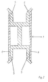
- the stacking shoe (1) shown in FIG. 1 has an "H" -shaped cross section; the distance between the two legs corresponds to the profile thickness of the frame (3) of a frame formwork element (2).
- This design enables two frame formwork elements (2) to be fixed against one another, or, what is preferred, two stacks of frame formwork elements (2).
- the lower stack is stacked in such a way that the plate (4) of the uppermost, outer frame formwork element lies downwards and its frame (3) lies outwards, ie upwards. After stacking up a stack, there are at least three To increase the stability, however, preferably four stacking shoes (1) are placed on the frame (3) of the uppermost frame formwork element (2).
- the bevelled inner edges make it easier to put on the stacking shoe and put the top stack on and avoid jamming as they provide guidance.
- the upper stack not shown in the drawing, would be placed on the stacking shoes (1) with the frame (3) of the lowermost frame formwork element (2) facing downwards. If frame formwork elements (2) of different sizes are to be stacked, it is sometimes advisable not to arrange the stacking shoes (1) on the frame (3) but on the cross struts of the frame formwork elements (2).
- the individual stacks are composed of frame formwork elements (2) of the same size and layered on top of one another with at least one common corner, the most appropriate type of layering depending on the concrete dimensions of the frame formwork elements (2).
- the height of the cross strut of the stacking shoe (1) is greater than the height of a forklift fork, so that the individual stacks can be loaded with a forklift and also an easy attachment of the transport hangers according to the invention to the corners of the bottom frame formwork element (2) of a stack.
- FIG. 2 The alternative embodiment of a stacking shoe (1) shown in Figure 2 consists of two "U" -shaped forks, the bases (i.e. base areas) of which are connected by a web running parallel to the legs (5) of the forks and are arranged at a distance from one another.
- the end faces of the legs (5) are beveled outwards.
- a stiffener (6) is arranged on each side of the web and connects the legs (5) arranged on one side.
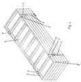
- the stack of frame formwork elements shown in FIG. 3 is fixed by stack holders.
- the latter is constructed from a telescopic rod (7) (which can be locked in a multiple of the thickness of a frame formwork element (2), the distance between the claws (8) can be locked) and the frame (3) of the frame formwork elements (2) on the rear embracing claw (8).
- the locking device is released and is then locked, in one embodiment of the invention the claws (8) and thus the frame formwork elements (2) are braced at the same time.
- the frame formwork elements (2) are fixed by stack clamps.
- the latter like the stack holder shown in FIG. 3 - consist of claws (8) encompassing the frames (3) of the frame formwork elements (2), but in contrast are connected to one another by a belt (9).
- a belt tensioner (10) arranged on the respective upper claw (8) serves to vary the distance between the claws and to tension the stack.
- FIG. 5 shows the use of transport hangers when transporting stacked formwork elements (2) by means of a crane.
- a shoe (11) which is pushed into the frame corner of a frame formwork element (2) from below and which has the shape of a "U" in a side view is locked on it.
- the shoe (11) is shaped so that it encompasses both frame profiles joined together at the corner.
- a shoe (11) is attached to each corner of the stack of frame formwork elements (2) of the same size for connection to the crane suspension (14) and with a flexible tension element (12) in turn connected to the hook (13) connected to the crane suspension (14). All tension elements (12) are of the same length, so that an exact horizontal orientation of the frame formwork elements (2) is guaranteed when pivoting with the crane.
- the tension elements (12) are endless, that is to say they are self-contained and can be displaced relative to the shoes (11). Since there is a flexible tension element (12) on each longitudinal or end face of the frame formwork elements (2), there is no horizontal displacement of the frame formwork elements (2) with each other during transport by crane, ie with tensioned tension elements (12) and therefore no more falling possible.
Landscapes
- Engineering & Computer Science (AREA)
- Architecture (AREA)
- Mechanical Engineering (AREA)
- Civil Engineering (AREA)
- Structural Engineering (AREA)
- Forms Removed On Construction Sites Or Auxiliary Members Thereof (AREA)
- Moulds, Cores, Or Mandrels (AREA)
- Manufacturing Of Tubular Articles Or Embedded Moulded Articles (AREA)
- Machines For Manufacturing Corrugated Board In Mechanical Paper-Making Processes (AREA)
- Buffer Packaging (AREA)
Applications Claiming Priority (2)
| Application Number | Priority Date | Filing Date | Title |
|---|---|---|---|
| DE4302604 | 1993-01-30 | ||
| DE4302604A DE4302604B4 (de) | 1993-01-30 | 1993-01-30 | Stapel aus Rahmenschalungselementen |
Publications (3)
| Publication Number | Publication Date |
|---|---|
| EP0609537A2 true EP0609537A2 (fr) | 1994-08-10 |
| EP0609537A3 EP0609537A3 (fr) | 1994-11-23 |
| EP0609537B1 EP0609537B1 (fr) | 1998-09-30 |
Family
ID=6479266
Family Applications (1)
| Application Number | Title | Priority Date | Filing Date |
|---|---|---|---|
| EP93120382A Expired - Lifetime EP0609537B1 (fr) | 1993-01-30 | 1993-12-17 | Empilage de panneaux de coffrage à cadre |
Country Status (3)
| Country | Link |
|---|---|
| EP (1) | EP0609537B1 (fr) |
| AT (1) | ATE171752T1 (fr) |
| DE (2) | DE4302604B4 (fr) |
Cited By (1)
| Publication number | Priority date | Publication date | Assignee | Title |
|---|---|---|---|---|
| CN118083762A (zh) * | 2024-04-29 | 2024-05-28 | 河北易昌光伏发电有限责任公司 | 一种太阳能光伏板安装用吊运装置 |
Families Citing this family (3)
| Publication number | Priority date | Publication date | Assignee | Title |
|---|---|---|---|---|
| DE9419472U1 (de) * | 1994-12-05 | 1995-02-16 | Effkemann, Manfred, 48683 Ahaus | Stapelvorrichtung für Schalungsplatten |
| DE20307269U1 (de) | 2003-05-09 | 2003-07-24 | Doka Industrie Gmbh, Amstetten | Sicherungselement |
| CN115676588B (zh) * | 2022-11-08 | 2023-05-12 | 中交二航局结构工程有限公司 | 一种钢梁自动安装设备及工艺 |
Family Cites Families (20)
| Publication number | Priority date | Publication date | Assignee | Title |
|---|---|---|---|---|
| GB416269A (en) * | 1934-02-26 | 1934-09-13 | Gypsum Lime And Alabastine Can | Improvements in or relating to the packing of wallboard and the like and clips therefor |
| US2676835A (en) * | 1951-11-28 | 1954-04-27 | Eldon O Mckinney | Adjustable carrier |
| DE966770C (de) * | 1955-02-06 | 1957-09-05 | Erwin Schulze | Flaschentransportkasten |
| FR1328941A (fr) * | 1962-03-21 | 1963-06-07 | Sud Aviation | Perfectionnement apporté aux équipements de levage et d'arrimage de charges |
| DE1170864B (de) * | 1962-06-06 | 1964-05-21 | Mannesmann Ag | Foerder- und Stapelvorrichtung fuer Rohre |
| US3350129A (en) * | 1965-05-12 | 1967-10-31 | United States Steel Corp | Plate handling device |
| DE2546144C2 (de) * | 1975-10-15 | 1984-07-12 | Fa. August Thiele, 5860 Iserlohn | Anschlaggeschirr für Rinnenschüsse |
| DE7736356U1 (de) * | 1977-11-28 | 1978-04-20 | Siegel Geb Gmbh Co Kg | Kunststoff-Formstueck zur Abstuetzung aufeinandergestapelter gleicher Drahtkoerbe |
| DE2803484A1 (de) * | 1978-01-27 | 1979-08-02 | Wanzl Metallwarenfabrik Kg | Fuss zum stellen oder uebereinanderstapeln von aus metalldraehten gebildeten teilen |
| DE2943274C2 (de) * | 1979-10-26 | 1982-03-25 | Josef 7611 Steinach Maier | Stapelsicherung, bestehend aus wenigstens einer an einer vertikalen Stapelkante anliegenden Winkelschiene |
| SU920169A1 (ru) * | 1980-07-02 | 1982-04-15 | Государственный Проектный И Научно-Исследовательский Институт "Челябинский Промстройниипроект" | Несъемна опалубка дл монолитных железобетонных конструкций |
| DE8427004U1 (de) * | 1984-09-13 | 1984-12-06 | Fleck, Dorothea, 2070 Großhansdorf | Klemmvorrichtung |
| NL8500681A (nl) * | 1985-03-11 | 1986-10-01 | Empee Golfkarton B V | Strapbeugel. |
| DE3608479A1 (de) * | 1986-03-14 | 1987-09-17 | Wolfgang Baumann | Vorrichtung, insbesondere fuer das bauwesen, zum gestapelten transportieren und/oder lagern von ebenen gegenstaenden |
| US4736975A (en) * | 1986-12-31 | 1988-04-12 | Nabisco Brands, Inc. | Method and apparatus for loading and unloading palletized loads |
| DE3705521C1 (en) * | 1987-02-20 | 1988-03-24 | Ver Glaswerke Gmbh | Arrangement for securing vertically stacked products against falling over |
| DE3735876A1 (de) * | 1987-10-23 | 1989-05-03 | Karl Netzer | Klemmvorrichtung zum loesbaren verbinden von uebereinander und/oder nebeneinander zu lagernden faessern |
| DE8909441U1 (de) * | 1989-08-04 | 1989-10-05 | Siemens AG, 1000 Berlin und 8000 München | Sicherungselement für kistenförmige Stapeleinheiten |
| FR2668129A1 (fr) * | 1990-10-17 | 1992-04-24 | Noulet Jose | Un dispositif pour assembler des conteneurs. |
| DE9114168U1 (de) * | 1991-11-14 | 1992-01-16 | Overath, Udo, 5204 Lohmar | Abstandhalter für Glasscheiben |
-
1993
- 1993-01-30 DE DE4302604A patent/DE4302604B4/de not_active Expired - Lifetime
- 1993-12-17 DE DE59309024T patent/DE59309024D1/de not_active Expired - Lifetime
- 1993-12-17 EP EP93120382A patent/EP0609537B1/fr not_active Expired - Lifetime
- 1993-12-17 AT AT93120382T patent/ATE171752T1/de active
Cited By (1)
| Publication number | Priority date | Publication date | Assignee | Title |
|---|---|---|---|---|
| CN118083762A (zh) * | 2024-04-29 | 2024-05-28 | 河北易昌光伏发电有限责任公司 | 一种太阳能光伏板安装用吊运装置 |
Also Published As
| Publication number | Publication date |
|---|---|
| EP0609537A3 (fr) | 1994-11-23 |
| EP0609537B1 (fr) | 1998-09-30 |
| DE59309024D1 (de) | 1998-11-05 |
| DE4302604A1 (de) | 1994-08-04 |
| DE4302604B4 (de) | 2004-12-30 |
| ATE171752T1 (de) | 1998-10-15 |
Similar Documents
| Publication | Publication Date | Title |
|---|---|---|
| EP3581537B1 (fr) | Monte-charge | |
| EP2590867B1 (fr) | Dispositif de transport | |
| DE4427073B4 (de) | Stapel aus Rahmenschalungselementen | |
| DE4302604B4 (de) | Stapel aus Rahmenschalungselementen | |
| DE202017000424U1 (de) | Stellrahmenpalette | |
| DE2127862A1 (de) | Transportables Laborgehause | |
| EP0641685B1 (fr) | Dispositif pour assurer la sécurité du transport de récipients | |
| EP3524535B1 (fr) | Châssis de palette pour être posé sur une palette de transport | |
| DE19517925C1 (de) | Gestell zum Lagern und/oder Transportieren von Glasscheibenpaketen | |
| DE202008001157U1 (de) | Transportanordnung | |
| DE19931248A1 (de) | Palette zur Aufnahme einer Last, insbesondere eines Zweirads | |
| DE202017103919U1 (de) | Transportpalette und Transportanordnung | |
| DE3515202A1 (de) | Rollvorrichtung, insbesondere fuer paletten, transport- und stapelbehaelter | |
| DE9401032U1 (de) | Tragevorrichtung für Ladepaletten | |
| DE29820497U1 (de) | Pritschenfahrzeug mit Aufbau zur Erweiterung der Ladekapazität | |
| DE19905669A1 (de) | Vielfach verwendbares Lager- und Transportmittel mit umweltfreundlichen Verpackungen | |
| EP0086741A1 (fr) | Caisse-palette à parois en forme de grille | |
| DE102024136687A1 (de) | Transportbehälter und Betriebsverfahren dafür | |
| DE102024131280A1 (de) | Transportbehälter für Gerüstbauteile | |
| DE2531730C3 (de) | Vorrichtung zum Transport von rinnenförmigen Profilabschnitten für den untertägigen Streckenausbau | |
| DE9419468U1 (de) | Bauzaun-Palette | |
| EP3165478A1 (fr) | Dispositif de stockage modulaire pour un objet en forme de plaque | |
| DE202023105119U1 (de) | Langpalette für Langgut | |
| DE3430461A1 (de) | Buendelgeschirr fuer den transport von hoelzern des untertagebetriebs, insbesondere schwellenartige hoelzer | |
| DE8429202U1 (de) | Stapelbares Lager- und Transportgestell fuer profilglasbahnen |
Legal Events
| Date | Code | Title | Description |
|---|---|---|---|
| PUAI | Public reference made under article 153(3) epc to a published international application that has entered the european phase |
Free format text: ORIGINAL CODE: 0009012 |
|
| AK | Designated contracting states |
Kind code of ref document: A2 Designated state(s): AT BE CH DE DK FR GB IT LI NL |
|
| PUAL | Search report despatched |
Free format text: ORIGINAL CODE: 0009013 |
|
| AK | Designated contracting states |
Kind code of ref document: A3 Designated state(s): AT BE CH DE DK FR GB IT LI NL |
|
| 17P | Request for examination filed |
Effective date: 19941103 |
|
| 17Q | First examination report despatched |
Effective date: 19950915 |
|
| GRAG | Despatch of communication of intention to grant |
Free format text: ORIGINAL CODE: EPIDOS AGRA |
|
| GRAG | Despatch of communication of intention to grant |
Free format text: ORIGINAL CODE: EPIDOS AGRA |
|
| GRAH | Despatch of communication of intention to grant a patent |
Free format text: ORIGINAL CODE: EPIDOS IGRA |
|
| GRAH | Despatch of communication of intention to grant a patent |
Free format text: ORIGINAL CODE: EPIDOS IGRA |
|
| GRAA | (expected) grant |
Free format text: ORIGINAL CODE: 0009210 |
|
| AK | Designated contracting states |
Kind code of ref document: B1 Designated state(s): AT BE CH DE DK FR GB IT LI NL |
|
| PG25 | Lapsed in a contracting state [announced via postgrant information from national office to epo] |
Ref country code: NL Free format text: LAPSE BECAUSE OF FAILURE TO SUBMIT A TRANSLATION OF THE DESCRIPTION OR TO PAY THE FEE WITHIN THE PRESCRIBED TIME-LIMIT Effective date: 19980930 Ref country code: IT Free format text: LAPSE BECAUSE OF FAILURE TO SUBMIT A TRANSLATION OF THE DESCRIPTION OR TO PAY THE FEE WITHIN THE PRE;WARNING: LAPSES OF ITALIAN PATENTS WITH EFFECTIVE DATE BEFORE 2007 MAY HAVE OCCURRED AT ANY TIME BEFORE 2007. THE CORRECT EFFECTIVE DATE MAY BE DIFFERENT FROM THE ONE RECORDED.SCRIBED TIME-LIMIT Effective date: 19980930 Ref country code: GB Free format text: LAPSE BECAUSE OF FAILURE TO SUBMIT A TRANSLATION OF THE DESCRIPTION OR TO PAY THE FEE WITHIN THE PRESCRIBED TIME-LIMIT Effective date: 19980930 Ref country code: FR Free format text: LAPSE BECAUSE OF FAILURE TO SUBMIT A TRANSLATION OF THE DESCRIPTION OR TO PAY THE FEE WITHIN THE PRESCRIBED TIME-LIMIT Effective date: 19980930 |
|
| REF | Corresponds to: |
Ref document number: 171752 Country of ref document: AT Date of ref document: 19981015 Kind code of ref document: T |
|
| REG | Reference to a national code |
Ref country code: CH Ref legal event code: EP |
|
| REF | Corresponds to: |
Ref document number: 59309024 Country of ref document: DE Date of ref document: 19981105 |
|
| PG25 | Lapsed in a contracting state [announced via postgrant information from national office to epo] |
Ref country code: LI Free format text: LAPSE BECAUSE OF NON-PAYMENT OF DUE FEES Effective date: 19981231 Ref country code: DK Free format text: LAPSE BECAUSE OF FAILURE TO SUBMIT A TRANSLATION OF THE DESCRIPTION OR TO PAY THE FEE WITHIN THE PRESCRIBED TIME-LIMIT Effective date: 19981231 Ref country code: CH Free format text: LAPSE BECAUSE OF NON-PAYMENT OF DUE FEES Effective date: 19981231 Ref country code: BE Free format text: LAPSE BECAUSE OF NON-PAYMENT OF DUE FEES Effective date: 19981231 |
|
| EN | Fr: translation not filed | ||
| NLV1 | Nl: lapsed or annulled due to failure to fulfill the requirements of art. 29p and 29m of the patents act | ||
| GBV | Gb: ep patent (uk) treated as always having been void in accordance with gb section 77(7)/1977 [no translation filed] |
Effective date: 19980930 |
|
| BERE | Be: lapsed |
Owner name: SIEGLER JOHANNES Effective date: 19981231 Owner name: SIEGLER WALTER Effective date: 19981231 |
|
| PLBE | No opposition filed within time limit |
Free format text: ORIGINAL CODE: 0009261 |
|
| STAA | Information on the status of an ep patent application or granted ep patent |
Free format text: STATUS: NO OPPOSITION FILED WITHIN TIME LIMIT |
|
| REG | Reference to a national code |
Ref country code: CH Ref legal event code: PL |
|
| 26N | No opposition filed | ||
| PGFP | Annual fee paid to national office [announced via postgrant information from national office to epo] |
Ref country code: DE Payment date: 20121204 Year of fee payment: 20 |
|
| PGFP | Annual fee paid to national office [announced via postgrant information from national office to epo] |
Ref country code: AT Payment date: 20121214 Year of fee payment: 20 |
|
| REG | Reference to a national code |
Ref country code: DE Ref legal event code: R071 Ref document number: 59309024 Country of ref document: DE |
|
| REG | Reference to a national code |
Ref country code: DE Ref legal event code: R071 Ref document number: 59309024 Country of ref document: DE |
|
| PG25 | Lapsed in a contracting state [announced via postgrant information from national office to epo] |
Ref country code: DE Free format text: LAPSE BECAUSE OF EXPIRATION OF PROTECTION Effective date: 20131218 |
|
| REG | Reference to a national code |
Ref country code: AT Ref legal event code: MK07 Ref document number: 171752 Country of ref document: AT Kind code of ref document: T Effective date: 20131217 |