EP0609558B1 - Sonnenblende für Fahrzeuge - Google Patents
Sonnenblende für Fahrzeuge Download PDFInfo
- Publication number
- EP0609558B1 EP0609558B1 EP93120883A EP93120883A EP0609558B1 EP 0609558 B1 EP0609558 B1 EP 0609558B1 EP 93120883 A EP93120883 A EP 93120883A EP 93120883 A EP93120883 A EP 93120883A EP 0609558 B1 EP0609558 B1 EP 0609558B1
- Authority
- EP
- European Patent Office
- Prior art keywords
- sun visor
- mirror
- frame
- visor body
- depression
- Prior art date
- Legal status (The legal status is an assumption and is not a legal conclusion. Google has not performed a legal analysis and makes no representation as to the accuracy of the status listed.)
- Expired - Lifetime
Links
- 239000000463 material Substances 0.000 claims description 20
- 238000010438 heat treatment Methods 0.000 claims description 7
- 238000006073 displacement reaction Methods 0.000 claims description 6
- 239000004743 Polypropylene Substances 0.000 claims description 5
- -1 polypropylene Polymers 0.000 claims description 5
- 229920001155 polypropylene Polymers 0.000 claims description 5
- 239000002245 particle Substances 0.000 claims description 4
- 239000006260 foam Substances 0.000 claims description 3
- 230000004927 fusion Effects 0.000 claims description 2
- 230000006835 compression Effects 0.000 claims 1
- 238000007906 compression Methods 0.000 claims 1
- 238000004519 manufacturing process Methods 0.000 description 3
- 238000003466 welding Methods 0.000 description 3
- 238000002347 injection Methods 0.000 description 2
- 239000007924 injection Substances 0.000 description 2
- 238000002844 melting Methods 0.000 description 2
- 230000008018 melting Effects 0.000 description 2
- 230000006378 damage Effects 0.000 description 1
- 238000003825 pressing Methods 0.000 description 1
- 238000004064 recycling Methods 0.000 description 1
Images
Classifications
-
- B—PERFORMING OPERATIONS; TRANSPORTING
- B60—VEHICLES IN GENERAL
- B60J—WINDOWS, WINDSCREENS, NON-FIXED ROOFS, DOORS, OR SIMILAR DEVICES FOR VEHICLES; REMOVABLE EXTERNAL PROTECTIVE COVERINGS SPECIALLY ADAPTED FOR VEHICLES
- B60J3/00—Antiglare equipment associated with windows or windscreens; Sun visors for vehicles
- B60J3/02—Antiglare equipment associated with windows or windscreens; Sun visors for vehicles adjustable in position
- B60J3/0204—Sun visors
- B60J3/0278—Sun visors structure of the body
-
- B—PERFORMING OPERATIONS; TRANSPORTING
- B60—VEHICLES IN GENERAL
- B60J—WINDOWS, WINDSCREENS, NON-FIXED ROOFS, DOORS, OR SIMILAR DEVICES FOR VEHICLES; REMOVABLE EXTERNAL PROTECTIVE COVERINGS SPECIALLY ADAPTED FOR VEHICLES
- B60J3/00—Antiglare equipment associated with windows or windscreens; Sun visors for vehicles
- B60J3/02—Antiglare equipment associated with windows or windscreens; Sun visors for vehicles adjustable in position
- B60J3/0204—Sun visors
- B60J3/0278—Sun visors structure of the body
- B60J3/0282—Sun visors structure of the body specially adapted for a courtesy mirror
Definitions
- the invention relates to a sun visor for vehicles with a sun visor body which consists of polypropylene particle foam and which has a recess on a broad side, into which a mirror held by a frame formed as an injection molded part made of polypropylene is inserted.
- a sun visor has become known from EP-A-0 503 150.
- the invention is based on the object of designing a sun visor of the type mentioned in such a way that complex fastening manipulations as well as additional insert elements in the sun visor body can be dispensed with.
- rational and therefore cost-effective production and emphasis is placed on simplifying recycling.
- the frame is integrally connected to the sun visor body, the integral connection of the frame equipped with the mirror being effected through its partial displacement of material generated by material heating and softening up to melting.
- the frame has a circumferential flange, which is supported on the sun visor body, and a circumferential, approximately perpendicular to the flange, plunging into the recess with partially arranged web extensions, which are pressed into the bottom of the recess after prior heating and with are fused to the material of the sun visor body.
- a sun visor body is foamed in a conventional manner and a mirror frame is injection molded in a conventional manner.
- a covering material After covering the sun visor body with a covering material, it is only necessary to press the mirror frame equipped with a mirror into the recess provided for this purpose in the sun visor body.
- the partial web extensions z. B. heating by means of a welding mirror.
- the web has a circumferential step-like offset at its free end region, against which the mirror is supported, and that the mirror is displaced from the free web edge to the rear mirror edge on the frame by partial displacement of material by heat and pressure is set.
- the material displacement can e.g. B. can be accomplished quickly and easily by means of a heated mandrel and leads to a reliable fixing of the mirror on the mirror frame.
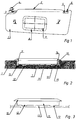
- the sun visor comprises a sun visor body 1, in the upper longitudinal edge area 2 of which a sun visor axis 3 is embedded on the drawing left side.
- the sun visor axis 3 is mounted at the other end in a bearing block 4 which can be fastened to the vehicle body.
- the sun visor body 1 On the right side of the drawing, the sun visor body 1 has a counter bearing pin 6 which crosses a recess 5 and which can be detachably latched into a counter bearing block (not shown).
- the sun visor body 1 is formed from polypropylene particle foam and has a recess 7 on a broad side, into which a mirror 9 carried by a frame 8 is inserted.
- the frame 8 consists of a molded part made of polypropylene material and is therefore, like the sun visor body, fully recyclable.
- the frame 8 has a circumferential flange 10, which is supported on the sun visor body 1, and a circumferential, approximately perpendicular to the flange 10, plunging into the recess 7 with partially arranged web extensions 12.
- the web extensions 12 are shown in the sectional view according to FIG. 2 and even more clearly in the side view of the frame 8 according to FIG. 3.
- connection of the frame 8 and the mirror 9 to the sun visor body 1 is preferably carried out in that a welding mirror 13, indicated by dash-dotted lines in FIG. 3, is applied to the web extension 12 in order to heat and melt the web extensions 12.
- a welding mirror 13 indicated by dash-dotted lines in FIG. 3
- the frame 8 is pressed into the recess 7 of the sun visor body 1, which causes the sun visor body and frame material to fuse together.
- the particles of the sun visor body 1 are shown compressed in the connection area.
- the web 11 of the frame 8 has at its free end region a circumferential step-shaped shoulder 14 against which the mirror 9 is supported.
- the mirror 9 is fixed to the rear mirror edge on the frame 8 by partial material displacement of the free web edge generated by heat and pressure supply, which can also have web extensions for this purpose.
- the setpoints are marked with 15.
Landscapes
- Engineering & Computer Science (AREA)
- Mechanical Engineering (AREA)
- Rear-View Mirror Devices That Are Mounted On The Exterior Of The Vehicle (AREA)
- Lining Or Joining Of Plastics Or The Like (AREA)
- Injection Moulding Of Plastics Or The Like (AREA)
- Laminated Bodies (AREA)
Description
- Die Erfindung bezieht sich auf eine Sonnenblende für Fahrzeuge mit einem Sonnenblendenkörper, der aus Polypropylen-Partikelschaum besteht und der an einer Breitseite eine Vertiefung aufweist, in die ein von einem als aus Polypropylen bestehendes Spritzgußteil ausgebildeten Rahmen gehaltener Spiegel eingesetzt ist. Eine derartige Sonnenblende ist durch die EP-A- 0 503 150 bekanntgeworden.
- Es ist allgemein bekannt, an den Sonnenblendenkörpern von Sonnenblenden Spiegel anzuordnen. Zur Befestigung des Spiegels am Sonnenblendenkörper werden verschiedene Systeme eingesetzt. So werden die Spiegelrahmen häufig mit einer den Sonnenblendenkörper umgebenden Umhüllung verschweißt, was aufwendig ist. Bei anderen herkömmlichen Befestigungssystemen weist der Sonnenblendenkörper örtlich eingeschäumte Einlagen mit Anbindungen zum Verkrallen, Verschrauben oder Verklipsen von am Spiegelrahmen angeordneten Halterungselementen auf. Der Nachteil hierbei ist in der aufwendigen Fertigung zu sehen.
- Der Erfindung liegt hiernach die Aufgabe zugrunde, eine Sonnenblende der eingangs genannten Art so zu gestalten, daß auf aufwendige Befestigungsmanipulationen wie auch auf zusätzliche Einlageelemente im Sonnenblendenkörper verzichtet werden kann. Ferner wird eine rationelle und damit kostengünstige Fertigung sowie Wert auf eine Vereinfachung des Recyclings gelegt.
- Zur Lösung dieser Aufgabe ist erfindungsgemäß vorgesehen, daß der Rahmen stoffschlüssig mit dem Sonnenblendenkörper verbunden ist, wobei die stoffschlüssige Verbindung des mit Spiegel bestückten Rahmens durch dessen partielle durch Materialerwärmung und Erweichung erzeugte Materialverdrängung bis hin zum Anschmelzen erfolgt ist.
- Bevorzugterweise ist dabei vorgesehen, daß der Rahmen einen umlaufenden, sich auf da Sonnenblendenkörper abstützenden Flansch und einen umlaufenden, etwa senkrecht zum Flansch ausgerichteten, in die Vertiefung eintauchenden Steg mit partiell angeordneten Stegverlängerungen aufweist, welche nach vorheriger Erwärmung in den Boden der Vertiefung eingepreßt und mit dem Material des Sonnenblendenkörpers verschmolzen sind.
- Bei der Herstellung der erfindungsgemäßen Sonnenblende wird demnach ein Sonnenblendenkörper in herkömmlicher Weise geschäumt und ein Spiegelrahmen in herkömmlicher Weise gespritzt. Nach dem etwaigen Beziehen des Sonnenblendenkörpers mit einem Umhüllungsmaterial braucht lediglich noch der mit Spiegel bestückte Spiegelrahmen in die hierfür im Sonnenblendenkörper vorgesehene Vertiefung eingedrückt zu werden. Vor dem Eindrücken des Spiegelrahmens ist es jedoch zwecks Herstellung eher stoffschlüssigen Verbindung mit dem Material des Sonnenblendenkörpers erforderlich, eine partielle Materialerwärmung und Erweichung bis hin zum Anschmelzen herbeizuführen. Zweckmäßigerweise wird man dabei die partiellen Stegverlängerungen z. B. mittels eines Schweißspiegels entsprechend weit Erwärmen. Durch das Eindrücken des Spiegelrahmens dringen die Stegverlängerungen in das Material des Sonnenblendenkörpers ein, wobei es zur Verschmelzung und Herstellung einer unlösbaren Verbindung kommt. Wie Versuche gezeigt haben, läßt sich die so hergestellte stoffschlüssige Verbindung nur durch Materialzerstörung wieder lösen.
- In Ausgestaltung der Erfindung kann noch vorgesehen sein, daß der Steg an seinem freien Endbereich eine umlaufende stufenförmige Absetzung aufweist, gegen die der Spiegel abgestützt ist und daß der Spiegel durch partielle durch Wärme- und Druckzufuhr erzeugte Materialverdrängung des freien Stegrandes zum rückseitigen Spiegelrand hin am Rahmen festgelegt ist. Die Materialverdrängung kann z. B. mittels eines erwärmten Dorns schnell und problemlos bewerkstelligt werden und führt zu einer zuverlässigen Festlegung des Spiegels am Spiegelrahmen.
- Ein Ausführungsbeispiel der Erfindung wird nachfolgend anhand der Zeichnung näher erläutert. Es zeigen:
- Fig. 1 eine Sonnenblende in ihrer Gebrauchsstellung,
- Fig. 2 einen Schnitt II - II nach Fig. 1 und
- Fig. 3 eine Einzelheit der Sonnenblende.
- Die Sonnenblende umfaßt einen Sonnenblendenkörper 1, in dessen oberen Längskantenbereich 2 zeichnungslinksseitig eine Sonnenblendenachse 3 eingelagert ist. Die Sonnenblendenachse 3 ist anderendig in einem an der Fahrzeugkarosserie befestigbaren Lagerböckchen 4 gelagert. Zeichnungsrechtsseitig weist der Sonnenblendenkörper 1 einen, eine Ausnehmung 5 querenden Gegenlagerzapfen 6 auf, der lösbar in ein nicht gezeigtes Gegenlagerböckchen einrastbar ist.
- Der Sonnenblendenkörper 1 ist aus Polypropylen-Partikelschaum gebildet und weist auf einer Breitseite eine Vertiefung 7 auf, in die ein von einem Rahmen 8 getragener Spiegel 9 eingesetzt ist. Der Rahmen 8 besteht aus einem aus Polypropylenmaterial gebildeten Spritzling und ist daher, ebenso wie der Sonnenblendenkörper, voll recyclebar.
- Der Rahmen 8 weist einen umlaufenden, sich auf dem Sonnenblendenkörper 1 abstützenden Flansch 10 und einen umlaufenden, etwa senkrecht zum Flansch 10 ausgerichteten, in die Vertiefung 7 eintauchenden Steg 11 mit partiell angeordneten Stegverlängerungen 12 auf. Die Stegverlängerungen 12 sind in der Schnittdarstellung nach Fig. 2 und noch deutlicher in der Seitenansicht des Rahmens 8 nach Fig. 3 gezeigt.
- Die Verbindung des Rahmens 8 und Spiegel 9 mit dem Sonnenblendenkörper 1 erfolgt bevorzugt dadurch, daß an die Stegverlängerung 12 ein, in Fig. 3 strichpunktiert angedeuteter Schweißspiegel 13 angelegt wird, um die Stegverlängerungen 12 zu erwärmen und anzuschmelzen. Unmittelbar nach Wegnahme des Schweißspiegels 13 wird der Rahmen 8 in die Vertiefung 7 des Sonnenblendenkörpers 1 eingedrückt, wobei es zum Zusammenschmelzen von Sonnenblendenkörper- und Rahmen-Material kommt. Im Verbindungsbereich sind die Partikel des Sonnenblendenkörpers 1 verdichtet dargestellt.
- Der Steg 11 des Rahmens 8 weist an seinem freien Endbereich eine umlaufende stufenförmige Absetzung 14 auf, gegen die der Spiegel 9 abgestützt ist. Dabei ist der Spiegel 9 durch partielle durch Wärme und Druckzufuhr erzeugte Materialverdrängung des freien Stegrandes, der auch hierfür Stegverlängerungen aufweisen kann, zum rückseitigen Spiegelrand hin am Rahmen 8 festgelegt. Die Festlegungspunkte sind mit 15 kenntlich gemacht.
Claims (3)
- Sonnenblende für Fahrzeuge mit einem Sonnenblendenkörper (1), der aus Polypropylen-Partikelschaum besteht und der in einer Breitseite eine Vertiefung (7) aufweist, in die ein von einem als aus Polypropylen bestehendes Spritzgußteil ausgebildeten Rahmen (8) gehaltener Spiegel (9) eingesetzt ist, dadurch gekennzeichnet, daß der Rahmen (8) stoffschlüssig mit dem Sonnenblendenkörper (1) verbunden ist, wobei die stoffschlüssige Verbindung des mit Spiegel (9) bestückten Rahmens (8) durch dessen partielle durch Materialerwärmung und Erweichung erzeugte Materialverdrängung bis hin zum Anschmelzen erfolgt ist.
- Sonnenblende nach Anspruch 1, dadurch gekennzeichnet, daß der Rahmen (8) einen umlaufenden, sich auf dem Sonnenblendenkörper (1) abstützenden Flansch (10) und einen umlaufenden, etwa senkrecht zum Flansch (10) ausgerichteten, in die Vertiefung (7) eintauchenden Steg (11) mit partiell angeordneten Stegverlängerungen (12) aufweist, welche nach vorheriger Erwärmung in den öden der Vertiefung (7) eingepreßt und mit dem Material des Sonnenblendenkörpers (1) verschmolzen sind.
- Sonnenblende nach Anspruch 1 oder 2, dadurch gekennzeichnet, daß der Steg (11) an seinem freien Endbereich eine umlaufende stufenförmige Absetzung (14) aufweist, gegen die der Spiegel (9) abgestützt ist und daß der Spiegel (9) durch partielle durch Wärme- und Druckzufuhr erzeugte Materialverdrängung des freien Stegrandes zum rückseitigen Spiegelrand hin am Rahmen (8) festgelegt ist.
Applications Claiming Priority (2)
| Application Number | Priority Date | Filing Date | Title |
|---|---|---|---|
| DE4302607 | 1993-01-30 | ||
| DE4302607A DE4302607C2 (de) | 1993-01-30 | 1993-01-30 | Sonnenblende für Fahrzeuge |
Publications (3)
| Publication Number | Publication Date |
|---|---|
| EP0609558A1 EP0609558A1 (de) | 1994-08-10 |
| EP0609558B1 true EP0609558B1 (de) | 1996-09-11 |
| EP0609558B2 EP0609558B2 (de) | 2001-10-04 |
Family
ID=6479268
Family Applications (1)
| Application Number | Title | Priority Date | Filing Date |
|---|---|---|---|
| EP93120883A Expired - Lifetime EP0609558B2 (de) | 1993-01-30 | 1993-12-24 | Sonnenblende für Fahrzeuge |
Country Status (5)
| Country | Link |
|---|---|
| US (1) | US5429407A (de) |
| EP (1) | EP0609558B2 (de) |
| JP (1) | JPH0829668B2 (de) |
| DE (2) | DE4302607C2 (de) |
| ES (1) | ES2094453T3 (de) |
Cited By (1)
| Publication number | Priority date | Publication date | Assignee | Title |
|---|---|---|---|---|
| EP0985568A2 (de) | 1998-09-12 | 2000-03-15 | Volkswagen Aktiengesellschaft | Sonnenblende für Fahrzeuge |
Families Citing this family (9)
| Publication number | Priority date | Publication date | Assignee | Title |
|---|---|---|---|---|
| US5643053A (en) * | 1993-12-27 | 1997-07-01 | Applied Materials, Inc. | Chemical mechanical polishing apparatus with improved polishing control |
| US5603547A (en) * | 1994-02-03 | 1997-02-18 | Finn; Joseph R. | Pivot rod with protective molding sleeve |
| DE19541391A1 (de) | 1995-11-07 | 1997-05-15 | Happich Gmbh Gebr | Spiegelbaueinheit |
| US5716092A (en) * | 1996-06-11 | 1998-02-10 | Prince Corporation | Visor and method of manufacturing |
| US6012757A (en) * | 1998-07-24 | 2000-01-11 | Becker Group Europe Gmbh | Sun visor for vehicles |
| US6698815B1 (en) | 2002-10-02 | 2004-03-02 | Grupo Antolin Ingenieria, S.A. | Sun visor with mirror assembly |
| US20050006923A1 (en) * | 2003-07-08 | 2005-01-13 | Johnson Controls Technology Company | Visor for a vehicle |
| US20060261627A1 (en) * | 2005-04-01 | 2006-11-23 | Johnson Controls Technology Company | Visor and method for making a visor |
| FR2980776B1 (fr) | 2011-10-03 | 2014-08-22 | Airbus Operations Sas | Nacelle d'aeronef comportant un panneau pour le traitement acoustique integrant des canaux d'air chaud et au moins un canal annulaire |
Family Cites Families (30)
| Publication number | Priority date | Publication date | Assignee | Title |
|---|---|---|---|---|
| DE1068571B (de) * | 1959-11-05 | Gebr. Happich G.m.b.H., Wuppertal· Ellberfel'd. Er1L: Karl Brandes, Wuppertal-Elberfeld, und Hans-Ulrich Heibeck, Remscheid-Luttringhausen | Sonnenblende, insbesondere fur Kraftfahrzeuge | |
| NL6400609A (de) † | 1963-02-16 | 1964-08-17 | ||
| DE2102917A1 (en) * | 1971-01-22 | 1972-08-03 | Lang, Heinrich, 8501 Stadeln | Motorcar sun visor - made of polyurethane foam with integral rear view mirror |
| GB1327985A (en) * | 1971-01-28 | 1973-08-22 | Ford Motor Co | Motor vehicle sun visor |
| DE7423932U (de) * | 1974-07-13 | 1974-10-17 | Gebr Happich Gmbh | Sonnenblende insbesondere fuer die verwendung in fahrzeugen |
| DE7614171U1 (de) * | 1976-05-05 | 1976-09-09 | Gebr. Happich Gmbh, 5600 Wuppertal | Sonnenblende, insbesondere fuer fahrzeuge |
| DE2619844C3 (de) * | 1976-05-05 | 1981-03-26 | Gebr. Happich Gmbh, 42285 Wuppertal | Sonnenblende, insbesondere für Fahrzeuge |
| JPS5347211U (de) * | 1976-09-27 | 1978-04-21 | ||
| IT1070254B (it) * | 1976-10-08 | 1985-03-29 | Iao Industrie Riunite Spa | Visiera parasole con specchietto di cortesia per autoveicoli |
| DE7921916U1 (de) * | 1979-08-01 | 1979-11-08 | Gebr. Happich Gmbh, 5600 Wuppertal | Sonnenblende fuer fahrzeuge mit einem im sonnenblendenkoerper angeordneten spiegel |
| DE3000810A1 (de) * | 1980-01-11 | 1981-07-30 | Gebr. Happich Gmbh, 5600 Wuppertal | Sonnenblende mit beleuchtetem spiegel |
| DE3008175A1 (de) * | 1980-03-04 | 1981-09-17 | Gebr. Happich Gmbh, 5600 Wuppertal | Sonnenblende, insbesondere fuer fahrzeuge |
| DE3011158A1 (de) * | 1980-03-22 | 1981-10-01 | Gebr. Happich Gmbh, 5600 Wuppertal | Sonnenblende, insbesondere fuer fahrzeuge |
| FR2513578A1 (fr) * | 1981-09-28 | 1983-04-01 | Mecanismes Comp Ind De | Pare-soleil, notamment pour vehicule automobile |
| DE8201176U1 (de) * | 1982-01-20 | 1982-06-16 | Zipperle, Wolfgang, 7140 Ludwigsburg | Sonnenblende fuer kraftfahrzeuge |
| DE3375560D1 (en) * | 1982-07-20 | 1988-03-10 | Happich Gmbh Gebr | Sun visor, especially for vehicles |
| US4711483A (en) * | 1986-01-21 | 1987-12-08 | Irvin Industries, Inc. | Motor vehicle visor with removable mirror assembly |
| ES292646Y (es) * | 1986-03-01 | 1987-03-01 | Gabas Cebollero Carlos | Nuevo parasol de estructura perfeccionada para vehiculos automoviles |
| ES292645Y (es) * | 1986-03-01 | 1987-03-01 | Gabas Cebollero Carlos | Parasol de vehiculos automoviles de estructura mejorada |
| SE466956B (sv) * | 1987-10-28 | 1992-05-04 | Autopart Sweden Ab | Solskydd foer motorfordon |
| FR2628797B1 (fr) * | 1988-03-17 | 1990-08-24 | Rockwell Cim | Support pour fixer des objets a des composants de l'habitacle d'automobiles, notamment pour fixer une glace a un pare-soleil en matiere plastique mousse |
| DE3909687A1 (de) * | 1989-03-23 | 1990-09-27 | Zipperle Eugen Gmbh & Co Kg | Sonnenblende fuer kraftfahrzeuge |
| DE4015739A1 (de) † | 1990-05-16 | 1991-11-21 | Hoechst Ag | Verfahren zur herstellung eines verbundkoerpers aus polypropylen |
| DE4023243C1 (de) * | 1990-07-21 | 1991-11-21 | Gebr. Happich Gmbh, 5600 Wuppertal, De | |
| US5209880A (en) * | 1990-07-27 | 1993-05-11 | Neo-Ex Lab. Inc. | Process for making a sun visor by molding a pair of shells and bonding them together |
| DE4107696A1 (de) * | 1991-03-09 | 1992-09-10 | Happich Gmbh Gebr | Sonnenblende fuer fahrzeuge |
| DE9110948U1 (de) * | 1991-09-04 | 1991-10-17 | Eugen Zipperle GmbH & Co KG, 7144 Asperg | Sonnenblende für Kraftfahrzeuge |
| DE4227646B4 (de) † | 1992-08-21 | 2004-11-04 | Utescheny Ag | Sonnenblende für Kraftfahrzeuge und ein Verfahren zur Herstellung |
| US5331518A (en) † | 1992-09-22 | 1994-07-19 | Prince Corporation | Visor mirror cover assembly |
| DE4242939A1 (de) * | 1992-12-18 | 1994-06-23 | Happich Gmbh Gebr | Sonnenblende für Fahrzeuge sowie Verfahren und Vorrichtung zum Herstellen derselben |
-
1993
- 1993-01-30 DE DE4302607A patent/DE4302607C2/de not_active Expired - Fee Related
- 1993-12-22 US US08/172,037 patent/US5429407A/en not_active Expired - Lifetime
- 1993-12-24 DE DE59303754T patent/DE59303754D1/de not_active Expired - Lifetime
- 1993-12-24 EP EP93120883A patent/EP0609558B2/de not_active Expired - Lifetime
- 1993-12-24 ES ES93120883T patent/ES2094453T3/es not_active Expired - Lifetime
-
1994
- 1994-01-25 JP JP6006391A patent/JPH0829668B2/ja not_active Expired - Fee Related
Cited By (2)
| Publication number | Priority date | Publication date | Assignee | Title |
|---|---|---|---|---|
| EP0985568A2 (de) | 1998-09-12 | 2000-03-15 | Volkswagen Aktiengesellschaft | Sonnenblende für Fahrzeuge |
| DE19841848B4 (de) * | 1998-09-12 | 2007-03-01 | Volkswagen Ag | Sonnenblende für Fahrzeuge |
Also Published As
| Publication number | Publication date |
|---|---|
| ES2094453T3 (es) | 1997-01-16 |
| DE4302607A1 (de) | 1994-08-04 |
| JPH0829668B2 (ja) | 1996-03-27 |
| DE4302607C2 (de) | 2002-12-05 |
| JPH06234323A (ja) | 1994-08-23 |
| EP0609558A1 (de) | 1994-08-10 |
| DE59303754D1 (de) | 1996-10-17 |
| US5429407A (en) | 1995-07-04 |
| EP0609558B2 (de) | 2001-10-04 |
Similar Documents
| Publication | Publication Date | Title |
|---|---|---|
| DE69627259T2 (de) | Luftsackabdeckung und Herstellungsverfahren dafür | |
| DE69627578T2 (de) | Airbagabdeckung und Verfahren zu deren Herstellung | |
| DE19819573B4 (de) | Instrumententafel | |
| DE4448050B4 (de) | Verfahren zur Herstellung einer Airbag-Abdeckung | |
| DE10345026B4 (de) | Innenverkleidungsteil zur Abdeckung eines Airbags | |
| EP1084052B1 (de) | Fahrzeugteil mit einer airbagvorrichtung und herstellungsverfahren für ein solches fahrzeugteil | |
| EP0602451A1 (de) | Sonnenblende für Fahrzeuge sowie Verfahren und Vorrichtung zum Herstellen derselben | |
| DE69837605T2 (de) | VERFAHREN ZUM HERSTELLEN EINES EINE HAUT TRAGENDEN, IN EINER FORM EXPANDIERTEN GEFORMTEN KÖRPERS UND DER KöRPER | |
| EP2358568A1 (de) | Gassack | |
| EP0609558B2 (de) | Sonnenblende für Fahrzeuge | |
| DE69105065T3 (de) | Sonnenblende und Verfahren zu deren Herstellung. | |
| DE10334644B4 (de) | Verfahren zur Verarbeitung eines textilen Flächengebildes, textiles Flächengebilde, Bezug und Vorrichtung, insbesondere Fahrzeugsitz | |
| EP0652126B1 (de) | Sonnenblende für Fahrzeuge sowie Verfahren zum Herstellen einer solchen | |
| EP1970183B1 (de) | Nichtsichtbare Airbagklappe, Vorrichtung und Verfahren zu ihrer Herstellung | |
| EP0586971B1 (de) | Sonnenblende für Fahrzeuge | |
| DE3883839T2 (de) | Verfahren zur Herstellung einer Autosonnenblende. | |
| DE102007037800A1 (de) | Hohles Bauelement mit verstärktem Stützelement und Prozess zu dessen Herstellung | |
| DE3439474A1 (de) | Tuer- oder fensterprofil aus kunststoff und werkzeug zum herstellen des profils | |
| EP1134107B1 (de) | Abschirmelement für Kraftfahrzeuge | |
| DE69713182T2 (de) | Verfahren zum Herstellen eines wiederverwertbaren Sitzkissens und Sitz ausgerüsted mit diesem Kissen | |
| DE60101787T2 (de) | Verfahren und vorrichtung zur herstellung von behältern | |
| DE102015007886B4 (de) | Verbundbauteil für ein Fahrzeug, insbesondere einen Kraftwagen | |
| DE9110948U1 (de) | Sonnenblende für Kraftfahrzeuge | |
| DE3833673A1 (de) | Sonnenblende fuer fahrzeuge | |
| DE8201176U1 (de) | Sonnenblende fuer kraftfahrzeuge |
Legal Events
| Date | Code | Title | Description |
|---|---|---|---|
| PUAI | Public reference made under article 153(3) epc to a published international application that has entered the european phase |
Free format text: ORIGINAL CODE: 0009012 |
|
| 17P | Request for examination filed |
Effective date: 19940531 |
|
| AK | Designated contracting states |
Kind code of ref document: A1 Designated state(s): DE ES FR GB IT SE |
|
| 17Q | First examination report despatched |
Effective date: 19951027 |
|
| GRAG | Despatch of communication of intention to grant |
Free format text: ORIGINAL CODE: EPIDOS AGRA |
|
| GRAH | Despatch of communication of intention to grant a patent |
Free format text: ORIGINAL CODE: EPIDOS IGRA |
|
| GRAH | Despatch of communication of intention to grant a patent |
Free format text: ORIGINAL CODE: EPIDOS IGRA |
|
| GRAA | (expected) grant |
Free format text: ORIGINAL CODE: 0009210 |
|
| ITPR | It: changes in ownership of a european patent |
Owner name: C.O N.ME EPO REG. 92;BECKER GROUP EUROPE GMBH |
|
| AK | Designated contracting states |
Kind code of ref document: B1 Designated state(s): DE ES FR GB IT SE |
|
| PG25 | Lapsed in a contracting state [announced via postgrant information from national office to epo] |
Ref country code: GB Free format text: LAPSE BECAUSE OF FAILURE TO SUBMIT A TRANSLATION OF THE DESCRIPTION OR TO PAY THE FEE WITHIN THE PRESCRIBED TIME-LIMIT Effective date: 19960911 |
|
| ET | Fr: translation filed | ||
| REF | Corresponds to: |
Ref document number: 59303754 Country of ref document: DE Date of ref document: 19961017 |
|
| RAP2 | Party data changed (patent owner data changed or rights of a patent transferred) |
Owner name: BECKER GROUP EUROPE GMBH |
|
| ITF | It: translation for a ep patent filed | ||
| GBT | Gb: translation of ep patent filed (gb section 77(6)(a)/1977) |
Effective date: 19961206 |
|
| REG | Reference to a national code |
Ref country code: ES Ref legal event code: FG2A Ref document number: 2094453 Country of ref document: ES Kind code of ref document: T3 |
|
| PLBI | Opposition filed |
Free format text: ORIGINAL CODE: 0009260 |
|
| 26 | Opposition filed |
Opponent name: MAGNA ZIPPEX AUTOTECHNIK GMBH Effective date: 19970319 |
|
| REG | Reference to a national code |
Ref country code: FR Ref legal event code: CD |
|
| PLBQ | Unpublished change to opponent data |
Free format text: ORIGINAL CODE: EPIDOS OPPO |
|
| PLBI | Opposition filed |
Free format text: ORIGINAL CODE: 0009260 |
|
| 26 | Opposition filed |
Opponent name: ROCKWELL LIGHT VEHICLE SYSTEMS INC. Effective date: 19970611 Opponent name: MAGNA ZIPPEX AUTOTECHNIK GMBH Effective date: 19970319 |
|
| PLBF | Reply of patent proprietor to notice(s) of opposition |
Free format text: ORIGINAL CODE: EPIDOS OBSO |
|
| PLBF | Reply of patent proprietor to notice(s) of opposition |
Free format text: ORIGINAL CODE: EPIDOS OBSO |
|
| PLAB | Opposition data, opponent's data or that of the opponent's representative modified |
Free format text: ORIGINAL CODE: 0009299OPPO |
|
| R26 | Opposition filed (corrected) |
Opponent name: MAGNA ZIPPEX AUTOTECHNIK GMBH * 970611 MERITOR LIG Effective date: 19970319 |
|
| RAP2 | Party data changed (patent owner data changed or rights of a patent transferred) |
Owner name: JOHNSON CONTROLS INTERIORS GMBH & CO. KG |
|
| PGFP | Annual fee paid to national office [announced via postgrant information from national office to epo] |
Ref country code: SE Payment date: 20001120 Year of fee payment: 8 Ref country code: GB Payment date: 20001120 Year of fee payment: 8 |
|
| PGFP | Annual fee paid to national office [announced via postgrant information from national office to epo] |
Ref country code: ES Payment date: 20001212 Year of fee payment: 8 |
|
| PLAW | Interlocutory decision in opposition |
Free format text: ORIGINAL CODE: EPIDOS IDOP |
|
| PLAW | Interlocutory decision in opposition |
Free format text: ORIGINAL CODE: EPIDOS IDOP |
|
| PUAH | Patent maintained in amended form |
Free format text: ORIGINAL CODE: 0009272 |
|
| STAA | Information on the status of an ep patent application or granted ep patent |
Free format text: STATUS: PATENT MAINTAINED AS AMENDED |
|
| 27A | Patent maintained in amended form |
Effective date: 20011004 |
|
| AK | Designated contracting states |
Kind code of ref document: B2 Designated state(s): DE ES FR GB IT SE |
|
| PG25 | Lapsed in a contracting state [announced via postgrant information from national office to epo] |
Ref country code: SE Free format text: LAPSE BECAUSE OF NON-PAYMENT OF DUE FEES Effective date: 20011225 |
|
| PG25 | Lapsed in a contracting state [announced via postgrant information from national office to epo] |
Ref country code: ES Free format text: LAPSE BECAUSE OF FAILURE TO SUBMIT A TRANSLATION OF THE DESCRIPTION OR TO PAY THE FEE WITHIN THE PRESCRIBED TIME-LIMIT Effective date: 20020115 |
|
| ET3 | Fr: translation filed ** decision concerning opposition | ||
| GBV | Gb: ep patent (uk) treated as always having been void in accordance with gb section 77(7)/1977 [no translation filed] |
Effective date: 19960911 |
|
| PG25 | Lapsed in a contracting state [announced via postgrant information from national office to epo] |
Ref country code: IT Free format text: LAPSE BECAUSE OF NON-PAYMENT OF DUE FEES;WARNING: LAPSES OF ITALIAN PATENTS WITH EFFECTIVE DATE BEFORE 2007 MAY HAVE OCCURRED AT ANY TIME BEFORE 2007. THE CORRECT EFFECTIVE DATE MAY BE DIFFERENT FROM THE ONE RECORDED. Effective date: 20051224 |
|
| PLAB | Opposition data, opponent's data or that of the opponent's representative modified |
Free format text: ORIGINAL CODE: 0009299OPPO |
|
| PGFP | Annual fee paid to national office [announced via postgrant information from national office to epo] |
Ref country code: FR Payment date: 20130130 Year of fee payment: 20 Ref country code: DE Payment date: 20121231 Year of fee payment: 20 |
|
| REG | Reference to a national code |
Ref country code: DE Ref legal event code: R071 Ref document number: 59303754 Country of ref document: DE |
|
| PG25 | Lapsed in a contracting state [announced via postgrant information from national office to epo] |
Ref country code: DE Free format text: LAPSE BECAUSE OF EXPIRATION OF PROTECTION Effective date: 20131225 |