EP0609573A1 - Combiné d'usinage multifonctions pour travailler le bois et le métal - Google Patents
Combiné d'usinage multifonctions pour travailler le bois et le métal Download PDFInfo
- Publication number
- EP0609573A1 EP0609573A1 EP93200283A EP93200283A EP0609573A1 EP 0609573 A1 EP0609573 A1 EP 0609573A1 EP 93200283 A EP93200283 A EP 93200283A EP 93200283 A EP93200283 A EP 93200283A EP 0609573 A1 EP0609573 A1 EP 0609573A1
- Authority
- EP
- European Patent Office
- Prior art keywords
- wood
- bench
- machine tool
- machine
- tool according
- Prior art date
- Legal status (The legal status is an assumption and is not a legal conclusion. Google has not performed a legal analysis and makes no representation as to the accuracy of the status listed.)
- Granted
Links
Images


Classifications
-
- B—PERFORMING OPERATIONS; TRANSPORTING
- B27—WORKING OR PRESERVING WOOD OR SIMILAR MATERIAL; NAILING OR STAPLING MACHINES IN GENERAL
- B27C—PLANING, DRILLING, MILLING, TURNING OR UNIVERSAL MACHINES FOR WOOD OR SIMILAR MATERIAL
- B27C9/00—Multi-purpose machines; Universal machines; Equipment therefor
- B27C9/04—Multi-purpose machines; Universal machines; Equipment therefor with a plurality of working spindles
-
- B—PERFORMING OPERATIONS; TRANSPORTING
- B23—MACHINE TOOLS; METAL-WORKING NOT OTHERWISE PROVIDED FOR
- B23Q—DETAILS, COMPONENTS, OR ACCESSORIES FOR MACHINE TOOLS, e.g. ARRANGEMENTS FOR COPYING OR CONTROLLING; MACHINE TOOLS IN GENERAL CHARACTERISED BY THE CONSTRUCTION OF PARTICULAR DETAILS OR COMPONENTS; COMBINATIONS OR ASSOCIATIONS OF METAL-WORKING MACHINES, NOT DIRECTED TO A PARTICULAR RESULT
- B23Q37/00—Metal-working machines, or constructional combinations thereof, built-up from units designed so that at least some of the units can form parts of different machines or combinations; Units therefor in so far as the feature of interchangeability is important
- B23Q37/002—Convertible machines, e.g. from horizontally working into vertically working
Definitions
- This invention concerns a multifunctional machine tool, with the characteristic of comprising a large number of supports and work benches, equipped with electric tools and manual equipment.
- the objective of these machines is that of solving problems of work organisation, reducing the need for large working areas and the cost of individual equipment, ergonomically combining the operational mechanical parts in a single multifunctional unit.
- the single-cylinder planer and double-cylinder planer the cropper and bench disk saw, the planer and slotting machine, and the like; amongst those with three functions the combination of single-cylinder planer, double-cylinder planer and slotting machine is known. Also known are those with five functions comprising single-cylinder planer, double cylinder planer, slotting machine, shaper and disk saw, and also those with seven or eight functions which have in addition to the functions just listed also a carriage for squaring up and tenoning and a device for making the disk of the circular saw inclinable.
- Combined machine tools generally comprise an enbloc metal frame, made of structural steel or casting, in which a motor with speed reducer and various tools or equipment are mounted, the latter arranged under the work bench or at the sides of the base, and which can be set up, operatively, in their corresponding work area, as required.
- the first is the poor utilisation of the empty spaces on the inside of the frame and laterally with respect to said frame.
- the second is the poor ergonomics of the tools equipped with guiding carriages which considerably protrude from the opposite sides of the supporting frame, with evident discomfort for the operator and the need for considerable space around the machine itself.
- the object of this invention is to eliminate all the aforementioned difficulties, to overcome the limits met and to definitively create a new device able, thanks to its original combination of elements, to satisfy economical and industrial interests, thus distinctly improving the pre-existing technology.
- a combined multifunctional machine tool characterized in the claims, which provides a supporting structure able to receive and make operative a double series of tools, both manual and electrical, with the relative working parts and service components such as driving, adjustment, transmission, locking, and resetting mechanisms able to ensure all the indispensable and auxiliary processes relative to craftwork of wood, and alternatively all the processes relative to craftwork of metals in general and of iron in particular can be effected with results of a professional standard, providing a combined dual-purpose machine for two distinct technical sectors, giving two machines in one.
- the machine considered here also due to the fact that its structure, which is suitably interacting, also due to the fact that it allows a band saw and a slotting carriage to be connected on the same side of a squaring carriage, achieves the objective of completely exploiting spaces and volumes thus perfecting the relationship between space, cost, ergonomics, and quality of results on the one hand and the limitation of use and interference on the other.
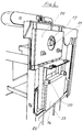
- the machine described comprises a metal frame 1, provided with various work benches 2 and various recessed compartments 3, suitable for containing and supporting the foldable or sliding work benches provided for working wood and metals.
- machine 4 in question has a disk saw 5 for carrying out straight or inclined cuts, a vertical band saw 6 for cutting large thicknesses and small joint work, a horizontal miller 7 for milling and tenoning with the aid of the relevant squaring carriage 15, a polishing belt 8 for finishing work, a single-cylinder planer and a double-cylinder planer 9 for planing work and a head vice 47 with slots and dogs for less specific work.
- the machine for working metal, is equipped with a disk cropper 10 for straight and angled cuts, a pillar drill 11 for drilling, a bench grinder 12 for grinding and sharpening, a bench vice 13 for mechanical working and finishing and an anvil 14 for riveting and heading metals.
- carriage 15 for squaring and tenoning, belt 8 for polishing, and carriage 16 for slotting are visible, for the working of wood.
- the wood lathe 24, positioned under the main work bench which is divided into two foldable half-benches, comprises a lateral support 25 with belt pulleys 26 and ball bearings 27 for the rotation of the workpiece, fixed onto internal horizontal bench 31, a support 28 for the manual tool for turning and a tailstock 29 which is machined on the head of bench grinder 12 fixed to the extractable and rotatable saddle 51.
- the bench grinder in fact, as shown in figure 11, is activated and motorized by means of the said workpiece carrying spindle 30 of wood lathe 24, rotating the vice carrying saddle 51 by 180 degrees, which is slidable with adjustable movement on the internal horizontal plane 31.
- the machine has a band saw 6 to be folded onto work bench 32 from its resting position 33 on the side of the base 1, as shown in figure 10, and a disk saw 5, coming out of the half-bench 32 and adjustable in height by intervening on device 48, which can be inclined by means of controls 49 better illustrated in figure 10.
- This equipment allows both normal and inclined cuts to be carried out thanks to the possibility of inclining said disk, square or variously angled cuts thanks to squaring carriage 15 equipped with column 37 and workpiece locking arm 38, parallel cuts thanks to parallel guide 34 with rod 35 marked in millimetres and block 36 of micrometric adjustment and angulation.
- the machine has a single-cylinder planer 9 with the aid of said parallel guide 34.
- the machine utilizes the shaper 7 aided by guide 45 equipped with pressers and by carriage 15.
- the band saw 6 has specific guides not shown in the drawing.
- the assembly 39 of the equipment for working metals is prevalently arranged on various lateral supports 40, which can be folded on the work bench.
- the machine is equipped with bench vice 13 on rotatable plate 41, a drill 11 with pillar support 42, an anvil 14, a disk cropper 10 having a vice and accessories fixed to work bench 43, a bench vice 12 shown in figure 11.
- the operation of the various tools and equipment for working and finishing is obtained by means of three electric motors positioned on the inside of the base, said motors, either directly or by means of suitable belt transmissions, drive respectively: the shaper and the cutter for iron (the first motor); the band saw (the second motor); a group of equipment that is the lathe, the polishing band, the disk saw, the bench grinder, the slotting machine, and the single and double cylinder planers (the third).
- Some tools furthermore, require different speeds of rotation and these are automatically selected by suitable devices for changing speed, or acting directly on relationships between driving pulleys and driven pulleys also using a rapid device which allows the displacement of the belt in the various grooves of the pulleys, acting on a presser which, by lowering the intermediate horizontal shaft disengages or engages the said belt.
- a system of rapid tooth couplings are utilized, which are not visible in the drawings and are of known type, constituted by two parts, the first comprising a sleeve splined to the shaft with a key which makes it integral to the shaft but free to move longitudinally, the second part is constituted by a toothed element which is free to rotate on the shaft but not to move along it; to the latter a pulley is coupled which transfers its movement to the pulley of the driven shaft of the tool.
- the displacement of the sleeve is obtained by means of a rod the end of which runs in a circular groove of the said sleeve.
- the rod in turn is driven by a three-spoked wheel, which move following a set track 50, which is visible in figure 10, made in the side of the machine.
- spokes the central one, serves to operate the lateral displacements and in fact, running along the horizontal lengths of the slit, it brings the rod in line with the previously chosen sleeve.
- the other two spokes come out from the sump only rotating the central spoke towards the top or towards the bottom in the appropriate vertical slits and control the engaging of the sleeve contemporeanously operating the disengagement of the stop lever and allowing the displacement of said sleeve for coupling which takes place by running along the appropriate horizontal length in the sump.
- the disengagement of the coupling and the engagement of the stop lever are carried out by the reverse manoevre.
- the conversion from the arrangement for working wood to that for working iron, and thus the motorisation of the relevant tools is activated by rotating the half-bench 43 by 180 degrees on its fixed part 32, coupling the tang of the cutter in the shaft of the shaper and rotating the equipment lying in the side from the resting position to position and lock them on the half work bench 43.
- the combined machine described may be classified as an indispensable piece of equipment for craftwork by amateurs and artisans, providing, in a single operative unit, all the tools necessary to allow multiple processes to be carried out on wood and metal.
Landscapes
- Engineering & Computer Science (AREA)
- Mechanical Engineering (AREA)
- Life Sciences & Earth Sciences (AREA)
- Wood Science & Technology (AREA)
- Forests & Forestry (AREA)
- Milling, Drilling, And Turning Of Wood (AREA)
- Chemical And Physical Treatments For Wood And The Like (AREA)
Priority Applications (3)
| Application Number | Priority Date | Filing Date | Title |
|---|---|---|---|
| DE69310890T DE69310890D1 (de) | 1993-02-04 | 1993-02-04 | Kombinierte Werkzeugmaschine für mehrere Bearbeitungsarten von Holz und Metall |
| AT93200283T ATE153271T1 (de) | 1993-02-04 | 1993-02-04 | Kombinierte werkzeugmaschine für mehrere bearbeitungsarten von holz und metall |
| EP93200283A EP0609573B1 (fr) | 1993-02-04 | 1993-02-04 | Combiné d'usinage multifonctions pour travailler le bois et le métal |
Applications Claiming Priority (1)
| Application Number | Priority Date | Filing Date | Title |
|---|---|---|---|
| EP93200283A EP0609573B1 (fr) | 1993-02-04 | 1993-02-04 | Combiné d'usinage multifonctions pour travailler le bois et le métal |
Publications (2)
| Publication Number | Publication Date |
|---|---|
| EP0609573A1 true EP0609573A1 (fr) | 1994-08-10 |
| EP0609573B1 EP0609573B1 (fr) | 1997-05-21 |
Family
ID=8213607
Family Applications (1)
| Application Number | Title | Priority Date | Filing Date |
|---|---|---|---|
| EP93200283A Expired - Lifetime EP0609573B1 (fr) | 1993-02-04 | 1993-02-04 | Combiné d'usinage multifonctions pour travailler le bois et le métal |
Country Status (3)
| Country | Link |
|---|---|
| EP (1) | EP0609573B1 (fr) |
| AT (1) | ATE153271T1 (fr) |
| DE (1) | DE69310890D1 (fr) |
Cited By (7)
| Publication number | Priority date | Publication date | Assignee | Title |
|---|---|---|---|---|
| WO1997004918A1 (fr) * | 1995-07-28 | 1997-02-13 | Schenk Werkzeug- Und Maschinenbau Gmbh | Equipement servant a usiner horizontalement les panneaux |
| GB2396891A (en) * | 2001-10-05 | 2004-07-07 | Westport Res Inc | High pressure pump system for supplying a cryogenic fluid from a storage tank |
| US8366084B2 (en) | 2010-06-25 | 2013-02-05 | Halladay Robert B | Work table |
| CN103600377A (zh) * | 2013-11-05 | 2014-02-26 | 沭阳凤凰画材有限公司 | 一种木料开榫、磨边一体装置 |
| CN111469222A (zh) * | 2019-01-24 | 2020-07-31 | 安徽华安六和家居科技有限公司 | 一种家具生产加工装置 |
| US20230064921A1 (en) * | 2021-09-01 | 2023-03-02 | Kenneth E. Larkin | Router sled |
| CN117754674A (zh) * | 2024-02-01 | 2024-03-26 | 烟台市利达木工机械有限公司 | 高效节能精密组合木工机床 |
Citations (8)
| Publication number | Priority date | Publication date | Assignee | Title |
|---|---|---|---|---|
| DE367788C (de) * | 1923-01-27 | Ignaz Ortner | Holzdrehbank, kombiniert mit anderen Maschinen zur Holzbearbeitung | |
| US1834684A (en) * | 1930-09-03 | 1931-12-01 | Woodworking Machinery Company | Woodworking machine |
| US2071201A (en) * | 1933-08-10 | 1937-02-16 | Gen Electric | Workshop unit |
| DE814661C (de) * | 1948-10-02 | 1951-09-24 | Franz Boehm | Universal-Werkzeugmaschine zur Bearbeitung von insbesondere nichtmetallischen Werkstoffen |
| US2656861A (en) * | 1948-10-30 | 1953-10-27 | Emile J Verret | Rotatable top combination woodworking machine |
| DE1653701A1 (de) * | 1966-09-21 | 1971-03-18 | Karl Burger | Vorrichtung zur Befestigung von Kleinarbeitsmaschinen an Boecken,Tischkanten od.dgl. |
| US4497353A (en) * | 1981-09-10 | 1985-02-05 | Sproat Jr William B | Multipurpose material working tool |
| DE8900045U1 (de) * | 1988-01-21 | 1989-03-09 | Werkzeug GmbH, 56745 Weibern | Werktisch |
-
1993
- 1993-02-04 EP EP93200283A patent/EP0609573B1/fr not_active Expired - Lifetime
- 1993-02-04 AT AT93200283T patent/ATE153271T1/de not_active IP Right Cessation
- 1993-02-04 DE DE69310890T patent/DE69310890D1/de not_active Expired - Lifetime
Patent Citations (8)
| Publication number | Priority date | Publication date | Assignee | Title |
|---|---|---|---|---|
| DE367788C (de) * | 1923-01-27 | Ignaz Ortner | Holzdrehbank, kombiniert mit anderen Maschinen zur Holzbearbeitung | |
| US1834684A (en) * | 1930-09-03 | 1931-12-01 | Woodworking Machinery Company | Woodworking machine |
| US2071201A (en) * | 1933-08-10 | 1937-02-16 | Gen Electric | Workshop unit |
| DE814661C (de) * | 1948-10-02 | 1951-09-24 | Franz Boehm | Universal-Werkzeugmaschine zur Bearbeitung von insbesondere nichtmetallischen Werkstoffen |
| US2656861A (en) * | 1948-10-30 | 1953-10-27 | Emile J Verret | Rotatable top combination woodworking machine |
| DE1653701A1 (de) * | 1966-09-21 | 1971-03-18 | Karl Burger | Vorrichtung zur Befestigung von Kleinarbeitsmaschinen an Boecken,Tischkanten od.dgl. |
| US4497353A (en) * | 1981-09-10 | 1985-02-05 | Sproat Jr William B | Multipurpose material working tool |
| DE8900045U1 (de) * | 1988-01-21 | 1989-03-09 | Werkzeug GmbH, 56745 Weibern | Werktisch |
Cited By (9)
| Publication number | Priority date | Publication date | Assignee | Title |
|---|---|---|---|---|
| WO1997004918A1 (fr) * | 1995-07-28 | 1997-02-13 | Schenk Werkzeug- Und Maschinenbau Gmbh | Equipement servant a usiner horizontalement les panneaux |
| GB2396891A (en) * | 2001-10-05 | 2004-07-07 | Westport Res Inc | High pressure pump system for supplying a cryogenic fluid from a storage tank |
| GB2396891B (en) * | 2001-10-05 | 2005-08-17 | Westport Res Inc | High pressure pump system for supplying a cryogenic fluid from a storage tank |
| US8366084B2 (en) | 2010-06-25 | 2013-02-05 | Halladay Robert B | Work table |
| CN103600377A (zh) * | 2013-11-05 | 2014-02-26 | 沭阳凤凰画材有限公司 | 一种木料开榫、磨边一体装置 |
| CN111469222A (zh) * | 2019-01-24 | 2020-07-31 | 安徽华安六和家居科技有限公司 | 一种家具生产加工装置 |
| US20230064921A1 (en) * | 2021-09-01 | 2023-03-02 | Kenneth E. Larkin | Router sled |
| US12594635B2 (en) * | 2021-09-01 | 2026-04-07 | Kenneth E. Larkin | Router sled |
| CN117754674A (zh) * | 2024-02-01 | 2024-03-26 | 烟台市利达木工机械有限公司 | 高效节能精密组合木工机床 |
Also Published As
| Publication number | Publication date |
|---|---|
| EP0609573B1 (fr) | 1997-05-21 |
| ATE153271T1 (de) | 1997-06-15 |
| DE69310890D1 (de) | 1997-06-26 |
Similar Documents
| Publication | Publication Date | Title |
|---|---|---|
| US4497353A (en) | Multipurpose material working tool | |
| CA2145558C (fr) | Outil de menuiserie | |
| CN110549166A (zh) | 车、铣、磨、镗、钻多功能动梁组合加工中心 | |
| GB2130512A (en) | A horizontal drilling and milling machine | |
| CN2323908Y (zh) | 多功能万向镗铣床 | |
| EP0609573B1 (fr) | Combiné d'usinage multifonctions pour travailler le bois et le métal | |
| US4649608A (en) | Machine for working materials such as wood, metal and plastic | |
| US2071201A (en) | Workshop unit | |
| US4097175A (en) | Machine for drilling holes in right-angular work surfaces | |
| EP0235311B1 (fr) | Machine-outil | |
| CN115635121A (zh) | 一种端面铣床 | |
| USRE31304E (en) | Machine for drilling holes in right-angular work surfaces | |
| US3841370A (en) | Feed assembly | |
| EP0406494B1 (fr) | Fraiseuses ou machines à usiner complexes similaires | |
| US5848863A (en) | Working machine having different working angle | |
| CN215788083U (zh) | 一种车铣复合数控机床 | |
| CN110711865A (zh) | 具有卧式中置主轴与两侧双刀塔的加工机 | |
| CN211277652U (zh) | 车、铣、磨、镗、钻多功能动梁组合加工中心 | |
| CN2189514Y (zh) | 万能刀具刃磨床 | |
| RU2048287C1 (ru) | Универсальный деревообрабатывающий станок | |
| CN2209024Y (zh) | 木工及金属切削组合机床 | |
| US4363193A (en) | Universal grinding machine | |
| GB2157604A (en) | Milling machine head assembly | |
| US4972885A (en) | Power module for special purpose woodworking tools | |
| US1940443A (en) | Milling machine |
Legal Events
| Date | Code | Title | Description |
|---|---|---|---|
| PUAI | Public reference made under article 153(3) epc to a published international application that has entered the european phase |
Free format text: ORIGINAL CODE: 0009012 |
|
| AK | Designated contracting states |
Kind code of ref document: A1 Designated state(s): AT BE CH DE DK ES FR GB GR IE IT LI LU NL PT SE |
|
| 17P | Request for examination filed |
Effective date: 19941019 |
|
| 17Q | First examination report despatched |
Effective date: 19960229 |
|
| GRAG | Despatch of communication of intention to grant |
Free format text: ORIGINAL CODE: EPIDOS AGRA |
|
| GRAH | Despatch of communication of intention to grant a patent |
Free format text: ORIGINAL CODE: EPIDOS IGRA |
|
| GRAH | Despatch of communication of intention to grant a patent |
Free format text: ORIGINAL CODE: EPIDOS IGRA |
|
| GRAA | (expected) grant |
Free format text: ORIGINAL CODE: 0009210 |
|
| AK | Designated contracting states |
Kind code of ref document: B1 Designated state(s): AT BE CH DE DK ES FR GB GR IE IT LI LU NL PT SE |
|
| PG25 | Lapsed in a contracting state [announced via postgrant information from national office to epo] |
Ref country code: NL Free format text: LAPSE BECAUSE OF FAILURE TO SUBMIT A TRANSLATION OF THE DESCRIPTION OR TO PAY THE FEE WITHIN THE PRESCRIBED TIME-LIMIT Effective date: 19970521 Ref country code: LI Effective date: 19970521 Ref country code: IT Free format text: LAPSE BECAUSE OF FAILURE TO SUBMIT A TRANSLATION OF THE DESCRIPTION OR TO PAY THE FEE WITHIN THE PRE;WARNING: LAPSES OF ITALIAN PATENTS WITH EFFECTIVE DATE BEFORE 2007 MAY HAVE OCCURRED AT ANY TIME BEFORE 2007. THE CORRECT EFFECTIVE DATE MAY BE DIFFERENT FROM THE ONE RECORDED.SCRIBED TIME-LIMIT Effective date: 19970521 Ref country code: GR Free format text: LAPSE BECAUSE OF FAILURE TO SUBMIT A TRANSLATION OF THE DESCRIPTION OR TO PAY THE FEE WITHIN THE PRESCRIBED TIME-LIMIT Effective date: 19970521 Ref country code: FR Effective date: 19970521 Ref country code: ES Free format text: THE PATENT HAS BEEN ANNULLED BY A DECISION OF A NATIONAL AUTHORITY Effective date: 19970521 Ref country code: DK Effective date: 19970521 Ref country code: CH Effective date: 19970521 Ref country code: BE Effective date: 19970521 Ref country code: AT Effective date: 19970521 |
|
| REF | Corresponds to: |
Ref document number: 153271 Country of ref document: AT Date of ref document: 19970615 Kind code of ref document: T |
|
| REG | Reference to a national code |
Ref country code: CH Ref legal event code: EP |
|
| REF | Corresponds to: |
Ref document number: 69310890 Country of ref document: DE Date of ref document: 19970626 |
|
| PG25 | Lapsed in a contracting state [announced via postgrant information from national office to epo] |
Ref country code: SE Effective date: 19970821 Ref country code: PT Effective date: 19970821 |
|
| PG25 | Lapsed in a contracting state [announced via postgrant information from national office to epo] |
Ref country code: DE Effective date: 19970822 |
|
| EN | Fr: translation not filed | ||
| NLV1 | Nl: lapsed or annulled due to failure to fulfill the requirements of art. 29p and 29m of the patents act | ||
| REG | Reference to a national code |
Ref country code: CH Ref legal event code: PL |
|
| PG25 | Lapsed in a contracting state [announced via postgrant information from national office to epo] |
Ref country code: LU Free format text: LAPSE BECAUSE OF NON-PAYMENT OF DUE FEES Effective date: 19980204 Ref country code: IE Free format text: LAPSE BECAUSE OF NON-PAYMENT OF DUE FEES Effective date: 19980204 Ref country code: GB Free format text: LAPSE BECAUSE OF NON-PAYMENT OF DUE FEES Effective date: 19980204 |
|
| PLBE | No opposition filed within time limit |
Free format text: ORIGINAL CODE: 0009261 |
|
| STAA | Information on the status of an ep patent application or granted ep patent |
Free format text: STATUS: NO OPPOSITION FILED WITHIN TIME LIMIT |
|
| 26N | No opposition filed | ||
| GBPC | Gb: european patent ceased through non-payment of renewal fee |
Effective date: 19980204 |