EP0609624B1 - Appareil de contrÔle de système digital comprenant des plages programmables pour indicateurs analogiques de compteurs de vitesse et de tachymètres - Google Patents
Appareil de contrÔle de système digital comprenant des plages programmables pour indicateurs analogiques de compteurs de vitesse et de tachymètres Download PDFInfo
- Publication number
- EP0609624B1 EP0609624B1 EP93310344A EP93310344A EP0609624B1 EP 0609624 B1 EP0609624 B1 EP 0609624B1 EP 93310344 A EP93310344 A EP 93310344A EP 93310344 A EP93310344 A EP 93310344A EP 0609624 B1 EP0609624 B1 EP 0609624B1
- Authority
- EP
- European Patent Office
- Prior art keywords
- frequency
- input signal
- gauge
- signal
- maximum
- Prior art date
- Legal status (The legal status is an assumption and is not a legal conclusion. Google has not performed a legal analysis and makes no representation as to the accuracy of the status listed.)
- Expired - Lifetime
Links
- 238000000034 method Methods 0.000 claims description 15
- 230000004044 response Effects 0.000 claims description 10
- 238000013459 approach Methods 0.000 claims description 6
- 230000003068 static effect Effects 0.000 claims description 5
- 230000000737 periodic effect Effects 0.000 claims description 3
- 238000013461 design Methods 0.000 description 5
- 238000004519 manufacturing process Methods 0.000 description 5
- 238000005259 measurement Methods 0.000 description 5
- 230000005540 biological transmission Effects 0.000 description 3
- 229920005994 diacetyl cellulose Polymers 0.000 description 3
- 229910021420 polycrystalline silicon Inorganic materials 0.000 description 3
- 229920005591 polysilicon Polymers 0.000 description 3
- 238000009825 accumulation Methods 0.000 description 2
- 238000010586 diagram Methods 0.000 description 2
- 230000008569 process Effects 0.000 description 2
- 230000002441 reversible effect Effects 0.000 description 2
- 238000012546 transfer Methods 0.000 description 2
- 230000009286 beneficial effect Effects 0.000 description 1
- 230000008859 change Effects 0.000 description 1
- 238000006243 chemical reaction Methods 0.000 description 1
- 239000004020 conductor Substances 0.000 description 1
- 230000000694 effects Effects 0.000 description 1
- 238000010304 firing Methods 0.000 description 1
- 230000007246 mechanism Effects 0.000 description 1
- 238000012986 modification Methods 0.000 description 1
- 230000004048 modification Effects 0.000 description 1
- 238000012545 processing Methods 0.000 description 1
- 230000000717 retained effect Effects 0.000 description 1
- 230000000630 rising effect Effects 0.000 description 1
- 230000035945 sensitivity Effects 0.000 description 1
- 238000012360 testing method Methods 0.000 description 1
- 230000007704 transition Effects 0.000 description 1
- 238000009966 trimming Methods 0.000 description 1
- 238000004804 winding Methods 0.000 description 1
Images

Classifications
-
- G—PHYSICS
- G01—MEASURING; TESTING
- G01P—MEASURING LINEAR OR ANGULAR SPEED, ACCELERATION, DECELERATION, OR SHOCK; INDICATING PRESENCE, ABSENCE, OR DIRECTION, OF MOVEMENT
- G01P3/00—Measuring linear or angular speed; Measuring differences of linear or angular speeds
- G01P3/42—Devices characterised by the use of electric or magnetic means
- G01P3/44—Devices characterised by the use of electric or magnetic means for measuring angular speed
- G01P3/48—Devices characterised by the use of electric or magnetic means for measuring angular speed by measuring frequency of generated current or voltage
- G01P3/481—Devices characterised by the use of electric or magnetic means for measuring angular speed by measuring frequency of generated current or voltage of pulse signals
- G01P3/489—Digital circuits therefor
Definitions
- the present invention relates to a system for digitally measuring a vehicle parameter, such as vehicle speed or engine rpm and displaying the measurement on an analog gauge. More particularly, the present invention relates to a method and system whereby a variety of analog gauges with a multiplicity of programmable sweep and full scale ranges can be calibrated easily for use in a wide range of vehicle applications.
- patent US-A-4 928 060 relates to a driving circuit for driving a crossed coil type instrument for reading a physical quantity in which a pair of windings surrounding a movable magnet carrying a pointer needle thereon are disposed to cross each other with a predetermined mechanical angle.
- the instrument is adapted to take a reading from an input which is presented as a digital pulse count.
- This specification is not concerned with relating the deflection characteristics of the instrument to the characteristics of a digital input signal.
- Patents Abstracts of Japan vol. 6, no 129 (P-128) 14 July 1982 describes a system of determining the speed of a wheel by digital pulse counting and dividing circuits.
- the wheel speed is input in the form of a wheel signal generated by a wheel sensor.
- a divider counts a high frequency and every time its count reaches a certain value, it generates one pulse.
- the pulse is counted by a counter.
- the count is processed by further divider and count circuits to generate the digital output representation of wheel speed.
- the frequency range of the signal is usually incompatible with the desired response time of the instrumentation system and drivers.
- a typical speed sensor output of 1.38 Hz/Km h -1 (2.22 Hz/mph) and using a 270 deflection gauge for registering a maximum speed of 136.8 Km/h (85 mph) the period of time required to achieve a 1/2 resolution accuracy is approximately 1.5 seconds.
- the electronics only will update the data value approximately every 1.5 seconds, which is well beyond the 50 millisecond update period normally required to achieve the appearance of continuous movement in the gauge. While it may be possible to use sensors having a much higher frequency output per revolution, these sensors are much more expensive and are bandwidth limited when the rotational speed of the axle or the engine crankshaft approaches very high levels.
- the present measurement system uses digital signal electronics that provide greater accuracy, linearity, monotinicity and speed of response than do conventional analog gauges.
- the present invention incorporates user program functionality for sweep, range, sender interface(either an 8-pole or VRS for the speedometer or 4/6/8 cylinder set-ups for the tachometer), and pointer placement offset for end of manufacturing line calibration.
- This programmability allows for a generic speedometer/tachometer electronics board to be manufactured and programmed for the application at final assembly and test. This commonality of design greatly reduces parts inventory, board inventory, and manufacturing complexity. In the preferred embodiment, up to 1024 possible design combinations can be accommodated with a single speedometer/tachometer electronics board.
- the present invention contemplates an automotive electronic system having an improved speed of response and accuracy for displaying the frequency of a periodic input signal having a widely variable frequency over the total deflection arc of the analog gauge.
- An intermediate signal is generated by multiplying the frequency of the input signal by a first constant.
- the intermediate signal frequency then is counted over a time period that is directly proportional to the maximum sweep deflection arc of the meter times a second constant, and inversely proportional to the maximum expected frequency of the input signal.
- the deflection of the analog gauge is then driven proportional to the counted intermediate signal frequency.
- Both the first constant and the second constant are adjustable in order to optimize the maximum frequency that may be displayed over the maximum total deflection arc of the analog gauge.
- the system must have a fast response time so that the driver perceives no lag in the movement of the meter. This fast response time must be shorter than 50 milliseconds, even when the input data frequency rate is relatively low.
- Another object of the present invention is to provide a high degree of accuracy for both a speedometer, which must measure speeds accurately from 0 mph to above 120 mph, and for a tachometer which must measure rpm accurately from several hundred rpm to well over 10,000 rpm.
- a speedometer which must measure speeds accurately from 0 mph to above 120 mph
- a tachometer which must measure rpm accurately from several hundred rpm to well over 10,000 rpm.
- Each of these circuits must perform on a wide variety of analog gauges having maximum deflection arcs of from 90 to as much as 270.
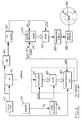
- an 8-pole sensor unit 20 is provided in the transmission of the vehicle for sensing rotational speed of the axle or transaxle, which is directly proportional to the speed of the wheels driving the vehicle.
- a VRS (variable reluctance sensor) input of the type used in an antilock braking system is capable of being processed by the system in accordance with the first preferred embodiment. While the frequency of the VRS sensor signal is approximately 6.9 Hz/Km h -1 (11.11 Hz/mph), the preferred embodiment uses the 8-pole sensor which provides a frequency of 1.38 Hz/Km h -1 (2.22 Hz/mph). This frequency is designated as F(in) at the conductor connecting the sensor 20 to the input of a timing generator 30.
- each leading edge of the input signal from the sensor 20 will generate a latch signal that will cause a latch 40 to fetch the value from the up counter 35 and to retain it within the latch 40.
- the leading edge of the input signal will then cause the timing generator 30 to send a clear signal which will reset the value of the up counter 35 to zero.
- F(in) 50% duty cycle
- each edge, rising and falling could be used in the timing generator effectively doubling the input frequency. This could prove beneficial in optimizing the accuracy or response characteristics.
- the up counter 35 accumulates the counts from a 62,500 Hz signal that is developed by taking the 4 MHz output from the master clock 60 and processing it through a divide by 64 counter 70. After the up counter 35 is cleared, it accumulates the clock pulses until the accumulated value is transferred to the latch 40, which occurs when the next positive edge of the input signal is detected by the timing generator 30. The value in the up counter 35 is then transferred to the latch 40, and the value in latch 40 is transferred to the down counter 50. In the same manner the down counter 50 will proceed to count downward from the value transferred from the latch 40 in the previous step, but at a clock rate of 4 MHz which is derived directly from the master clock 60. It should be apparent that the countdown in the down counter 50 will precede exactly 64 times faster than the accumulation of the pulses in the up counter 35 due to the ratio of the clock frequencies.
- the down counter 50 When the down counter 50 reaches zero for the first time, it sends an output pulse from the out port to a first input 101 of a gauge counter 100. At the same time, the output pulse from the down counter 50 triggers a load signal into another input of the down counter 50 which in turn causes the previous value of the latch 40 to be down loaded into the down counter 50.
- the down counter 50 counts down at the rate of 4 MHz, and thereby generates an output having the form of a series of pulses that occur exactly 64 times the frequency of the input signal from the sensor 20.
- the frequency multiplier (which includes the up counter 35, the latch 40, and the down counter 50) is more fully described in U.S. Patent 3,832,640 which is assigned to the owner of the present invention.
- the resulting output signal from the frequency multiplier occurs at a rate which is equal to the frequency of the input signal multiplied by the desired multiplier factor.
- the period during which the up counter 35 accumulates pulses from the 62.5 kHz clock, and during which the down counter 50 counts downward at a 4 MHz clock rate is equal to the period (one over the frequency) of the input signal from the sensor 20.
- the signal at the input 101 of the gauge counter 100 is counted at a clock rate provided by the down counter reaching zero or 64x F(in), and varies directly in relationship to the vehicle speed.
- the value in the gauge counter 100 is latched in latch 110 at a rate that varies according to the system parameters programmed for the particular embodiment utilized in the vehicle.
- the latch input frequency is determined by taking the 4 MHz signal from the master clock 60 and dividing that signal in the divider 80 by a factor of 256.
- the output from the divider 80 is then divided again in divider 90 by a constant N.
- the value for the constant N varies in each embodiment directly in accordance with the maximum degrees of sweep for the pointer in the analog gauge, and inversely in accordance with the maximum speed to be displayed (which will correspond to the maximum deviation of the pointer on the analog gauge). Since the divide by N counter 90 is a 10 bit counter, the maximum deflection of an analog gauge (360) will correspond to the maximum number of bits discernible by the counter 90 (1024 bits). Since 1024 bits is equal to 360, the value of N is directly proportional to the arc swept by the pointer of the analog gauge. In this manner if the desired deflection of the analog gauge is 180 (360 divided by 2), then the value of N must be 1024 bits divided by 2 or 512 bits. This results in a resolution of .35/bit.
- N 313 x SWEEP SPEED max
- the series of pulses from the output of the counter 90 will be translated to the input 110 of the latch 110 and the clear or set of the gauge counter 100, and each pulse at the input will define the period of time during which the clock pulses from the down counter 50 are accumulated.
- the period time during which the clock pulses are counted is a variable that is determined for each embodiment depending upon the number of degrees of arc swept by the pointer in the air-core gauge for full scale deflection and maximum indicated speed.
- the present value of clock pulses accumulated within the counter 100 will be frozen and transferred to a latch 110.
- the counter 100 is then cleared. Therefore, the value retained in the latch 110 will be a digital representation of the speed of the vehicle and will be updated at least every 40 milliseconds.
- the digital value within the latch 110 can be processed in several ways, including as a PWM signal, as a sine/cosine signal using ROMs and DACs, a tangential DAC, or as in the preferred embodiment as a tangent ROM and linear DAC (with the 10 bit value being split into a 3 bit octant decoder and a 7 bit (0-127) ROM address). It also would be possible to take the output of the latch 110 and transfer it directly to drive a digital display.
- the output of the tangential D/A converter 120 is coupled to analog drivers 130 that amplify and condition the signal and then apply it to an air-core gauge 140 having a movable pointer 144 thereon.
- the pointer 144 traverses an arc starting at zero and ending at full scale 100. This sweep defines an arc of approximately 270 in the preferred embodiment.
- Other air-core gauge models may be utilized having sweep arcs of 90, 180 and as much as 360, or any intermediate value determined by N.
- counter 70 may be incorporated within counter 80 and counters 80 and 90 may be concatenated to provide more programmability (i.e. N less than or equal to 183175), thus providing a finer resolution at the expense of a larger value for N, thereby requiring a larger number of programming bits to be available.
- FIG. 2 illustrates a more detailed representation of improvements made to the first preferred embodiment.
- Another divider 150 is inserted in the signal line 22between the sensor 20 and the timing generator 30 for dividing the frequency of the input signal by another constant K, which in the first preferred embodiment is equal to eight.
- K which in the first preferred embodiment is equal to eight.
- the constant eight was chosen in order to reduce the potential for frequency modulation in the 8-pole sensor signal from the transmission of the vehicle, such as could be caused by unequal spacing of the pole pieces in the sensing element. Therefore, instead of having eight pulses per revolution of the shaft being sensed, the output signal on line 23 from the divider 150 will have the frequency of Fn divided by K.
- the divider 150 is not actuated until the output from latch 40 exceeds approximately 27 mph, at which time a logic element 155 will enable the divider 150 to begin operation. This ensures adequate response at low speeds where the input frequency is low, but filters the signal at speeds where frequency modulation would be objectionable.
- the output of logic element 155 changes the operation of the divider 70 from a divide by 64 function to a divide by 64 times K (or the equivalent of a divide by 512 function). Since the output of divider 70 is coupled to up converter 30, the effect of dividing the input signal frequency by K in divider 150 will be cancelled out by dividing the clock frequency by eight in divider 70, and F(out) will equal 64 F(in) for all cases.
- This divider 150 is enabled at a speed greater than 27 mph in order to minimize any frequency modulation that may occur in the signal from the sensor 20 due to the uneven spacing of the eight poles about the rotational axis.
- the function of the calibration offset 160 can be explained as follows. First, the input from sensor 20 is set at a simulated speed of 60 mph, and the position of the pointer 144 on the analog gauge 140 is noted. Any deviation of the pointer from the intended 60 mph mark is cancelled by inserting a static offset value from the calibration offset 160 into the counter 100 at the start of the counting period. If the position of the pointer 144 is less than 60 mph, a positive calibration offset is inserted in order to advance the pointer to the correct value at the end of the period counted by the down counter 50. The value of the static calibration offset 160 can absorb any accumulation of errors or offsets within the electronics or the mechanical portions of the gauge 140.
- these offset calibrations are programmed by using high current pulses for trimming internal polysilicon resistors in the IC containing these digital circuits, which is a custom ASIC manufactured by Philips/Signetics.
- the polysilicon resistor values are sensed and decoded to provide the desired constants.
- a serial data input is used in this process.
- the polysilicon resistors are programmed at the final system manufacturing location through the use of a current loop in a serial data interface. This programming method minimizes chip area and pin count.
- the programming of could be accomplished by several different methods, including internal programmable fuses, EEPROMS, EPROMS, external pins, or any other method that provides for the programming of similar variables.
- a power down sequencer 170 is coupled to both the gauge counter 100 and the latch 110 for use when powering down the system. Assume first that the gauge is presently deflected 200 from the zero point. Normal gauges would utilize spring tension or some other reverse biasing means to return the pointer to the zero position when power is removed, but these biasing means cause nonlinearities in the normal operation of the gauge and significantly reduce the efficiency of the mechanism. The present invention does not use such reverse biasing means, but instead uses the power down sequencer 170 to sense the withdrawal of power from the system. At powerdown the sequencer 170 transfers the value from the latch 110 into the counter 100, and then changes the counter 100 from an up counter to a down counter. A fast clock signal then is used to count down from the last latch value to zero.
- the latch is transparent so that its output follows the counter values and drives the gauge directly. .
- the output of the latch 110 is used by the tangential D/A converter 120 and the analog drivers 130 to drive the pointer 144 to zero.
- the clock rate may be adjusted so that the rate of movement of the pointer 144 toward the zero stop approaches the maximum speed of movement of the pointer.
- the divider 150 (divide by K) is implemented in the preferred embodiment as a divide by 8 function.
- the signal from the sensor 22 is also directed to the input of a divider 156 that is implemented as a divide by 5 circuit.
- An input of a multiplexor 157 is coupled to the output of the divider 156 and the output of the divider 150 in order to provide a programmable switch for incrementing the output signal to an odometer 158. If the mux 157 is selected to the output of the divider 150 (divide by 8), then the signal to the odometer 158 is 1000 pulses per mile. If the mux 157 is selected to the output of the divider 156 (divide by 5), then output is 1000 pulses /km. In the event that the filter is not needed or is a value other than 8, a separate divide by 8 circuit would be required. An alternative would be to use a single counter that could divide by either 8 or 5 according to a selectable, programmable input signal.
- the preferred embodiment of the present invention may be modified in order to operate as a tachometer rather than a speedometer and odometer.
- the sensor 20 is replaced by a direct signal from either an electronic engine control unit or an ignition control unit, with the signal being directly proportional to the firing of the spark plugs in the engine.
- a programmable divider circuit would be substituted for divider 70 that is coupled to the latch 40.
- the divider 70 would be adjusted to divide by 60, 80 or 120 depending on whether the number of cylinders was 8, 6 or 4, rather than the divide by 64 that was utilized in the speedometer.
- N 22,222 x SWEEP RPM max This value of N may be adjusted depending upon the maximum value of the rpm signal expected and the sweep available in the air-core gauge.
- the speedometer In the preferred design of the speedometer the lowest speed registered is 3.4 mph, with a resolution of 1.4 mph at 200 mph, and an update rate of .064N ms.
- the preferred embodiment for the tachometer is slightly different since the signals representative of the engine rpm are of significantly higher frequency than the signals representative of the speed of the vehicle.
- the lowest rpm registered is 228 rpm, with a resolution of 72 rpm at 8,000 rpm, and an update time of .034N ms. It should be recognized that by selecting the appropriate values of N, the speedometer could also be calibrated in km/hr, and other engines (e.g. 10 or 12 cylinders) could be accommodated by the circuits utilized in the preferred embodiment.
Landscapes
- Physics & Mathematics (AREA)
- General Physics & Mathematics (AREA)
- Measuring Frequencies, Analyzing Spectra (AREA)
- Instrument Panels (AREA)
- Indication And Recording Devices For Special Purposes And Tariff Metering Devices (AREA)
Claims (13)
- Procédé destiné à améliorer la vitesse de réponse et l'exactitude de l'affichage d'un dispositif de mesure utilisé pour mesurer la fréquence d'un signal d'entrée périodique présentant une fréquence largement variable, le procédé comprenant les étapes consistant à :caractérisé en ce que le procédé comprend les étapes supplémentaires consistant à :recevoir le signal en entrée,générer un signal intermédiaire en multipliant la fréquence du signal en entrée par une première constante, etcompter la fréquence du signal intermédiaire pendant un intervalle de temps donné afin d'obtenir un comptage représentatif de la fréquence du signal en entrée,appliquer ledit comptage de la fréquence du signal intermédiaire à un indicateur analogique qui présente une déviation du dispositif de mesure proportionnelle à la fréquence intermédiaire comptée dans les limites d'un arc de déviation de balayage maximum,déterminer une seconde constante qui lie ledit arc de déviation maximum à une fréquence maximum prévue du signal en entrée, etétablir ledit intervalle de temps pour qu'il soit directement proportionnel audit arc de déviation de balayage maximum multiplié par la seconde constante et inversement proportionnel à la fréquence prévue maximum du signal en entrée.
- Procédé selon la revendication 1, comprenant en outre l'étape préliminaire consistant à ajuster lesdites première et seconde constantes de façon à obtenir la déviation de balayage maximum sur l'indicateur à la fréquence prévue maximum du signal en entrée.
- Procédé selon la revendication 1 ou 2, comprenant l'étape supplémentaire consistant à étalonner l'indicateur vis-à-vis de tout décalage statique par rapport à la valeur désirée en comptant la fréquence du signal intermédiaire en commençant avec une constante de décalage élaborée de façon à annuler le décalage statique.
- Procédé selon la revendication 1, 2 ou 3, suivi d'une étape d'arrêt comprenant :
l'arrêt du comptage de la fréquence du signal intermédiaire et son remplacement par un décompte jusqu'à zéro à partir de la dernière fréquence intermédiaire, d'où il résulte que l'indicateur diminuera depuis la dernière valeur affichée jusqu'à zéro. - Procédé selon la revendication 4, dans lequel la vitesse du décompte est cadencée à une vitesse rapide qui reste dans les limites du temps de réponse de l'indicateur, d'où il résulte que l'indicateur se rapproche de zéro à une vitesse qui se rapproche du temps de réponse maximum du mouvement de l'indicateur.
- Procédé selon l'une quelconque des revendications précédentes, dans lequel l'étape consistant à générer ledit signal intermédiaire comprend l'étape consistant à réduire la fréquence du signal en entrée grâce à l'utilisation d'un diviseur de fréquence et également à réduire la fréquence des impulsions d'horloge utilisées pour générer ladite première constante grâce à un diviseur correspondant.
- Procédé selon l'une quelconque des revendications précédentes lorsqu'il est appliqué à la détection de la rotation d'un arbre au moyen d'un capteur présentant un nombre prédéterminé de pôles de capteur, dans lequel l'étape consistant à générer ledit signal intermédiaire comprend également l'étape consistant à diviser la fréquence du signal en entrée par une constante égale au nombre des pôles du capteur, et comprenant en outre l'étape consistant à diviser la fréquence du signal intermédiaire résultante par la même constante.
- Système destiné à afficher la fréquence d'un signal périodique en entrée présentant une fréquence largement variable, le système comprenant :caractérisé en ce que :un dispositif de mesure (140),un moyen de multiplication de fréquence (35, 40, 50) destiné à recevoir et à multiplier la fréquence du signal en entrée par une première constante afin de générer un signal intermédiaire, etun moyen de comptage (100) couplé audit moyen de multiplication de fréquence, destiné à compter la fréquence du signal intermédiaire pendant un intervalle de temps donné afin d'obtenir un comptage représentatif de la fréquence du signal en entrée,le dispositif de mesure est un indicateur analogique (140) qui présente une déviation de dispositif de mesure qui est proportionnel au comptage du moyen de comptage (100) dans les limites d'un arc de déviation de balayage maximum, et le système comprend en outre,un moyen (80, 90) qui peut être réglé pour amener le moyen de comptage (100) à compter pendant un intervalle de temps qui peut être sélectionné pour être directement proportionnel à l'arc de déviation de balayage maximum du dispositif de mesure multiplié par une seconde constante et inversement proportionnel à la fréquence maximum prévue du signal en entrée.
- Système selon la revendication 8, dans lequel les première et seconde constantes sont sélectionnées de façon à ce que la déviation de balayage maximum sur l'indicateur (100) soit obtenue à la fréquence maximum prévue du signal en entrée.
- Système selon la revendication 9, dans lequel un moyen est prévu pour faire varier des résistances intégrées au moyen de comptage afin de sélectionner les première et seconde constantes.
- Système selon la revendication 8, 9 ou 10, dans lequel l'indicateur (140) est un indicateur à noyau à air.
- Système selon la revendication 8,9,10 ou 11, qui est adapté pour afficher la fréquence d'un signal en entrée qui varie en fréquence de 0 Hz à 600 Hz.
- Système selon la revendication 8, 9, 10, 11 ou 12, qui est adapté pour fonctionner soit comme compteur de vitesse, soit comme compte-tours.
Applications Claiming Priority (2)
| Application Number | Priority Date | Filing Date | Title |
|---|---|---|---|
| US08/001,610 US5357451A (en) | 1993-01-07 | 1993-01-07 | Digital system controller with programmable ranges for analog speedometer and tachometer gauges |
| US1610 | 2001-10-30 |
Publications (2)
| Publication Number | Publication Date |
|---|---|
| EP0609624A1 EP0609624A1 (fr) | 1994-08-10 |
| EP0609624B1 true EP0609624B1 (fr) | 1998-06-10 |
Family
ID=21696965
Family Applications (1)
| Application Number | Title | Priority Date | Filing Date |
|---|---|---|---|
| EP93310344A Expired - Lifetime EP0609624B1 (fr) | 1993-01-07 | 1993-12-20 | Appareil de contrÔle de système digital comprenant des plages programmables pour indicateurs analogiques de compteurs de vitesse et de tachymètres |
Country Status (3)
| Country | Link |
|---|---|
| US (1) | US5357451A (fr) |
| EP (1) | EP0609624B1 (fr) |
| DE (1) | DE69319084D1 (fr) |
Cited By (1)
| Publication number | Priority date | Publication date | Assignee | Title |
|---|---|---|---|---|
| SG129338A1 (en) * | 2005-07-25 | 2007-02-26 | Sin Etke Technology Co Ltd | Speedometer and motor vehicle arrangement |
Families Citing this family (14)
| Publication number | Priority date | Publication date | Assignee | Title |
|---|---|---|---|---|
| US5475724A (en) * | 1994-07-29 | 1995-12-12 | Liu; Paul | Speedometer/odometer apparatus |
| KR0136285Y1 (ko) * | 1996-07-05 | 1999-03-30 | 김광호 | 신호펄스간의 시간측정기능을 갖는 카운터 제어장치 |
| US6073087A (en) * | 1996-11-20 | 2000-06-06 | Philips Electronics North America Corporation | Digital tachometer |
| US6219624B1 (en) | 1998-08-03 | 2001-04-17 | Visteon Global Technologies, Inc. | Synchronous timer vehicle speed measurement |
| US6216062B1 (en) * | 1999-11-11 | 2001-04-10 | Visteon Global Technologies, Inc. | Step-less vehicle display allowing irregular update intervals |
| KR100456964B1 (ko) * | 2001-10-19 | 2004-11-10 | 기아자동차주식회사 | 차속신호 변환방법 |
| FR2846462A1 (fr) * | 2002-10-28 | 2004-04-30 | St Microelectronics Sa | Compteur monotone croissant en circuit integre |
| US20040104816A1 (en) * | 2002-12-02 | 2004-06-03 | Daimlerchrysler Corporation | Tachometer redline display |
| US20050151633A1 (en) * | 2003-10-29 | 2005-07-14 | De Sisti Lighting S.P.A. | Electronic gauge translator for ECU equipped engines |
| US7538662B2 (en) * | 2005-10-04 | 2009-05-26 | Innovate! Technology, Inc. | Programmable vehicle gauge apparatus, system, and method |
| US8669856B2 (en) * | 2010-11-23 | 2014-03-11 | Honda Motor Co., Ltd. | Method to calibrate digital speedometer display to meter speedometer display |
| JP2012147568A (ja) * | 2011-01-12 | 2012-08-02 | On Semiconductor Trading Ltd | モータ速度制御回路 |
| US20130226500A1 (en) * | 2012-02-27 | 2013-08-29 | Yazaki North America, Inc. | Determination of validity of bi-level digital signal via digital data acquisition |
| US20250292637A1 (en) * | 2024-03-18 | 2025-09-18 | Ohio INTX Cooperative | System, method, and device for converting digital data from a controller area network chip to analog signals for display on a vehicle gauge |
Family Cites Families (26)
| Publication number | Priority date | Publication date | Assignee | Title |
|---|---|---|---|---|
| US3832640A (en) * | 1972-12-11 | 1974-08-27 | Ford Motor Co | Time division interpolator |
| US3946311A (en) * | 1973-06-11 | 1976-03-23 | Stewart-Warner Corporation | Air core gauge with expanded pointer range |
| US4167699A (en) * | 1977-03-25 | 1979-09-11 | Stewart-Warner Corporation | User calibrated electronic speedometer and odometer |
| US4268792A (en) * | 1977-06-22 | 1981-05-19 | Caterpillar Tractor Co. | Method of and apparatus for multiplying pulses |
| US4199719A (en) * | 1977-06-22 | 1980-04-22 | Caterpillar Tractor Co. | Instrument for measuring the speed in RPM of a rotating gear |
| US4140970A (en) * | 1977-09-08 | 1979-02-20 | Sangamo Weston, Inc. | Apparatus for controlling an odometer and speedometer system of a vehicle |
| NL7711634A (nl) * | 1977-10-24 | 1979-04-26 | Philips Nv | Tachometerstelsel. |
| US4230984A (en) * | 1979-03-22 | 1980-10-28 | General Motors Corporation | Method and apparatus for driving an air core gage |
| US4350952A (en) * | 1979-11-05 | 1982-09-21 | Outboard Marine Corporation | Digital read-out meter circuit and tachometer with variable meter update rate using an up/down counter means |
| US4356445A (en) * | 1980-07-10 | 1982-10-26 | Cherry Semiconductor Corporation | Method and apparatus for driving air core meter movements |
| JPS5753664A (en) * | 1980-09-18 | 1982-03-30 | Nippon Air Brake Co Ltd | Arithmetic circuit for wheel turning speed |
| JPS58127294A (ja) * | 1982-01-26 | 1983-07-29 | 株式会社東芝 | デイジタル移動検出装置 |
| US4491007A (en) * | 1982-12-02 | 1985-01-01 | Beede Electrical Instrument Co., Inc. | Rangeable speedometer/odometer |
| FR2583166B1 (fr) * | 1985-06-07 | 1988-04-15 | Jaeger | Dispositif de mesure de la vitesse de deplacement d'un vehicule |
| US4779213A (en) * | 1987-05-27 | 1988-10-18 | Chrysler Motors Corporation | Electronic digital speedometer for a multi-measurand data communication system |
| US4939659A (en) * | 1988-01-15 | 1990-07-03 | Allied-Signal, Inc. | Speed/rpm transmitting device |
| JPH0711538B2 (ja) * | 1988-02-05 | 1995-02-08 | ジェコー株式会社 | 交差コイル式計器の駆動回路 |
| US4918629A (en) * | 1988-04-07 | 1990-04-17 | The Boeing Company | Engine trim tachometer unit and calibration method |
| US4988944A (en) * | 1988-08-12 | 1991-01-29 | Jeco Company Limited | Cross coil type instrument |
| JPH0675077B2 (ja) * | 1988-11-24 | 1994-09-21 | ローム株式会社 | メータ駆動装置 |
| US4939675A (en) * | 1988-12-22 | 1990-07-03 | Chrysler Corporation | Digital system for controlling mechanical instrument gauges |
| US5105150A (en) * | 1989-06-29 | 1992-04-14 | Paul Liu | Wide-band programmable tachometer and speedometer/odometer apparatus |
| US5018087A (en) * | 1989-11-03 | 1991-05-21 | Navistar International Transportation Corp. | Programming signal source and calibration data for a speedometer/tachometer with calibration switches |
| US5001930A (en) * | 1989-11-06 | 1991-03-26 | Acustar, Inc. | Speedometer assembly |
| US5063344A (en) * | 1990-03-05 | 1991-11-05 | Delco Electronics Corporation | Mode selectable interface circuit for an air core gage controller |
| JPH0820456B2 (ja) * | 1990-03-12 | 1996-03-04 | 矢崎総業株式会社 | 車速計測方法及び装置 |
-
1993
- 1993-01-07 US US08/001,610 patent/US5357451A/en not_active Expired - Fee Related
- 1993-12-20 EP EP93310344A patent/EP0609624B1/fr not_active Expired - Lifetime
- 1993-12-20 DE DE69319084T patent/DE69319084D1/de not_active Expired - Lifetime
Cited By (1)
| Publication number | Priority date | Publication date | Assignee | Title |
|---|---|---|---|---|
| SG129338A1 (en) * | 2005-07-25 | 2007-02-26 | Sin Etke Technology Co Ltd | Speedometer and motor vehicle arrangement |
Also Published As
| Publication number | Publication date |
|---|---|
| DE69319084D1 (de) | 1998-07-16 |
| EP0609624A1 (fr) | 1994-08-10 |
| US5357451A (en) | 1994-10-18 |
Similar Documents
| Publication | Publication Date | Title |
|---|---|---|
| US4167699A (en) | User calibrated electronic speedometer and odometer | |
| US5357451A (en) | Digital system controller with programmable ranges for analog speedometer and tachometer gauges | |
| US4470011A (en) | Electric type tachometer for vehicles | |
| CA2005700C (fr) | Programmation d'un signal source et donnees d'etalonnage pour un tachymetre/compte-tours avec interrupteurs d'etaqlonnage | |
| US3739270A (en) | Electronic speedometer/odometer with interchangeable calibrating means for accommodating a plurality of vehicle tire sizes | |
| CN1088834C (zh) | 步进电动机式计量仪的驱动装置 | |
| CN1088832C (zh) | 步进电机式仪表驱动装置 | |
| US4227150A (en) | System for indicating measured values | |
| US4742297A (en) | Programmable cycle meter | |
| US5446655A (en) | Multiple-meter driving apparatus | |
| US6801838B2 (en) | Device and method for converting vehicle speed signals | |
| US5869776A (en) | Method and apparatus for receiving and displaying digital data | |
| KR960005344B1 (ko) | 속도/회전수 전송장치 | |
| US4200812A (en) | Frequency converter delivering constant width output pulses within variable duty cycles | |
| US4144573A (en) | Metering system | |
| US4310801A (en) | Programmable divider | |
| GB2179159A (en) | A method of displaying the speed and distance travelled by a motor vehicle | |
| US5698974A (en) | Robust gauge driving circuit with pulse modulated input | |
| US5448163A (en) | Meter drive including a timer for generating update cycles at a frequency larger than the input clock pulses and digital filtering | |
| US4361066A (en) | Tempo measurement, display, and control system for an electronic musical instrument | |
| JP2000018975A (ja) | ステッピングモータ式計器装置 | |
| JP3456138B2 (ja) | 車速検出装置 | |
| JP3224009B2 (ja) | 指針式表示装置 | |
| US4629981A (en) | Meter overdrive protection circuit | |
| JP2559122B2 (ja) | 車両用走行距離計 |
Legal Events
| Date | Code | Title | Description |
|---|---|---|---|
| PUAI | Public reference made under article 153(3) epc to a published international application that has entered the european phase |
Free format text: ORIGINAL CODE: 0009012 |
|
| AK | Designated contracting states |
Kind code of ref document: A1 Designated state(s): DE ES FR GB PT |
|
| 17P | Request for examination filed |
Effective date: 19950113 |
|
| 17Q | First examination report despatched |
Effective date: 19960718 |
|
| GRAG | Despatch of communication of intention to grant |
Free format text: ORIGINAL CODE: EPIDOS AGRA |
|
| GRAG | Despatch of communication of intention to grant |
Free format text: ORIGINAL CODE: EPIDOS AGRA |
|
| GRAH | Despatch of communication of intention to grant a patent |
Free format text: ORIGINAL CODE: EPIDOS IGRA |
|
| GRAH | Despatch of communication of intention to grant a patent |
Free format text: ORIGINAL CODE: EPIDOS IGRA |
|
| GRAA | (expected) grant |
Free format text: ORIGINAL CODE: 0009210 |
|
| AK | Designated contracting states |
Kind code of ref document: B1 Designated state(s): DE ES FR GB PT |
|
| PG25 | Lapsed in a contracting state [announced via postgrant information from national office to epo] |
Ref country code: FR Free format text: LAPSE BECAUSE OF FAILURE TO SUBMIT A TRANSLATION OF THE DESCRIPTION OR TO PAY THE FEE WITHIN THE PRESCRIBED TIME-LIMIT Effective date: 19980610 Ref country code: ES Free format text: THE PATENT HAS BEEN ANNULLED BY A DECISION OF A NATIONAL AUTHORITY Effective date: 19980610 |
|
| REF | Corresponds to: |
Ref document number: 69319084 Country of ref document: DE Date of ref document: 19980716 |
|
| PG25 | Lapsed in a contracting state [announced via postgrant information from national office to epo] |
Ref country code: DE Free format text: LAPSE BECAUSE OF FAILURE TO SUBMIT A TRANSLATION OF THE DESCRIPTION OR TO PAY THE FEE WITHIN THE PRESCRIBED TIME-LIMIT Effective date: 19980911 |
|
| PG25 | Lapsed in a contracting state [announced via postgrant information from national office to epo] |
Ref country code: PT Free format text: LAPSE BECAUSE OF FAILURE TO SUBMIT A TRANSLATION OF THE DESCRIPTION OR TO PAY THE FEE WITHIN THE PRESCRIBED TIME-LIMIT Effective date: 19980915 |
|
| EN | Fr: translation not filed | ||
| PLBE | No opposition filed within time limit |
Free format text: ORIGINAL CODE: 0009261 |
|
| STAA | Information on the status of an ep patent application or granted ep patent |
Free format text: STATUS: NO OPPOSITION FILED WITHIN TIME LIMIT |
|
| 26N | No opposition filed | ||
| REG | Reference to a national code |
Ref country code: GB Ref legal event code: IF02 |
|
| PGFP | Annual fee paid to national office [announced via postgrant information from national office to epo] |
Ref country code: GB Payment date: 20041213 Year of fee payment: 12 |
|
| PG25 | Lapsed in a contracting state [announced via postgrant information from national office to epo] |
Ref country code: GB Free format text: LAPSE BECAUSE OF NON-PAYMENT OF DUE FEES Effective date: 20051220 |
|
| GBPC | Gb: european patent ceased through non-payment of renewal fee |
Effective date: 20051220 |