EP0609676B1 - Spritzgiessdüse mit Thermoelementrohr - Google Patents
Spritzgiessdüse mit Thermoelementrohr Download PDFInfo
- Publication number
- EP0609676B1 EP0609676B1 EP94100455A EP94100455A EP0609676B1 EP 0609676 B1 EP0609676 B1 EP 0609676B1 EP 94100455 A EP94100455 A EP 94100455A EP 94100455 A EP94100455 A EP 94100455A EP 0609676 B1 EP0609676 B1 EP 0609676B1
- Authority
- EP
- European Patent Office
- Prior art keywords
- nozzle
- thermocouple
- central portion
- extending
- injection molding
- Prior art date
- Legal status (The legal status is an assumption and is not a legal conclusion. Google has not performed a legal analysis and makes no representation as to the accuracy of the status listed.)
- Expired - Lifetime
Links
Images
Classifications
-
- B—PERFORMING OPERATIONS; TRANSPORTING
- B29—WORKING OF PLASTICS; WORKING OF SUBSTANCES IN A PLASTIC STATE IN GENERAL
- B29C—SHAPING OR JOINING OF PLASTICS; SHAPING OF MATERIAL IN A PLASTIC STATE, NOT OTHERWISE PROVIDED FOR; AFTER-TREATMENT OF THE SHAPED PRODUCTS, e.g. REPAIRING
- B29C45/00—Injection moulding, i.e. forcing the required volume of moulding material through a nozzle into a closed mould; Apparatus therefor
- B29C45/17—Component parts, details or accessories; Auxiliary operations
- B29C45/26—Moulds
- B29C45/27—Sprue channels ; Runner channels or runner nozzles
-
- B—PERFORMING OPERATIONS; TRANSPORTING
- B29—WORKING OF PLASTICS; WORKING OF SUBSTANCES IN A PLASTIC STATE IN GENERAL
- B29C—SHAPING OR JOINING OF PLASTICS; SHAPING OF MATERIAL IN A PLASTIC STATE, NOT OTHERWISE PROVIDED FOR; AFTER-TREATMENT OF THE SHAPED PRODUCTS, e.g. REPAIRING
- B29C45/00—Injection moulding, i.e. forcing the required volume of moulding material through a nozzle into a closed mould; Apparatus therefor
- B29C45/17—Component parts, details or accessories; Auxiliary operations
- B29C45/26—Moulds
- B29C45/27—Sprue channels ; Runner channels or runner nozzles
- B29C45/2737—Heating or cooling means therefor
- B29C2045/274—Thermocouples or heat sensors
Definitions
- This invention relates generally to injection molding and more particularly to a heated nozzle having a tube for removably receiving a thermocouple element extending along the inner surface of a cylindrical locating flange where it is spaced from the outer surface of the central portion of the nozzle.
- thermocouple element Mounting a heated injection molding nozzle in a well in a cooled mold with an insulative air space between them is well known. It is also known to run a thermocouple element through the air space to monitor the operating temperature near the forward end of the nozzle. An example of this is shown in the applicant's U.S. patent number 4,583,284 which issued April 22, 1986 where the thermocouple element extends into the insulative air space through an opening in the mold. Another example is seen in the applicant's U.S. patent number 4,768,283 which issued September 6, 1988 where the thermocouple element extends into the insulative air space through a thermocouple bore extending forwardly through the rear collar portion of the nozzle.
- thermocouple tube which prevents the leakage of melt along the thermocouple element.
- the invention provides an injection molding nozzle to be mounted in a well in a cooled mold, the nozzle having a rear end, a forward end, a rear collar portion adjacent to the rear end, and a central portion extending forwardly from the rear collar portion, the central portion having a generally cylindrical outer surface and the rear collar portion being larger in diameter than the central portion, the nozzle having a melt channel extending therethrough to convey melt from an inlet at the rear end towards at least one gate extending through the mold to a cavity, the nozzle having an integral electrical heating element with a spiral portion extending around at least a portion of the melt channel, the nozzle having a cylindrical locating flange extending a predetermined distance forwardly from the rear collar portion around the central portion, the locating flange having an inner surface spaced from the outer surface of the central portion by an insulative space having a predetermined width, the rear collar portion of the nozzle having a thermocouple bore extending therethrough from the rear end to the insulative space between
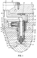
- FIG. 1 shows a portion of a multi-cavity injection molding system having several steel nozzles 10 to convey pressurized plastic melt to respective gates 12 leading to different cavities 14 in the mold 16.
- Each nozzle 10 has a thermocouple tube 18 through which a thermocouple element 20 extends according to the invention.
- the mold includes a cavity plate 22, and a back plate 24 which are removably secured together by bolts 26.
- the mold 16 is cooled by pumping cooling water through cooling conduits 28 extending in the cavity plate 22, and the back plate 24.
- An electrically heated steel melt distribution manifold 30 is mounted between the cavity plate 22 and the back plate 24 by a central locating ring 32 and insulative and resilient spacer members 34.
- the melt distribution manifold 30 has a cylindrical inlet portion 36 and is heated by an integral electrical heating element 38.
- An insulative air space 40 is provided between the heated manifold 30 and the surrounding cooled cavity plate 22, and back plate 24.
- a melt passage 42 extends from a common inlet 44 in the inlet portion 36 of the manifold 30 and branches outward in the manifold 30 to each nozzle 10 where it extends through a central melt channel 46 to one of the gates 12.
- Each nozzle 10 has a rear end 48, a forward end 50, a rear collar portion 52 adjacent the rear end 48, and a central portion 54 which extends forwardly from the rear collar portion 52.
- the central portion 54 has a generally cylindrical outer surface 56, and the rear collar portion 52 is larger in diameter than the central portion 54.
- the nozzle 10 is heated by an integral electrical heating element 58 which has a spiral portion 60 extending around the melt channel 46 and an external terminal 62 to which electrical leads 64 from a power source are connected.
- the nozzle 10 is seated in a well 66 in the cavity plate 22 with a cylindrical locating flange 68 extending a predetermined distance forwardly from the collar portion 52 to a circular locating shoulder 70 in the well 66.
- the locating flange 68 has an inner surface 72 which is spaced from the outer surface 56 of the central portion 54 by an insulative air space 74 which also extends between the heated central portion 54 of the nozzle 10 and the surrounding cooled cavity plate 22.
- melt channel 46 extends centrally from the rear end 48 to a torpedo 76 which is seated in the forward end 50 in alignment with one of the gates 12.
- a hollow nozzle seal 78 is seated in the cavity plate 22 around the gate 12 to retain the torpedo 76 in place and prevent melt leaking into the air space 74.
- nozzles 10 to provide other types of gating will have different configurations.
- the melt distribution manifold 30 and the nozzles 10 are securely retained in this position against the melt injection pressure by the space members 34 and also by bolts 80 which extend from the manifold 30 into the cavity plate 22.
- the nozzle 10 has a thermocouple bore 82 which extends through the rear collar portion 52 from the rear end 48 to the insulative air space 74 between the central portion 54 and the locating flange 68.
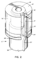
- the hollow thermocouple tube 18 which is made of stainless steel extends through the thermocouple bore 82 in the collar portion 52 and along the inner surface 72 of the locating flange 68.
- the thermocouple tube 18 can be mounted along the inner surface 72 of the locating flange 68 to extend directly from the thermocouple bore 82 in the collar portion 52 so that any melt which escapes into the air space 74 cannot leak between them.
- thermocouple tube 18 is partially seated in a groove 84 in the inner surface 72 of the locating flange 68.
- a nickel alloy brazing material is applied along it, and it is integrally brazed in place in a vacuum furnace at the same time as the other components of the nozzle are integrally brazed together.
- the thermocouple tube 18 removably receives the thermocouple element 20 which then runs through the air space 74 and into a suitable bore 86 to monitor the operating temperature near the forward end 50 of the nozzle 10.
- the relatively thin locating flange 68 is to some extent cooled by contact with the cooled cavity plate 22 against which it is located and seated.
- the contact of the thermocouple tube 18 with the locating flange 68 cools the melt which flows into the thermocouple tube 18 around the thermocouple element 20 sufficiently to freeze it and prevent leakage through the thermocouple tube 18.
- the outer surface 56 of the central portion 54 of the nozzle 10 is depressed adjacent the thermocouple tube 18 by having a channel 88 which extends in alignment with the thermocouple tube 18. This provides additional clearance between the thermocouple tube 18 and the central portion 54 of the nozzle 10 to avoid heat from the heated central portion 54 overcoming the cooling effect on the thermocouple tube 18 from the locating flange 68.
- the injection molding system is assembled as shown in Figure 1. While only a single cavity 14 has been shown for ease of illustration, it will be appreciated that the melt distribution manifold 30 normally has many more melt passage branches extending to numerous cavities 14 depending on the application. Electrical power is applied to the heating element 38 in the manifold 30 and to the heating elements 58 in the nozzles 10 to heat them to a predetermined operating temperature. Pressurized melt from a molding machine (not shown) is then injected into the melt passage 42 through the common inlet 44 according to a predetermined cycle in a conventional manner. The pressurized melt flows through the melt channels 46 of the respective nozzles 10 to the gates 12 to fill the cavities 14. After the cavities 14 are filled, injection pressure is held momentarily to pack and then released.
- the mold After a short cooling period, the mold is opened to eject the molded products. After ejection, the mold is closed and injection pressure is reapplied to refill the cavities 14. This cycle is continuously repeated with a frequency dependent on the size and shape of the cavities 14 and the type of material being molded. If the pressurized melt leaks past the nozzle seal 78 and fills the air space 74, it flows into the thermocouple tube 18 around the thermocouple element 20. However, the contact of the thermocouple tube 18 with the locating flange 68 cools the thermocouple tube 18 sufficiently to freeze the melt in the tube and prevent it escaping amongst the wiring in other parts of the mold.
Landscapes
- Engineering & Computer Science (AREA)
- Manufacturing & Machinery (AREA)
- Mechanical Engineering (AREA)
- Injection Moulding Of Plastics Or The Like (AREA)
- Moulds For Moulding Plastics Or The Like (AREA)
- Control Of Combustion (AREA)
Claims (6)
- Spritzgußdüse (10) zum Einbau in einen Einlauf einer gekühlten Form (16), wobei die Düse ein hinteres Ende (48), ein vorderes Ende (50), einen hinteren Bundabschnitt (52) neben dem hinteren Ende (48) und einen Mittelabschnitt (54), der sich von dem hinteren Bundabschnitt (52) nach vorne erstreckt, aufweist, wobei der Mittelabschnitt (54) eine im wesentliche zylindrische Außenfläche (56) aufweist und der hintere Bundabschnitt (52) einen größeren Durchmesser als der Mittelabschnitt (54) aufweist, wobei die Düse (10) weiterhin einen sich durch diese erstreckenden Schmelzenkanal (46) aufweist, um Schmelze von einem Einlaß (36) an dem hinteren Ende (48) zu wenigstens einem Einguß (12) zu fördern, der sich durch die Form zu einem Hohlraum (14) erstreckt, wobei die Düse (10) weiterhin ein integrales, elektrisches Heizelement (58) mit einem sich zumindest um einen Abschnitt des Schmelzenkanals (46) erstreckenden Spiralabschnitt aufweist, sowie einen zylindrischen Lageflansch (68), der sich in einem bestimmten Abstand von dem hinteren Bundabschnitt (52) nach vorne um den Mittelabschnitt (54) erstreckt, wobei der Lageflansch (68) eine Innenfläche (72) aufweist, die von der Außenfläche (56) des Mittelabschnittes (54) durch einen Isolierraum (54) vorgegebener Breite beabstandet ist, der hintere Bundabschnitt (52) der Düse (10) eine Thermoelementbohrung (82) aufweist, die sich durch diesen von dem hinteren Ende (48) zu dem Isolierraum (74) zwischen dem Mittelabschnitt (54) und dem Lageflansch (68) erstreckt, dadurch gekennzeichnet, daß die Düse (10) ein hohles Thermoelementrohr (18) aufweist, das sich von der Thermoelementbohrung (82) um einen vorbestimmten Abstand nach vorne entlang der Innenfläche des Lageflansches (68) erstreckt, um ein sich in den Isolierraum (74) erstreckendes Thermoelement (20) entfernbar aufzunehmen, wobei das Thermoelementrohr (18) in einem vorbestimmten Abstand von der Außenfläche (56) des Mittelabschnittes (54) der Düse (10) beabstandet ist.
- Spritzgußdüse (10) nach Anspruch 1, dadurch gekennzeichnet, daß das Thermoelmentrohr (18) sich weiterhin durch die Thermoelementbohrung (82) durch den hinteren Bundabschnitt (52) der Düse (10) erstreckt.
- Spritzgußdüse (10) nach Anspruch 2, dadurch gekennzeichnet, daß das Thermoelementrohr (18) zumindest teilweise in einer Nut (84) in der Innenfläche (72) des Lageflansches (68) der Düse sitzt.
- Spritzgußdüse (10) nach Anspruch 3, dadurch gekennzeichnet, daß das Thermoelementrohr (18) an seinem Platz integral angelötet ist.
- Spritzgußdüse (10) nach Anspruch 4, dadurch gekennzeichnet, daß die Außenfläche (56) des Mittelabschnittes (54) neben dem Thermoelementrohr (18) vertieft ist, um einen ausreichenden Zwischenraum zwischen beiden bereitzustellen.
- Spritzgußdüse (10) nach Anspruch 4, dadurch gekennzeichnet, daß die Außenfläche des Mittelabschnittes eine sich zu dem Thermoelementrohr (18) ausgerichtet erstreckende Rinne (88) aufweist, um einen ausreichenden Zwischenraum zwischen beiden bereitszustellen.
Applications Claiming Priority (2)
| Application Number | Priority Date | Filing Date | Title |
|---|---|---|---|
| CA002088228A CA2088228C (en) | 1993-01-27 | 1993-01-27 | Injection molding nozzle with thermocouple tube |
| CA2088228 | 1993-01-27 |
Publications (2)
| Publication Number | Publication Date |
|---|---|
| EP0609676A1 EP0609676A1 (de) | 1994-08-10 |
| EP0609676B1 true EP0609676B1 (de) | 1997-06-25 |
Family
ID=4151052
Family Applications (1)
| Application Number | Title | Priority Date | Filing Date |
|---|---|---|---|
| EP94100455A Expired - Lifetime EP0609676B1 (de) | 1993-01-27 | 1994-01-13 | Spritzgiessdüse mit Thermoelementrohr |
Country Status (7)
| Country | Link |
|---|---|
| EP (1) | EP0609676B1 (de) |
| JP (1) | JP3447353B2 (de) |
| CN (1) | CN1049858C (de) |
| AT (1) | ATE154780T1 (de) |
| CA (1) | CA2088228C (de) |
| DE (2) | DE4400816C2 (de) |
| ES (1) | ES2103090T3 (de) |
Families Citing this family (6)
| Publication number | Priority date | Publication date | Assignee | Title |
|---|---|---|---|---|
| CA2101480C (en) * | 1993-07-28 | 2001-09-11 | Jobst Ulrich Gellert | Injection molding nozzle which retains a thermocouple element |
| CA2102854C (en) * | 1993-11-10 | 2001-09-11 | Jobst Ulrich Gellert | Heated injection molding nozzle with alternate thermocouple bores |
| US7320765B2 (en) * | 2004-04-30 | 2008-01-22 | International Automotive Components Group North America, Inc. | Gas pin for thermocouple for gas assisted injection molding |
| DE202006006671U1 (de) * | 2006-04-21 | 2007-09-06 | Günther Heisskanaltechnik Gmbh | Heißkanaldüse |
| DE202008007918U1 (de) * | 2008-06-16 | 2009-11-19 | Günther Heisskanaltechnik Gmbh | Spritzgießdüse für ein Spritzgießwerkzeug |
| CN116927232B (zh) * | 2023-09-13 | 2023-11-28 | 启东晶尧光电科技有限公司 | 一种光伏电站的桩基础结构与桩基础施工工艺 |
Family Cites Families (5)
| Publication number | Priority date | Publication date | Assignee | Title |
|---|---|---|---|---|
| CA1230458A (en) * | 1984-07-13 | 1987-12-22 | Gellert, Jobst Ulrich | Injection molding heated nozzle with brazed in heating element and method of manufacture |
| CA1252970A (en) * | 1986-10-23 | 1989-04-25 | Mold-Masters Limited | Dual feed bushing for multi-cavity injection molding |
| CA1264009A (en) * | 1987-03-20 | 1989-12-27 | Jobst Ulrich Gellert | Injection molding nozzle and method |
| CA1267514A (en) * | 1987-07-15 | 1990-04-10 | Jobst Ulrich Gellert | Coated injection molding nozzle and method |
| ATE150358T1 (de) * | 1991-12-13 | 1997-04-15 | Gellert Jobst U | Verfahren zur herstellung einer spritzgiessdüse mit einem heisselement herausragend zwischen benachbarten muffeteilen und spritzgiessdüse |
-
1993
- 1993-01-27 CA CA002088228A patent/CA2088228C/en not_active Expired - Fee Related
- 1993-12-14 CN CN93120847A patent/CN1049858C/zh not_active Expired - Lifetime
-
1994
- 1994-01-05 JP JP00009994A patent/JP3447353B2/ja not_active Expired - Lifetime
- 1994-01-13 ES ES94100455T patent/ES2103090T3/es not_active Expired - Lifetime
- 1994-01-13 DE DE4400816A patent/DE4400816C2/de not_active Expired - Fee Related
- 1994-01-13 EP EP94100455A patent/EP0609676B1/de not_active Expired - Lifetime
- 1994-01-13 AT AT94100455T patent/ATE154780T1/de not_active IP Right Cessation
- 1994-01-13 DE DE69403920T patent/DE69403920T2/de not_active Expired - Lifetime
Also Published As
| Publication number | Publication date |
|---|---|
| DE69403920T2 (de) | 1997-11-27 |
| JP3447353B2 (ja) | 2003-09-16 |
| EP0609676A1 (de) | 1994-08-10 |
| JPH06238714A (ja) | 1994-08-30 |
| DE69403920D1 (de) | 1997-07-31 |
| CA2088228C (en) | 2000-07-04 |
| ES2103090T3 (es) | 1997-08-16 |
| DE4400816A1 (de) | 1994-07-28 |
| ATE154780T1 (de) | 1997-07-15 |
| CN1049858C (zh) | 2000-03-01 |
| CN1092014A (zh) | 1994-09-14 |
| DE4400816C2 (de) | 2003-04-10 |
| CA2088228A1 (en) | 1994-07-28 |
Similar Documents
| Publication | Publication Date | Title |
|---|---|---|
| US6017209A (en) | Injection molding cooled gate insert | |
| US6176700B1 (en) | Injection molding cooled cavity insert | |
| CA2057438C (en) | Injection molding sealing collar with a central hot tip shaft | |
| US5427519A (en) | Injection molding nozzle with helical cooling conduit | |
| US5494433A (en) | Injection molding hot tip side gate seal having a circumferential rim | |
| US5652003A (en) | Injection molding nozzle with radial vanes | |
| US5061174A (en) | Injection molding apparatus having separate heating element in the cavity forming insert | |
| US5002480A (en) | Injection molding insulated valve member | |
| EP0468484B1 (de) | Gekühlte Buchsenfassung für eine beheizte Spritzgiessdüse | |
| EP0743159A1 (de) | Spritzgiessvorrichtung mit seitlichem Anschitt mit radial montierten Anschnitteinsätzen | |
| EP0583652B1 (de) | Einsatz für Spritzgiessdüse | |
| EP1137525B1 (de) | Spritzgiesskühlungskern mit rippenkappe | |
| EP0743158B1 (de) | Heisse seitliche Spritzgiessanschnittabdichtung mit Umfangsrand | |
| CA2088228C (en) | Injection molding nozzle with thermocouple tube | |
| CA2082700A1 (en) | Injection molding torpedo with diagonal melt bore | |
| US5312242A (en) | Injection molding nozzle with thermocouple tube | |
| US5474440A (en) | Injection molding nozzle with collar having locating and retaining lug protions | |
| CA2101480C (en) | Injection molding nozzle which retains a thermocouple element | |
| US4795338A (en) | Mounting for injection molding nozzle | |
| US5980236A (en) | Injection molding apparatus having nozzles with elongated mounting flanges | |
| EP0743157A1 (de) | Spritzgiessvorrichtung mit vorschiebbarer Düse zur Montage von seitlichen Anschnittabdichtungen | |
| EP0422622A2 (de) | Isoliertes Spritzgussventil | |
| CA2129412C (en) | Injection molding nozzle with collar having locating and retaining lug portions | |
| CA2102854C (en) | Heated injection molding nozzle with alternate thermocouple bores | |
| HK1023964A (en) | Injection molding apparatus having nozzles with elongated mounting flanges |
Legal Events
| Date | Code | Title | Description |
|---|---|---|---|
| PUAI | Public reference made under article 153(3) epc to a published international application that has entered the european phase |
Free format text: ORIGINAL CODE: 0009012 |
|
| AK | Designated contracting states |
Kind code of ref document: A1 Designated state(s): AT BE CH DE DK ES FR GB IE IT LI LU NL PT SE |
|
| 17P | Request for examination filed |
Effective date: 19941004 |
|
| GRAG | Despatch of communication of intention to grant |
Free format text: ORIGINAL CODE: EPIDOS AGRA |
|
| 17Q | First examination report despatched |
Effective date: 19960618 |
|
| GRAH | Despatch of communication of intention to grant a patent |
Free format text: ORIGINAL CODE: EPIDOS IGRA |
|
| GRAH | Despatch of communication of intention to grant a patent |
Free format text: ORIGINAL CODE: EPIDOS IGRA |
|
| GRAA | (expected) grant |
Free format text: ORIGINAL CODE: 0009210 |
|
| AK | Designated contracting states |
Kind code of ref document: B1 Designated state(s): AT BE CH DE DK ES FR GB IE IT LI LU NL PT SE |
|
| PG25 | Lapsed in a contracting state [announced via postgrant information from national office to epo] |
Ref country code: DK Effective date: 19970625 |
|
| REF | Corresponds to: |
Ref document number: 154780 Country of ref document: AT Date of ref document: 19970715 Kind code of ref document: T |
|
| REG | Reference to a national code |
Ref country code: CH Ref legal event code: NV Representative=s name: PATENTANWALTSBUERO JEAN HUNZIKER Ref country code: CH Ref legal event code: EP |
|
| REF | Corresponds to: |
Ref document number: 69403920 Country of ref document: DE Date of ref document: 19970731 |
|
| REG | Reference to a national code |
Ref country code: ES Ref legal event code: FG2A Ref document number: 2103090 Country of ref document: ES Kind code of ref document: T3 |
|
| ITF | It: translation for a ep patent filed | ||
| PG25 | Lapsed in a contracting state [announced via postgrant information from national office to epo] |
Ref country code: SE Effective date: 19970925 |
|
| ET | Fr: translation filed | ||
| REG | Reference to a national code |
Ref country code: PT Ref legal event code: SC4A Free format text: AVAILABILITY OF NATIONAL TRANSLATION Effective date: 19970730 |
|
| PG25 | Lapsed in a contracting state [announced via postgrant information from national office to epo] |
Ref country code: IE Free format text: LAPSE BECAUSE OF NON-PAYMENT OF DUE FEES Effective date: 19980113 |
|
| PLBE | No opposition filed within time limit |
Free format text: ORIGINAL CODE: 0009261 |
|
| STAA | Information on the status of an ep patent application or granted ep patent |
Free format text: STATUS: NO OPPOSITION FILED WITHIN TIME LIMIT |
|
| 26N | No opposition filed | ||
| REG | Reference to a national code |
Ref country code: GB Ref legal event code: IF02 |
|
| PGFP | Annual fee paid to national office [announced via postgrant information from national office to epo] |
Ref country code: AT Payment date: 20031222 Year of fee payment: 11 |
|
| PGFP | Annual fee paid to national office [announced via postgrant information from national office to epo] |
Ref country code: NL Payment date: 20031224 Year of fee payment: 11 |
|
| PGFP | Annual fee paid to national office [announced via postgrant information from national office to epo] |
Ref country code: PT Payment date: 20031231 Year of fee payment: 11 Ref country code: GB Payment date: 20031231 Year of fee payment: 11 Ref country code: BE Payment date: 20031231 Year of fee payment: 11 |
|
| PGFP | Annual fee paid to national office [announced via postgrant information from national office to epo] |
Ref country code: ES Payment date: 20040121 Year of fee payment: 11 |
|
| PGFP | Annual fee paid to national office [announced via postgrant information from national office to epo] |
Ref country code: CH Payment date: 20041222 Year of fee payment: 12 |
|
| PG25 | Lapsed in a contracting state [announced via postgrant information from national office to epo] |
Ref country code: GB Free format text: LAPSE BECAUSE OF NON-PAYMENT OF DUE FEES Effective date: 20050113 Ref country code: AT Free format text: LAPSE BECAUSE OF NON-PAYMENT OF DUE FEES Effective date: 20050113 |
|
| PG25 | Lapsed in a contracting state [announced via postgrant information from national office to epo] |
Ref country code: ES Free format text: LAPSE BECAUSE OF NON-PAYMENT OF DUE FEES Effective date: 20050114 |
|
| PG25 | Lapsed in a contracting state [announced via postgrant information from national office to epo] |
Ref country code: BE Free format text: LAPSE BECAUSE OF NON-PAYMENT OF DUE FEES Effective date: 20050131 |
|
| PG25 | Lapsed in a contracting state [announced via postgrant information from national office to epo] |
Ref country code: PT Free format text: LAPSE BECAUSE OF NON-PAYMENT OF DUE FEES Effective date: 20050713 |
|
| BERE | Be: lapsed |
Owner name: *GELLERT JOBST ULRICH Effective date: 20050131 |
|
| PG25 | Lapsed in a contracting state [announced via postgrant information from national office to epo] |
Ref country code: NL Free format text: LAPSE BECAUSE OF NON-PAYMENT OF DUE FEES Effective date: 20050801 |
|
| GBPC | Gb: european patent ceased through non-payment of renewal fee |
Effective date: 20050113 |
|
| REG | Reference to a national code |
Ref country code: PT Ref legal event code: MM4A Effective date: 20050713 |
|
| NLV4 | Nl: lapsed or anulled due to non-payment of the annual fee |
Effective date: 20050801 |
|
| PG25 | Lapsed in a contracting state [announced via postgrant information from national office to epo] |
Ref country code: LI Free format text: LAPSE BECAUSE OF NON-PAYMENT OF DUE FEES Effective date: 20060131 Ref country code: CH Free format text: LAPSE BECAUSE OF NON-PAYMENT OF DUE FEES Effective date: 20060131 |
|
| PGFP | Annual fee paid to national office [announced via postgrant information from national office to epo] |
Ref country code: IT Payment date: 20060131 Year of fee payment: 13 |
|
| REG | Reference to a national code |
Ref country code: ES Ref legal event code: FD2A Effective date: 20050114 |
|
| REG | Reference to a national code |
Ref country code: CH Ref legal event code: PL |
|
| BERE | Be: lapsed |
Owner name: *GELLERT JOBST ULRICH Effective date: 20050131 |
|
| REG | Reference to a national code |
Ref country code: FR Ref legal event code: TP |
|
| PGFP | Annual fee paid to national office [announced via postgrant information from national office to epo] |
Ref country code: LU Payment date: 20090105 Year of fee payment: 16 |
|
| PG25 | Lapsed in a contracting state [announced via postgrant information from national office to epo] |
Ref country code: IT Free format text: LAPSE BECAUSE OF NON-PAYMENT OF DUE FEES Effective date: 20070113 |
|
| PGFP | Annual fee paid to national office [announced via postgrant information from national office to epo] |
Ref country code: FR Payment date: 20090128 Year of fee payment: 16 |
|
| REG | Reference to a national code |
Ref country code: FR Ref legal event code: ST Effective date: 20100930 |
|
| PG25 | Lapsed in a contracting state [announced via postgrant information from national office to epo] |
Ref country code: FR Free format text: LAPSE BECAUSE OF NON-PAYMENT OF DUE FEES Effective date: 20100201 |
|
| PG25 | Lapsed in a contracting state [announced via postgrant information from national office to epo] |
Ref country code: LU Free format text: LAPSE BECAUSE OF NON-PAYMENT OF DUE FEES Effective date: 20100113 |
|
| PGFP | Annual fee paid to national office [announced via postgrant information from national office to epo] |
Ref country code: DE Payment date: 20121226 Year of fee payment: 20 |
|
| REG | Reference to a national code |
Ref country code: DE Ref legal event code: R071 Ref document number: 69403920 Country of ref document: DE |
|
| PG25 | Lapsed in a contracting state [announced via postgrant information from national office to epo] |
Ref country code: DE Free format text: LAPSE BECAUSE OF EXPIRATION OF PROTECTION Effective date: 20140114 |