EP0609679A1 - Dispositif de support des spires terminales d'un enroulement statorique dans une machine dynamo-électrique - Google Patents
Dispositif de support des spires terminales d'un enroulement statorique dans une machine dynamo-électrique Download PDFInfo
- Publication number
- EP0609679A1 EP0609679A1 EP94100474A EP94100474A EP0609679A1 EP 0609679 A1 EP0609679 A1 EP 0609679A1 EP 94100474 A EP94100474 A EP 94100474A EP 94100474 A EP94100474 A EP 94100474A EP 0609679 A1 EP0609679 A1 EP 0609679A1
- Authority
- EP
- European Patent Office
- Prior art keywords
- stator
- ring
- cord
- winding
- sheet metal
- Prior art date
- Legal status (The legal status is an assumption and is not a legal conclusion. Google has not performed a legal analysis and makes no representation as to the accuracy of the status listed.)
- Granted
Links
- 238000004804 winding Methods 0.000 title claims abstract description 74
- 229920003002 synthetic resin Polymers 0.000 claims abstract description 10
- 239000000057 synthetic resin Substances 0.000 claims abstract description 10
- 239000002184 metal Substances 0.000 claims description 24
- 229910052751 metal Inorganic materials 0.000 claims description 24
- 239000011521 glass Substances 0.000 claims description 7
- 239000000835 fiber Substances 0.000 claims 2
- 239000007787 solid Substances 0.000 description 7
- 239000003365 glass fiber Substances 0.000 description 6
- XEEYBQQBJWHFJM-UHFFFAOYSA-N Iron Chemical compound [Fe] XEEYBQQBJWHFJM-UHFFFAOYSA-N 0.000 description 4
- 230000006378 damage Effects 0.000 description 3
- 239000011810 insulating material Substances 0.000 description 3
- 230000008901 benefit Effects 0.000 description 2
- 230000005284 excitation Effects 0.000 description 2
- 239000000945 filler Substances 0.000 description 2
- 238000009413 insulation Methods 0.000 description 2
- 229910052742 iron Inorganic materials 0.000 description 2
- 230000004048 modification Effects 0.000 description 2
- 238000012986 modification Methods 0.000 description 2
- 230000008439 repair process Effects 0.000 description 2
- UFHFLCQGNIYNRP-UHFFFAOYSA-N Hydrogen Chemical compound [H][H] UFHFLCQGNIYNRP-UHFFFAOYSA-N 0.000 description 1
- 229920000271 Kevlar® Polymers 0.000 description 1
- 238000005299 abrasion Methods 0.000 description 1
- 230000009471 action Effects 0.000 description 1
- 239000004020 conductor Substances 0.000 description 1
- 238000007596 consolidation process Methods 0.000 description 1
- 238000010276 construction Methods 0.000 description 1
- 239000002826 coolant Substances 0.000 description 1
- 238000001816 cooling Methods 0.000 description 1
- 238000006073 displacement reaction Methods 0.000 description 1
- 230000000694 effects Effects 0.000 description 1
- 238000005516 engineering process Methods 0.000 description 1
- 239000003822 epoxy resin Substances 0.000 description 1
- 239000011152 fibreglass Substances 0.000 description 1
- 229910052739 hydrogen Inorganic materials 0.000 description 1
- 239000001257 hydrogen Substances 0.000 description 1
- 238000002347 injection Methods 0.000 description 1
- 239000007924 injection Substances 0.000 description 1
- 239000004761 kevlar Substances 0.000 description 1
- 238000003475 lamination Methods 0.000 description 1
- 238000012423 maintenance Methods 0.000 description 1
- 238000004519 manufacturing process Methods 0.000 description 1
- 239000000463 material Substances 0.000 description 1
- 238000000034 method Methods 0.000 description 1
- 229920000647 polyepoxide Polymers 0.000 description 1
- 238000003825 pressing Methods 0.000 description 1
- 229920005989 resin Polymers 0.000 description 1
- 239000011347 resin Substances 0.000 description 1
- 239000000243 solution Substances 0.000 description 1
- XLYOFNOQVPJJNP-UHFFFAOYSA-N water Substances O XLYOFNOQVPJJNP-UHFFFAOYSA-N 0.000 description 1
Images

Classifications
-
- H—ELECTRICITY
- H02—GENERATION; CONVERSION OR DISTRIBUTION OF ELECTRIC POWER
- H02K—DYNAMO-ELECTRIC MACHINES
- H02K3/00—Details of windings
- H02K3/46—Fastening of windings on the stator or rotor structure
- H02K3/50—Fastening of winding heads, equalising connectors, or connections thereto
- H02K3/505—Fastening of winding heads, equalising connectors, or connections thereto for large machine windings, e.g. bar windings
-
- H—ELECTRICITY
- H02—GENERATION; CONVERSION OR DISTRIBUTION OF ELECTRIC POWER
- H02K—DYNAMO-ELECTRIC MACHINES
- H02K2203/00—Specific aspects not provided for in the other groups of this subclass relating to the windings
- H02K2203/09—Machines characterised by wiring elements other than wires, e.g. bus rings, for connecting the winding terminations
Definitions
- the invention relates to a device for holding the winding ends of a stator winding in a dynamolelectric machine, comprising a rotor and a stator, the stator has a sheet metal body with stator press plates at the end and a stator housing surrounding this sheet metal body and a stator winding is arranged in the sheet metal body in slots, the The axially protruding ends of the sheet metal body, which holder has an inner ring, which clings directly or with the inclusion of an intermediate layer to the winding ends of the stator winding, which widen like a hollow cone, has an outer support and means for bracing the inner ring with the outer support, the means for bracing adhering to the Support the front of the sheet metal body and / or the stator housing.
- the invention relates to a state of the art, as it results for example from EP-A-0 432 720.
- stator windings winding head
- the fastening of the winding ends of the stator windings (winding head) of turbogenerators presents certain problems due to the high stresses to which these winding heads are exposed. These stresses have their cause in electromagnetic force effects, in particular with Short circuit, in vibrations and in different thermal expansions of the stator bars compared to the stator iron during operation. Sooner or later, these loads lead to loosening and signs of abrasion, which ultimately lead to earth and short circuits.
- an outer ring clings to a part of the outer layers of the winding ends from the outside.
- An inner ring which is independent of the outer ring, engages the inner layers of the winding ends.
- devices designed as C-shaped brackets which surround the ends of the turns are provided for connecting the two brackets. The two rings are screwed together with axially extending brackets, which in turn are fastened to the end face of the stator sheet metal body.
- the winding heads are spaced apart by means of wedges and intermediate pieces and held between two concentric insulating rings.
- the outer insulating ring is fixed in relation to housing parts in the radial direction via sliding wedges, which allow the outer insulating ring to move axially when the winding head expands, and is connected to the stator housing via elastic parts.
- the winding head holder according to US-PS 48 00 314 corresponds largely to that according to DE-AS 14 63 796, but uses only an outer ring.
- the end ends are wedged together in groups and glued and connected to this outer ring by means of ribbons.
- winding head supports presented above have largely proven themselves in practice. However, they have the disadvantage that in the event of revision work and in particular as part of the retrofit (replacement / repair of system-critical parts in order to increase the service life and / or performance), complex dismantling and modifications must be carried out. So it is often inevitable to destroy the outer one-piece support ring in order to be able to remove it at all. Due to the local conditions, it is then no longer possible to install a new one-piece outer ring as part of the retrofit.
- the holder proposed there has an inner ring that extends to the winding ends of the stator winding that expand like a hollow cone hugs.
- the external support consists of an at least two-part ring or support beams running in the circumferential direction and interconnected. Tie rods that engage the inner ring and outer ring or the support beam serve to brace the inner ring and outer support. Alternatively, the outer ring and the tie rods can be omitted (Fig. 4). Then the inner ring is supported together with the end brackets of the winding head Interposition of clamping wedges at angles that are attached to the end face of the stator sheet metal body.
- the disadvantage of the first alternative of this construction is that it requires a lot of effort on the connection side (NS) of the machine.
- connection side (NS) of the machine In the alternative without an outer ring or without a support beam, impermissibly high tensile stresses can occur on the stator sheet metal body (layered from sheet metal).
- the invention has for its object to provide a bracket of the type mentioned, which is economical and easy to manufacture, reliably withstands all operating stresses of the type mentioned.
- the bracket should also be easy to assemble and just as easy to remove during service and maintenance work and especially in the context of retrofit work.
- the outer support essentially consists of a cord ring soaked in synthetic resin, which is wound in several continuous turns in the plastically deformable state on the winding ends and the synthetic resin has only hardened after the cord ring has been applied .
- the advantage of the invention can be seen in particular in that the cord ring can be applied without dismantling the switching connections. It adjusts itself quasi automatically to the existing space. Its space requirement is very small. The good accessibility of the bracing of the inner and outer ring is guaranteed, as is the possibility of retightening the entire bracket without much effort or remove them by destroying the cord ring.
- connection side generally the non-drive-side end section (LV side or excitation side) - of a known turbogenerator according to FIG. 1
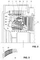
- reference number 1 is a rotor, with 2 a stator sheet metal body, with 3 its laminated press plate and with 4 denotes a housing surrounding the stator sheet metal body 2.
- the stator winding consists of a lower rod 5 and an upper rod 6, the ends of which protrude from the stator sheet metal body 2, the so-called end brackets, are electrically and mechanically connected to one another.
- the entirety of all front brackets forms the end winding.
- Line connectors 7 lead from the end brackets to ring lines 8 in the winding head space 9, which in the example is surrounded by its own winding head housing 10.
- This housing 10 is attached to the stator housing 4 in a gas-tight manner, e.g. screwed on.
- the stator housing 4 can, however, also be formed in one piece with the said end winding 10. For this reason, the machine housing is only spoken of in general below.
- the winding head is supported with a solid inner ring 11 made of glass fiber-reinforced synthetic resin, the outer surface of which is adapted to the widening end brackets, and two solid, one-piece outer rings 12 and 13 the same material.
- a wedge-shaped filler 14 made of insulating material is inserted between the lower rod 5 and upper rod 6.
- the two outer rings 12, 13 engage in recesses in an axially extending support beam 15. This is screwed to a mounting bracket 16, which in turn is attached to the stator press plate 3.
- the two outer rings 12, 13 must be installed before the stator winding is installed and cannot be removed without destruction, so that a different type of winding head support must be used when repairing the stator winding or similar work.
- the actual bracing and consolidation of the winding head is carried out by pressing the inner ring 11 into the conically tapering winding basket, which is formed by the upper bars 6, and then axially securing the inner ring 11.
- FIG. 1 clearly shows, there is very limited space in the winding head space 9 on the connection side (NS side). Even if the outer ring 12 could be pulled off axially via the end winding, at least the numerous line connectors 7 would have to be removed.
- FIGS. 2 and 3 the same or equivalent parts are provided with the same reference numbers as in FIG. 1.
- the inner ring 11 and the outer ring 12 are removed during a repair or as part of the retrofit.
- the mounting bracket 16 together with the support sheet 15 are unscrewed.
- These modified support beams 15a have a round recess radially on the outside for receiving a cord ring 17 and can also extend in the circumferential direction be adapted to the geometry of the cord ring 17.
- the surface of the modified support beam 15a facing the lower rod 5 runs approximately parallel to the lower rod 5 in the central section and merges into a wedge surface 18 in the edge region.
- the cord ring 15a consists of cords or fuses 23 which are continuously wound around the modified support beams 15a in many turns.
- Glass fiber cords are preferably used here, as have been used for years for fixing and spacing the conductors and coils of winding heads of electrical machines and are described, for example, in CH-A-425 983.
- Such cords have a core of glass fibers running in the longitudinal direction of the cord, which are surrounded by an elastic covering or braid. This wrapping can - but does not have to be removed after winding.
- Kevlar can also be used.
- the cords are either drawn in and wound up and then impregnated with a synthetic resin which is then cured, or the cords 23 are previously impregnated with a synthetic resin in the B state, which is cured under heat after winding.
- the impregnating resin preferably an epoxy resin
- the cord ring 17 can also be reinforced by a bandage of cords or fines 25 of the same structure (FIG. 3).
- the cord ring 17 is only slightly inferior to a solid ring made of glass fiber reinforced synthetic resin in terms of strength and elasticity. In contrast to a multi-part ring, it can also be attached where space is limited.
- the inner ring 11a is pressed in and axially secured in a suitable manner.
- the above-described support of the winding head with inner ring 11a and (outer) cord ring 17 and the double wedge arrangement 19, 20 prevents tensile forces on the radially inner portion of the stator press plate 2 and the stator sheet metal body 2. Without the cord ring 17 acts due to the radially acting clamping force P 1 and the leverage of the support beam 15a and mounting bracket 16a a tensile stress P2 on the stator lamination body. Such tensile forces lead to loosening of the sheet metal body and can damage the insulation of the stator winding in the area of the sheet metal body. The cord ring 17 prevents this leverage by absorbing the radial force P 1.
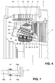
- the embodiment according to FIG. 4 essentially differs from that according to FIG. 3 in that a cord ring 25 also takes the place of a solid inner ring 11a.
- This has the same structure as the outer one Cord ring 17, thus consists of synthetic resin-impregnated rags or cords 23. These are wound up in a kind of gauge or shape outside the machine and, after being introduced into the interior of the winding head, using pressure and heat, they are pressed into a ring which is completely attached to the top rods 6 hugs.
- underlays 24 made of glass mat are provided between the inner cord ring 25 and the end brackets 6, which are bonded to both the inner cord ring 25 and the end brackets 6 during curing. After curing, the inner cord ring 25 can be additionally secured axially by bandages 26.
- the further assembly is carried out analogously to the procedure as described in connection with Fig.2.
- the outer cord ring 17 is applied.
- the winding head assembly consisting of the inner cord ring 25, end bracket and outer cord ring 17 is tensioned via the double wedge arrangement 19, 20 by means of the screw bolts 21.
- connection side (NS side) of large electrical machines
- cord technology offers the possibility of being able to optimally adapt the outer ring 17 to the existing space conditions, and therefore extremely complex disassembly and modification the ring connections and the derivatives are unnecessary.
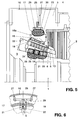
- the inner and / or the outer ring can also be designed as a cord ring. This is illustrated in Figure 5, for example.
- the inner ring is a cord ring 25, the outer also a cord ring 17.
- New to the designs shown in FIGS. 2 and 4 is the rigid radial support of the entire AS winding head relative to the housing 10, while the axial support is flexible is. The reason for this property is explained in more detail below.
- These two support functions take over radially inward struts 27 which are fastened to the winding head housing 10.
- Axially flexible azimuthally extending leaf springs 28 are fastened between these struts 27, to which a T-shaped support 29 is fastened in the central section, as can be seen from the top view according to FIG.
- the radially inner surface 30 of the supports 29 is curved in the circumferential direction as well as axially concave and serves as an abutment for the cord ring 17.
- the struts 27 can alternatively themselves be designed as leaf springs.
- the T-shaped supports 29 are attached directly to the struts (not shown). Both in the case shown and in the alternative mentioned, the fastening angles (position 16a in FIGS. 2 and 4) are omitted, and a gap S remains between the support beam 15a and the end face of the stator press plate 3.
- a further possibility of axially flexible external support of the winding head is to support it axially and not flexibly on the winding head housing 10, but on the stator press plate 3.
- the struts 27, leaf springs 28 and T-shaped supports 29 are omitted.
- support brackets 16a and support beams 15a are then to be provided, but the parts 15a and 16a mentioned are not fixed but with interposed axially acting spring elements, for example Spring washers or disc springs 31, as can be seen from the section according to FIG. 7, are connected to one another, which enable a relative movement between the winding head and the stator press plate 3.
- the cooling of the stator winding and the stator sheet metal body in the large electrical machines considered here is normally carried out with hydrogen or water.
- the coolant is supplied from the exciter side (LV side), flows through the winding rod through waveguides and exits again on the turbine side (LV side). This has the consequence that the expansion of the winding head on the excitation side and practically the first half of the active part changes little with respect to the sheet metal body.
- the greater thermal expansions relative to the sheet metal body occur primarily in the stator winding rod and in the winding end on the turbine side.
- the winding head support is axially flexible on the turbine side (exception for machines with a small iron length), on the other hand, a fixed winding head support can be used on the exciter side (connection side, NS side), as illustrated in FIGS. 2 and 4. If necessary, however, axially flexible support according to FIG. 7 can also be implemented there and with comparatively little effort.
Landscapes
- Engineering & Computer Science (AREA)
- Power Engineering (AREA)
- Insulation, Fastening Of Motor, Generator Windings (AREA)
Applications Claiming Priority (2)
| Application Number | Priority Date | Filing Date | Title |
|---|---|---|---|
| DE4302989A DE4302989A1 (de) | 1993-02-03 | 1993-02-03 | Vorrichtung zur Halterung der Windungsenden einer Statorwicklung in einer dynamoelektrischen Maschine |
| DE4302989 | 1993-02-03 |
Publications (2)
| Publication Number | Publication Date |
|---|---|
| EP0609679A1 true EP0609679A1 (fr) | 1994-08-10 |
| EP0609679B1 EP0609679B1 (fr) | 1996-08-28 |
Family
ID=6479511
Family Applications (1)
| Application Number | Title | Priority Date | Filing Date |
|---|---|---|---|
| EP94100474A Expired - Lifetime EP0609679B1 (fr) | 1993-02-03 | 1994-01-14 | Dispositif de support des spires terminales d'un enroulement statorique dans une machine dynamo-électrique |
Country Status (4)
| Country | Link |
|---|---|
| US (1) | US5436520A (fr) |
| EP (1) | EP0609679B1 (fr) |
| DE (2) | DE4302989A1 (fr) |
| ES (1) | ES2093455T3 (fr) |
Cited By (1)
| Publication number | Priority date | Publication date | Assignee | Title |
|---|---|---|---|---|
| WO1997006593A1 (fr) * | 1995-08-04 | 1997-02-20 | Siemens Aktiengesellschaft | Tete d'enroulement d'un enroulement de stator d'une machine electrique pourvue d'elements tendeurs |
Families Citing this family (16)
| Publication number | Priority date | Publication date | Assignee | Title |
|---|---|---|---|---|
| DE4424215A1 (de) * | 1994-07-09 | 1996-01-11 | Abb Management Ag | Vorrichtung zur Halterung der Stabenden einer Statorwicklung in einer dynamoelektrischen Maschine |
| US5705875A (en) * | 1994-08-01 | 1998-01-06 | Westinghouse Electric Corporation | Generator end winding system |
| JP3504352B2 (ja) * | 1994-10-05 | 2004-03-08 | 三菱電機株式会社 | 車両用交流発電機の回転子 |
| DE19755569A1 (de) * | 1997-12-15 | 1999-06-17 | Asea Brown Boveri | Elektrische Maschine mit einem verspannten Wickelkopf |
| US7096566B2 (en) * | 2001-01-09 | 2006-08-29 | Black & Decker Inc. | Method for making an encapsulated coil structure |
| US6946758B2 (en) | 2001-01-09 | 2005-09-20 | Black & Decker Inc. | Dynamoelectric machine having encapsulated coil structure with one or more of phase change additives, insert molded features and insulated pinion |
| CZ20031901A3 (cs) | 2001-01-09 | 2003-11-12 | Black & Decker Inc. | Elektrický motor s kotvou potaženou tepelně vodivým plastem |
| US7814641B2 (en) | 2001-01-09 | 2010-10-19 | Black & Decker Inc. | Method of forming a power tool |
| DE10310306A1 (de) * | 2002-03-12 | 2003-09-25 | Alstom Switzerland Ltd | Vorrichtung zum Spannen einer Statorwicklung |
| DE102007062078B3 (de) * | 2007-12-21 | 2009-01-15 | Sensoplan Aktiengesellschaft | Sanierverfahren für den Wickelkopf eines elektrischen Generators |
| US8461741B2 (en) * | 2010-10-14 | 2013-06-11 | General Electric Company | Low friction support system for dynamoelectric machine |
| US8461742B2 (en) * | 2010-11-19 | 2013-06-11 | General Electric Company | Support system for dynamoelectric machine |
| JP6585538B2 (ja) * | 2016-03-31 | 2019-10-02 | 株式会社東芝 | 回転電機の製造方法 |
| JP7094384B2 (ja) * | 2018-03-27 | 2022-07-01 | シーメンス エナジー インコーポレイテッド | 発電機ステータ端部巻線コイル支持アセンブリ |
| DE102019124206A1 (de) * | 2019-09-10 | 2021-03-11 | Audi Ag | Elektrische Maschine und Verfahren zum Aufbringen wenigstens einer Wicklung auf einen Wicklungsträger einer elektrischen Maschine |
| CN112688453A (zh) * | 2020-12-09 | 2021-04-20 | 诺丁汉(余姚)智能电气化研究院有限公司 | 一种端部绕组磁通电机 |
Citations (6)
| Publication number | Priority date | Publication date | Assignee | Title |
|---|---|---|---|---|
| US3435517A (en) * | 1963-09-23 | 1969-04-01 | Gen Electric | Method of making a tieless bracing of stator coil end turns |
| DE1538807A1 (de) * | 1965-07-28 | 1970-03-26 | Gen Electric | Windungsstuetzsystem einer dynamoelektrischen Maschine |
| DE1563039A1 (de) * | 1966-12-28 | 1970-06-11 | Siemens Ag | Verfahren zur Herstellung versteifter kurzschlussfester Wicklungen elektrischer Maschinen |
| US4016443A (en) * | 1975-05-22 | 1977-04-05 | Westinghouse Electric Corporation | Turbine generator end-winding support apparatus |
| DE2554839A1 (de) * | 1975-11-14 | 1977-05-26 | Bbc Brown Boveri & Cie | Verfahren zur abstuetzung und distanzierung der leiter und spulen im wickelkopf elektrischer maschinen |
| EP0432720A1 (fr) * | 1989-12-15 | 1991-06-19 | Klaus Dr. Ing. Weigelt | Tête de bobinage de stator, ensemble de rechange pour celle-ci et méthode pour son remplacement |
Family Cites Families (19)
| Publication number | Priority date | Publication date | Assignee | Title |
|---|---|---|---|---|
| DE35276C (de) * | Frau J. E. KUSENBERG in Altona, Steinstr. 65a | Saugflasche mit eingeschmolzener Saugröhre für Kinder | ||
| DE1015914B (de) * | 1953-09-03 | 1957-09-19 | Gen Electric | Befestigung der Wickelkoepfe dynamoelektrischer Maschinen |
| FR1366320A (fr) * | 1963-07-31 | 1964-07-10 | Cem Comp Electro Mec | Perfectionnement aux dispositifs de fixation des têtes de bobines des turboalternateurs de grande puissance |
| CH402146A (de) * | 1963-09-26 | 1965-11-15 | Bbc Brown Boveri & Cie | Abstützung für die Statorwickelköpfe von Turbogeneratoren |
| DE1197971B (de) * | 1963-10-04 | 1965-08-05 | Bbc Brown Boveri & Cie | Abstuetzung fuer die Statorwickelkoepfe von Turbogeneratoren |
| CH425983A (de) * | 1965-09-13 | 1966-12-15 | Bbc Brown Boveri & Cie | Verfahren zur Fixierung der Leiter und Spulen von Wickelköpfen elektrischer Maschinen und nach dem Verfahren hergestellte elektrische Maschine |
| US3436580A (en) * | 1966-10-14 | 1969-04-01 | Gen Electric | Stator end turn bracing system |
| DE7015282U (de) * | 1970-04-24 | 1970-07-23 | Siemens Ag | Wickelkopfbandage fuer elektrische maschinen. |
| US3665234A (en) * | 1970-12-14 | 1972-05-23 | Gen Electric | Generator end winding support |
| SU381132A1 (ru) * | 1971-06-17 | 1973-05-15 | Центральное Конструкторское Бюро Главэнергоремонта | Статор электрической машины |
| US4088913A (en) * | 1976-02-20 | 1978-05-09 | Prigorovsky Igor Alexandrovich | Electrical machine stator |
| US4238339A (en) * | 1978-11-27 | 1980-12-09 | Fridman Vladimir M | Arrangement for supporting stator end windings of an electric machine |
| SU807451A1 (ru) * | 1979-05-24 | 1981-02-23 | Предприятие П/Я А-7376 | Устройство дл креплени лобовыхчАСТЕй ОбМОТКи CTATOPA элЕКТРичЕС-КОй МАшиНы (ЕгО ВАРиАНТы) |
| US4501985A (en) * | 1984-05-01 | 1985-02-26 | Westinghouse Electric Corp. | Dynamoelectric machine with end turn support assembly having fasteners with locking devices |
| US4563607A (en) * | 1984-05-11 | 1986-01-07 | Westinghouse Electric Corp. | Radial clamp assembly for dynamoelectric machine stator coil end turns |
| US4800314A (en) * | 1987-08-24 | 1989-01-24 | Westinghouse Electric Corp. | Deep beam support arrangement for dynamoelectric machine stator coil end portions |
| SU1721720A1 (ru) * | 1988-12-12 | 1992-03-23 | Научно-Исследовательский, Проектно-Конструкторский И Технологический Институт Тяжелого Машиностроения Харьковского Завода "Электротяжмаш" Им.В.И.Ленина | Статор электрической машины |
| ES2053035T3 (es) * | 1989-09-20 | 1994-07-16 | Asea Brown Boveri | Dispositivo para la fijacion de extremos de devanado de un devanado de estator en una maquina dinamoelectrica. |
| DE4024395A1 (de) * | 1989-09-20 | 1991-03-28 | Asea Brown Boveri | Vorrichtung zur halterung der windungsenden einer statorwicklung in einer dynamoelektrischen maschine |
-
1993
- 1993-02-03 DE DE4302989A patent/DE4302989A1/de not_active Withdrawn
-
1994
- 1994-01-14 EP EP94100474A patent/EP0609679B1/fr not_active Expired - Lifetime
- 1994-01-14 ES ES94100474T patent/ES2093455T3/es not_active Expired - Lifetime
- 1994-01-14 DE DE59400527T patent/DE59400527D1/de not_active Expired - Fee Related
- 1994-01-18 US US08/209,742 patent/US5436520A/en not_active Expired - Fee Related
Patent Citations (6)
| Publication number | Priority date | Publication date | Assignee | Title |
|---|---|---|---|---|
| US3435517A (en) * | 1963-09-23 | 1969-04-01 | Gen Electric | Method of making a tieless bracing of stator coil end turns |
| DE1538807A1 (de) * | 1965-07-28 | 1970-03-26 | Gen Electric | Windungsstuetzsystem einer dynamoelektrischen Maschine |
| DE1563039A1 (de) * | 1966-12-28 | 1970-06-11 | Siemens Ag | Verfahren zur Herstellung versteifter kurzschlussfester Wicklungen elektrischer Maschinen |
| US4016443A (en) * | 1975-05-22 | 1977-04-05 | Westinghouse Electric Corporation | Turbine generator end-winding support apparatus |
| DE2554839A1 (de) * | 1975-11-14 | 1977-05-26 | Bbc Brown Boveri & Cie | Verfahren zur abstuetzung und distanzierung der leiter und spulen im wickelkopf elektrischer maschinen |
| EP0432720A1 (fr) * | 1989-12-15 | 1991-06-19 | Klaus Dr. Ing. Weigelt | Tête de bobinage de stator, ensemble de rechange pour celle-ci et méthode pour son remplacement |
Cited By (1)
| Publication number | Priority date | Publication date | Assignee | Title |
|---|---|---|---|---|
| WO1997006593A1 (fr) * | 1995-08-04 | 1997-02-20 | Siemens Aktiengesellschaft | Tete d'enroulement d'un enroulement de stator d'une machine electrique pourvue d'elements tendeurs |
Also Published As
| Publication number | Publication date |
|---|---|
| DE4302989A1 (de) | 1994-08-04 |
| US5436520A (en) | 1995-07-25 |
| EP0609679B1 (fr) | 1996-08-28 |
| ES2093455T3 (es) | 1996-12-16 |
| DE59400527D1 (de) | 1996-10-02 |
Similar Documents
| Publication | Publication Date | Title |
|---|---|---|
| EP0609679B1 (fr) | Dispositif de support des spires terminales d'un enroulement statorique dans une machine dynamo-électrique | |
| EP0432720B1 (fr) | Tête de bobinage de stator, ensemble de rechange pour celle-ci et méthode pour son remplacement | |
| EP0633644B1 (fr) | Dispositif de fixation des extrémités de bobinage d'un enroulement statorique dans une machine dynamoélectrique | |
| DE4406400A1 (de) | Vorrichtung zur Halterung der Windungsenden einer Statorwicklung in einer dynamoelektrischen Maschine | |
| EP0645871B1 (fr) | Connexion électrique et mécanique de sous-conducteurs pour l'arrivée et le départ du liquide de refroidissement | |
| EP0418530B1 (fr) | Dispositif de fixation des spires terminales d'un enroulement statorique dans une machine dynamo-électrique | |
| DE2600928A1 (de) | Befestigungs- und verspanneinrichtung fuer wicklungsleiter in elektrischen maschinen | |
| DE1200932B (de) | Wickelkopfhalterung fuer die Statorwicklung einer dynamoelektrischen Maschine | |
| EP0175075A1 (fr) | Machine électrique tournante | |
| DE102018210040A1 (de) | Anordnung und verfahren zum stützen von wickelkopfspulen eines generatorstators | |
| EP0691728B1 (fr) | Dispositif de support pour les têtes de bobines statoriques d'une machine dynamo-électrique | |
| DE102022205370A1 (de) | Reparaturverfahren für Statoreisenkern | |
| DE2620984C2 (de) | Elektrische Maschine mit Luftspaltwicklung | |
| EP2417694A1 (fr) | Machine dynamoélectrique | |
| DE69303866T2 (de) | Einrichtung zur elastischen Lagerung von Statorwickelköpfe | |
| EP0238933A2 (fr) | Support de tête de bobinage pour machines électriques | |
| DE10310306A1 (de) | Vorrichtung zum Spannen einer Statorwicklung | |
| DE4024395A1 (de) | Vorrichtung zur halterung der windungsenden einer statorwicklung in einer dynamoelektrischen maschine | |
| EP2146418B1 (fr) | Générateur électrique pour la production d'électricité dans des centrales et procédé d'assainissement | |
| CH682610A5 (de) | Rotor einer elektrischen Maschine mit einer Erregerstromzuleitung. | |
| DE1502645B2 (de) | Umfangsschleifscheibe | |
| EP2006979A2 (fr) | Procédé de fabrication d'un arbre de rotor pour générateurs électriques pour le gain d'énergie dans des centrales électriques | |
| DE19631768A1 (de) | Wickelkopf einer Statorwicklung einer elektrischen Maschine mit Spannelementen | |
| DE2703365A1 (de) | Anordnung zur befestigung von wickelkoepfen der statorwicklung einer elektrischen maschine | |
| DE1801104A1 (de) | Elektrische Maschine grossen Durchmessers mit vertikaler Welle |
Legal Events
| Date | Code | Title | Description |
|---|---|---|---|
| PUAI | Public reference made under article 153(3) epc to a published international application that has entered the european phase |
Free format text: ORIGINAL CODE: 0009012 |
|
| AK | Designated contracting states |
Kind code of ref document: A1 Designated state(s): BE CH DE ES FR IT LI |
|
| 17P | Request for examination filed |
Effective date: 19950121 |
|
| GRAG | Despatch of communication of intention to grant |
Free format text: ORIGINAL CODE: EPIDOS AGRA |
|
| GRAH | Despatch of communication of intention to grant a patent |
Free format text: ORIGINAL CODE: EPIDOS IGRA |
|
| 17Q | First examination report despatched |
Effective date: 19960209 |
|
| GRAH | Despatch of communication of intention to grant a patent |
Free format text: ORIGINAL CODE: EPIDOS IGRA |
|
| GRAA | (expected) grant |
Free format text: ORIGINAL CODE: 0009210 |
|
| AK | Designated contracting states |
Kind code of ref document: B1 Designated state(s): BE CH DE ES FR IT LI |
|
| REF | Corresponds to: |
Ref document number: 59400527 Country of ref document: DE Date of ref document: 19961002 |
|
| ITF | It: translation for a ep patent filed | ||
| ET | Fr: translation filed | ||
| PGFP | Annual fee paid to national office [announced via postgrant information from national office to epo] |
Ref country code: FR Payment date: 19961216 Year of fee payment: 4 |
|
| REG | Reference to a national code |
Ref country code: ES Ref legal event code: FG2A Ref document number: 2093455 Country of ref document: ES Kind code of ref document: T3 |
|
| PGFP | Annual fee paid to national office [announced via postgrant information from national office to epo] |
Ref country code: DE Payment date: 19970123 Year of fee payment: 4 |
|
| PGFP | Annual fee paid to national office [announced via postgrant information from national office to epo] |
Ref country code: ES Payment date: 19970129 Year of fee payment: 4 |
|
| PG25 | Lapsed in a contracting state [announced via postgrant information from national office to epo] |
Ref country code: LI Effective date: 19970131 Ref country code: CH Effective date: 19970131 Ref country code: BE Effective date: 19970131 |
|
| PLBE | No opposition filed within time limit |
Free format text: ORIGINAL CODE: 0009261 |
|
| STAA | Information on the status of an ep patent application or granted ep patent |
Free format text: STATUS: NO OPPOSITION FILED WITHIN TIME LIMIT |
|
| 26N | No opposition filed | ||
| REG | Reference to a national code |
Ref country code: CH Ref legal event code: PL |
|
| PG25 | Lapsed in a contracting state [announced via postgrant information from national office to epo] |
Ref country code: ES Free format text: LAPSE BECAUSE OF EXPIRATION OF PROTECTION Effective date: 19980115 |
|
| PG25 | Lapsed in a contracting state [announced via postgrant information from national office to epo] |
Ref country code: FR Free format text: THE PATENT HAS BEEN ANNULLED BY A DECISION OF A NATIONAL AUTHORITY Effective date: 19980131 |
|
| PG25 | Lapsed in a contracting state [announced via postgrant information from national office to epo] |
Ref country code: DE Free format text: LAPSE BECAUSE OF NON-PAYMENT OF DUE FEES Effective date: 19981001 |
|
| REG | Reference to a national code |
Ref country code: FR Ref legal event code: ST |
|
| REG | Reference to a national code |
Ref country code: ES Ref legal event code: FD2A Effective date: 20000601 |
|
| PG25 | Lapsed in a contracting state [announced via postgrant information from national office to epo] |
Ref country code: IT Free format text: LAPSE BECAUSE OF NON-PAYMENT OF DUE FEES;WARNING: LAPSES OF ITALIAN PATENTS WITH EFFECTIVE DATE BEFORE 2007 MAY HAVE OCCURRED AT ANY TIME BEFORE 2007. THE CORRECT EFFECTIVE DATE MAY BE DIFFERENT FROM THE ONE RECORDED. Effective date: 20050114 |