EP0609705A1 - Entraînement direct par moteur électrique - Google Patents
Entraînement direct par moteur électrique Download PDFInfo
- Publication number
- EP0609705A1 EP0609705A1 EP94100741A EP94100741A EP0609705A1 EP 0609705 A1 EP0609705 A1 EP 0609705A1 EP 94100741 A EP94100741 A EP 94100741A EP 94100741 A EP94100741 A EP 94100741A EP 0609705 A1 EP0609705 A1 EP 0609705A1
- Authority
- EP
- European Patent Office
- Prior art keywords
- direct drive
- drive according
- wheel
- external rotor
- stator core
- Prior art date
- Legal status (The legal status is an assumption and is not a legal conclusion. Google has not performed a legal analysis and makes no representation as to the accuracy of the status listed.)
- Granted
Links
- 230000001360 synchronised effect Effects 0.000 claims description 3
- 238000003475 lamination Methods 0.000 abstract 3
- 239000002184 metal Substances 0.000 abstract 2
- 230000005540 biological transmission Effects 0.000 description 4
- 238000007789 sealing Methods 0.000 description 1
Images

Classifications
-
- B—PERFORMING OPERATIONS; TRANSPORTING
- B60—VEHICLES IN GENERAL
- B60K—ARRANGEMENT OR MOUNTING OF PROPULSION UNITS OR OF TRANSMISSIONS IN VEHICLES; ARRANGEMENT OR MOUNTING OF PLURAL DIVERSE PRIME-MOVERS IN VEHICLES; AUXILIARY DRIVES FOR VEHICLES; INSTRUMENTATION OR DASHBOARDS FOR VEHICLES; ARRANGEMENTS IN CONNECTION WITH COOLING, AIR INTAKE, GAS EXHAUST OR FUEL SUPPLY OF PROPULSION UNITS IN VEHICLES
- B60K7/00—Disposition of motor in, or adjacent to, traction wheel
- B60K7/0007—Disposition of motor in, or adjacent to, traction wheel the motor being electric
-
- B—PERFORMING OPERATIONS; TRANSPORTING
- B60—VEHICLES IN GENERAL
- B60K—ARRANGEMENT OR MOUNTING OF PROPULSION UNITS OR OF TRANSMISSIONS IN VEHICLES; ARRANGEMENT OR MOUNTING OF PLURAL DIVERSE PRIME-MOVERS IN VEHICLES; AUXILIARY DRIVES FOR VEHICLES; INSTRUMENTATION OR DASHBOARDS FOR VEHICLES; ARRANGEMENTS IN CONNECTION WITH COOLING, AIR INTAKE, GAS EXHAUST OR FUEL SUPPLY OF PROPULSION UNITS IN VEHICLES
- B60K7/00—Disposition of motor in, or adjacent to, traction wheel
- B60K2007/0038—Disposition of motor in, or adjacent to, traction wheel the motor moving together with the wheel axle
-
- B—PERFORMING OPERATIONS; TRANSPORTING
- B60—VEHICLES IN GENERAL
- B60K—ARRANGEMENT OR MOUNTING OF PROPULSION UNITS OR OF TRANSMISSIONS IN VEHICLES; ARRANGEMENT OR MOUNTING OF PLURAL DIVERSE PRIME-MOVERS IN VEHICLES; AUXILIARY DRIVES FOR VEHICLES; INSTRUMENTATION OR DASHBOARDS FOR VEHICLES; ARRANGEMENTS IN CONNECTION WITH COOLING, AIR INTAKE, GAS EXHAUST OR FUEL SUPPLY OF PROPULSION UNITS IN VEHICLES
- B60K7/00—Disposition of motor in, or adjacent to, traction wheel
- B60K2007/0092—Disposition of motor in, or adjacent to, traction wheel the motor axle being coaxial to the wheel axle
Definitions
- the invention relates to an electromotive direct drive.
- EP-A-0 413 337 discloses an electromotive direct drive for rail vehicles, in which an electronically commutated, housing-free electric motor is arranged axially next to a vehicle wheel to be driven.
- the outer rotor of the electric motor is attached to the axle shaft of the vehicle wheel to be driven or directly to the vehicle wheel without the interposition of a transmission.
- the axle shaft of the vehicle wheel is rotatably mounted in the chassis at its two projecting ends.
- the individual vehicle wheel cannot be steered because the axle shaft cannot be pivoted horizontally relative to the chassis.
- the known direct drive is also axially relatively wide, so that the driven vehicle wheels require a correspondingly wide wheel arch. As a result, the passenger compartment in the area of these wheel arches is narrowed, particularly in the case of low-floor rail vehicles.
- DE-C-35 38 513 also describes an electromotive wheel hub drive for rail vehicles, in which the wheel carrier is formed by the stator housing part of the electric motor.
- the rotor shaft of the electric motor is rotatably mounted coaxially to the single wheel and is axially externally connected to the single wheel via a planetary gear.
- the wheel bearings of the individual wheel to be driven are additionally loaded by the weight of the electric motor and the brake disc. Because of its compactness, the known wheel hub drive requires only small wheel arches, so that a low floor of the wagon is used in low-floor rail vehicles can be realized.
- the wheel hub drive according to DE-C-35 38 513 which can also be used with steerable individual wheels, however requires sealing measures and regular oil changes because of its transmission.
- the object of the present invention is to create a compact, maintenance-friendly and structurally simple direct drive for steerable individual wheels.
- the direct drive according to the invention is designed as an external rotor motor which is arranged axially next to the driven individual wheel, which is mounted on an at least horizontally pivotable wheel carrier.
- the external rotor of the external rotor motor is direct, e.g. connected to the single wheel by means of bolts, whereas the stator core is held in such a manner that it cannot rotate, so that the pivoting movement of the wheel carrier is carried out by the latter.
- the external rotor is thus connected to the single wheel in a particularly simple manner without the interposition of a transmission and thus in a structurally simple manner.
- the direct connection of the outer rotor with the single wheel and the support-free, non-rotatable mounting of the stator core package outside the outer rotor ensures that the weight of the outer rotor motor is only transferred directly to the outer rotor and single wheel via the connection point. Because the weight of the external rotor motor is transferred directly to the rail via the driven single wheel, the wheel bearings are not additionally loaded by the weight of the external rotor motor. By relieving the wheel bearings is in advantageously reduces the wear of the parts in question.
- undercarriage in the embodiment according to claim 2 here not only includes undercarriage pillars and undercarriage swings or bogie swings, but also pick-up points in the vehicle body, e.g. in the car body or in the wheel arch.
- the brake disc In a direct drive according to claim 6, the brake disc always runs at the wheel speed in an advantageous manner. Compared to a brake disc, which runs at a higher speed than the wheel speed due to a gear ratio, significantly lower imbalances occur. In addition, the weight of the brake disc and the connecting element is transferred via the external rotor directly to the driven single wheel and from there directly to the rail. This means that the wheel bearings are not additionally loaded by the weight of the brake disc.
- An embodiment according to claim 4 in conjunction with claims 6 and 9 allows rail vehicles with a relatively small track width, e.g. 1 m to create a low-floor vehicle with a relatively large passage width in the area of the wheel arches. Despite the external fastening of the external rotor motor to the single wheel, such a direct drive is still arranged within the external vehicle contour.
- this can be designed either as an inverter-fed asynchronous motor (claim 10) or as a synchronous motor (claim 11).
- 1 denotes a single wheel of a rail vehicle.
- the single wheel 1 can be steered by its mounting on an at least horizontally pivotable wheel carrier 2.
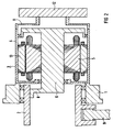
- An outer rotor motor 3 with an outer rotor 4 and a stator core 5 is arranged axially next to the steerable single wheel 1.
- the external rotor 4 is directly connected to the single wheel 1, that is to say without the interposition of a transmission.
- the stator core 5 is arranged in a rotationally fixed manner. In the exemplary embodiments shown in FIGS. 1 and 2, the stator core assembly 5 is seated on a carrier 6, which is secured against rotation on the chassis or on the vehicle (FIG. 1) or via a torque support 7 (FIG. 1) or a torque support 8 (FIG. 2) Wheel carrier (FIG 2) is attached.
- the stator core 5 is held in a rotationally fixed manner by the torque support 7 or 8, but can be pivoted together with the wheel carrier 2.
- the necessary movable support of the torque support 7 on the chassis or on the vehicle can be achieved, for example, by a ball joint, not shown in FIG.
- a bracket of the torque support 8 by means of a ball and socket joint is not required, since the torque support 8 is held in the wheel carrier 2.
- both the torque support 7 and the torque support 8 must be attached flexibly in order to avoid constraining forces.
- the horizontal pivoting of the wheel carrier 2 relative to the chassis or vehicle is caused by a bracket 9.
- the bracket 9 also allows the wheel carrier 2 and thus the individual wheel 1 with its external rotor motor 3 to be deflected vertically.
- a brake disc 12 is fastened to the external rotor 4 via a connecting element 10 (FIG. 1) or 11 (FIG. 2).
- the brake disc 12 thus advantageously always rotates at the wheel speed.
- the external rotor motor 3 is designed as an inverter-fed asynchronous motor, the external rotor 4 of which has a laminated rotor core 13;
- the external rotor motor 3 can also be designed as a synchronous motor, the external rotor of which has permanent magnets distributed in a ring.
- the two embodiments in FIGS. 1 and 2 differ in that in the direct drive according to FIG. 1 the brake disc 12 is arranged on the wheel carrier side on the outer rotor 4, whereas in the direct drive in FIG. 2 the brake disc 12 is arranged on the side facing away from the individual wheel 1.
- the torque support 7 or 8 is arranged on the side of the external rotor motor 3, which is opposite the brake disc 12.
- the individual wheel 1 is rotated by 180 ° in relation to the exemplary embodiment in accordance with FIG. In both cases, the brake disc 12 is therefore arranged on the outside of the vehicle.
- the direct drive according to FIG. 2 also allows rail vehicles with a relatively small track width, e.g. 1 m to create a low-floor vehicle with a relatively large passage width in the area of the wheel arches.
- the invention is not limited to rail vehicles; rather, the direct drive according to the invention is e.g. can also be used on road vehicles.
Landscapes
- Engineering & Computer Science (AREA)
- Chemical & Material Sciences (AREA)
- Combustion & Propulsion (AREA)
- Transportation (AREA)
- Mechanical Engineering (AREA)
- Arrangement Or Mounting Of Propulsion Units For Vehicles (AREA)
- Primary Cells (AREA)
- Toys (AREA)
- Management, Administration, Business Operations System, And Electronic Commerce (AREA)
- Replacing, Conveying, And Pick-Finding For Filamentary Materials (AREA)
- Braking Arrangements (AREA)
Applications Claiming Priority (2)
| Application Number | Priority Date | Filing Date | Title |
|---|---|---|---|
| DE4303069 | 1993-02-03 | ||
| DE4303069A DE4303069C1 (de) | 1993-02-03 | 1993-02-03 | Elektromotorischer Direktantrieb |
Publications (2)
| Publication Number | Publication Date |
|---|---|
| EP0609705A1 true EP0609705A1 (fr) | 1994-08-10 |
| EP0609705B1 EP0609705B1 (fr) | 1996-04-17 |
Family
ID=6479551
Family Applications (1)
| Application Number | Title | Priority Date | Filing Date |
|---|---|---|---|
| EP94100741A Expired - Lifetime EP0609705B1 (fr) | 1993-02-03 | 1994-01-19 | Entraînement direct par moteur électrique |
Country Status (4)
| Country | Link |
|---|---|
| EP (1) | EP0609705B1 (fr) |
| AT (1) | ATE136850T1 (fr) |
| DE (2) | DE4303069C1 (fr) |
| ES (1) | ES2086239T3 (fr) |
Cited By (5)
| Publication number | Priority date | Publication date | Assignee | Title |
|---|---|---|---|---|
| EP0699550A3 (fr) * | 1994-08-31 | 1996-04-17 | Gerhard Riepl | Propulsion électrique économisant l'énergie, pour petits véhicules |
| FR2742937A1 (fr) * | 1995-12-21 | 1997-06-27 | Jeumont Ind | Dispositif d'entrainement d'un vehicule |
| US7530415B2 (en) | 2000-01-26 | 2009-05-12 | E-Traction Europe B.V. | Wheel provided with driving means |
| US9233603B2 (en) | 2000-01-26 | 2016-01-12 | E-Traction Europe B.V. | Wheel provided with driving means |
| CZ306771B6 (cs) * | 2015-08-28 | 2017-06-28 | Ĺ KODA TRANSPORTATION a.s. | Pohon otočného podvozku, zejména pro nízkopodlažní kolejové vozidlo |
Families Citing this family (3)
| Publication number | Priority date | Publication date | Assignee | Title |
|---|---|---|---|---|
| AT505153B1 (de) * | 2007-06-15 | 2008-11-15 | Traktionssysteme Austria Gmbh | Schienenfahrzeug-direktantrieb sowie verfahren zu seiner herstellung |
| BE1019194A4 (nl) * | 2010-02-23 | 2012-04-03 | Willy D'hulst | Magneet mobiel. |
| ES3033345T3 (en) * | 2021-03-30 | 2025-08-01 | Traction Innovation B V | Inverted portal axle for use in a low floor bus |
Citations (4)
| Publication number | Priority date | Publication date | Assignee | Title |
|---|---|---|---|---|
| DE3817537A1 (de) * | 1988-05-24 | 1988-12-22 | Josef Klaus | Antrieb fuer ein fahrzeug |
| EP0337032A1 (fr) * | 1988-03-29 | 1989-10-18 | Nippon Steel Corporation | Véhicule électrique |
| EP0413337A1 (fr) * | 1989-08-18 | 1991-02-20 | Magnet-Motor Gesellschaft Für Magnetmotorische Technik Mbh | Véhicule ferroviaire avec moteur électrique à entraînement direct |
| EP0464929A2 (fr) * | 1990-07-03 | 1992-01-08 | ELETTROMECCANICA PARIZZI S.p.A | Ensemble de propulsion électrique disposé dans une roue pour bogies de véhicules ferroviaires et de tramways |
Family Cites Families (2)
| Publication number | Priority date | Publication date | Assignee | Title |
|---|---|---|---|---|
| DE3323686A1 (de) * | 1983-07-01 | 1985-01-03 | Fried. Krupp Gmbh, 4300 Essen | Schaufelradkopf |
| DE4111627C2 (de) * | 1991-04-10 | 1994-06-09 | Wolfgang Hill | Elektromotor für ein Elektromobil zum Einbau in eine Radfelge |
-
1993
- 1993-02-03 DE DE4303069A patent/DE4303069C1/de not_active Expired - Fee Related
-
1994
- 1994-01-19 AT AT94100741T patent/ATE136850T1/de not_active IP Right Cessation
- 1994-01-19 DE DE59400197T patent/DE59400197D1/de not_active Expired - Fee Related
- 1994-01-19 ES ES94100741T patent/ES2086239T3/es not_active Expired - Lifetime
- 1994-01-19 EP EP94100741A patent/EP0609705B1/fr not_active Expired - Lifetime
Patent Citations (4)
| Publication number | Priority date | Publication date | Assignee | Title |
|---|---|---|---|---|
| EP0337032A1 (fr) * | 1988-03-29 | 1989-10-18 | Nippon Steel Corporation | Véhicule électrique |
| DE3817537A1 (de) * | 1988-05-24 | 1988-12-22 | Josef Klaus | Antrieb fuer ein fahrzeug |
| EP0413337A1 (fr) * | 1989-08-18 | 1991-02-20 | Magnet-Motor Gesellschaft Für Magnetmotorische Technik Mbh | Véhicule ferroviaire avec moteur électrique à entraînement direct |
| EP0464929A2 (fr) * | 1990-07-03 | 1992-01-08 | ELETTROMECCANICA PARIZZI S.p.A | Ensemble de propulsion électrique disposé dans une roue pour bogies de véhicules ferroviaires et de tramways |
Cited By (7)
| Publication number | Priority date | Publication date | Assignee | Title |
|---|---|---|---|---|
| EP0699550A3 (fr) * | 1994-08-31 | 1996-04-17 | Gerhard Riepl | Propulsion électrique économisant l'énergie, pour petits véhicules |
| US5796192A (en) * | 1994-08-31 | 1998-08-18 | Riepl; Gerhard | Energy-saving electric drive for small vehicles |
| FR2742937A1 (fr) * | 1995-12-21 | 1997-06-27 | Jeumont Ind | Dispositif d'entrainement d'un vehicule |
| WO1997023942A1 (fr) * | 1995-12-21 | 1997-07-03 | Jeumot Industrie | Systeme d'entrainement en rotation d'un dispositif |
| US7530415B2 (en) | 2000-01-26 | 2009-05-12 | E-Traction Europe B.V. | Wheel provided with driving means |
| US9233603B2 (en) | 2000-01-26 | 2016-01-12 | E-Traction Europe B.V. | Wheel provided with driving means |
| CZ306771B6 (cs) * | 2015-08-28 | 2017-06-28 | Ĺ KODA TRANSPORTATION a.s. | Pohon otočného podvozku, zejména pro nízkopodlažní kolejové vozidlo |
Also Published As
| Publication number | Publication date |
|---|---|
| ES2086239T3 (es) | 1996-06-16 |
| DE4303069C1 (de) | 1994-03-17 |
| ATE136850T1 (de) | 1996-05-15 |
| EP0609705B1 (fr) | 1996-04-17 |
| DE59400197D1 (de) | 1996-05-23 |
Similar Documents
| Publication | Publication Date | Title |
|---|---|---|
| DE4234831C1 (de) | Antrieb für ein Fahrzeugrad | |
| DE10256596A1 (de) | Antriebssystem für ein Elektrofahrzeug | |
| EP0507137B1 (fr) | Train d'entraînement dirigeable | |
| EP1470013A1 (fr) | Essieu moteur a entrainement direct dote de deux moteurs d'entrainement | |
| EP1289790B1 (fr) | Essieu moteur entraine directement pourvu d'un etage de transmission planetaire-differentiel | |
| EP0579084B1 (fr) | Moteur de propulsion | |
| DE69405202T2 (de) | Untersetzungsgetriebe und Kraftübertragung mit zwei Gangstufen für ein Kraftfahrzeug | |
| EP0609705B1 (fr) | Entraînement direct par moteur électrique | |
| DE10160313A1 (de) | Überlagerungsgetriebe für eine Überlagerungslenkung | |
| DE68903095T2 (de) | Lenkvorrichtung fuer die hinterraeder eines durch vier raeder gelenkten fahrzeuges. | |
| AT408333B (de) | Fahrzeugrad | |
| EP1104378A1 (fr) | Direction assistee par moteur electrique, dotee d'un engrenage planetaire compact | |
| EP0542171A1 (fr) | Unité motorisée pour engins de traction ferroviaires | |
| DE102021213063A1 (de) | Lenkantrieb für eine Lenkachse eines lenkbaren Fahrzeugs, Lenkachse und Flurförderzeug | |
| DE102015217050A1 (de) | Nutzfahrzeuglenkung | |
| DE20213670U1 (de) | Direkt angetriebene Antriebsachse mit zwei Antriebsmotoren | |
| DE102022203955B4 (de) | Lenkbare Antriebseinheit für ein Flurförderzeug und Flurförderzeug | |
| DE102019127965A1 (de) | Lenkgetriebe für ein elektromechanisches lenksystem für ein fahrzeug und elektromechanisches lenksystem für ein fahrzeug | |
| EP0589865B1 (fr) | Assemblage de frein pour véhicules ferroviaires | |
| EP0626286B1 (fr) | Dispositif d'entrainement d'une seule roue | |
| DE102007038264A1 (de) | Aktiver Stabilisator zur Wankstabilisierung | |
| DE10142599A1 (de) | Lenksystem für Fahrzeuge | |
| DE10350862A1 (de) | Kraftübertragungssystem für ein elektrisches Fahrzeug | |
| DE4105780A1 (de) | Servolenkung fuer ein kraftfahrzeug | |
| DE102007055766A1 (de) | Antriebseinheit für elektromotorisch angetriebene Fahrzeuge, insbesondere für Flurförderzeuge |
Legal Events
| Date | Code | Title | Description |
|---|---|---|---|
| PUAI | Public reference made under article 153(3) epc to a published international application that has entered the european phase |
Free format text: ORIGINAL CODE: 0009012 |
|
| AK | Designated contracting states |
Kind code of ref document: A1 Designated state(s): AT BE CH DE ES FR LI NL SE |
|
| 17P | Request for examination filed |
Effective date: 19941018 |
|
| 17Q | First examination report despatched |
Effective date: 19941111 |
|
| GRAH | Despatch of communication of intention to grant a patent |
Free format text: ORIGINAL CODE: EPIDOS IGRA |
|
| GRAA | (expected) grant |
Free format text: ORIGINAL CODE: 0009210 |
|
| AK | Designated contracting states |
Kind code of ref document: B1 Designated state(s): AT BE CH DE ES FR LI NL SE |
|
| PG25 | Lapsed in a contracting state [announced via postgrant information from national office to epo] |
Ref country code: NL Free format text: LAPSE BECAUSE OF FAILURE TO SUBMIT A TRANSLATION OF THE DESCRIPTION OR TO PAY THE FEE WITHIN THE PRESCRIBED TIME-LIMIT Effective date: 19960417 Ref country code: BE Effective date: 19960417 |
|
| REF | Corresponds to: |
Ref document number: 136850 Country of ref document: AT Date of ref document: 19960515 Kind code of ref document: T |
|
| REG | Reference to a national code |
Ref country code: CH Ref legal event code: NV Representative=s name: SIEMENS SCHWEIZ AG |
|
| REF | Corresponds to: |
Ref document number: 59400197 Country of ref document: DE Date of ref document: 19960523 |
|
| REG | Reference to a national code |
Ref country code: ES Ref legal event code: FG2A Ref document number: 2086239 Country of ref document: ES Kind code of ref document: T3 |
|
| ET | Fr: translation filed | ||
| NLV1 | Nl: lapsed or annulled due to failure to fulfill the requirements of art. 29p and 29m of the patents act | ||
| PGFP | Annual fee paid to national office [announced via postgrant information from national office to epo] |
Ref country code: AT Payment date: 19970113 Year of fee payment: 4 |
|
| PGFP | Annual fee paid to national office [announced via postgrant information from national office to epo] |
Ref country code: SE Payment date: 19970117 Year of fee payment: 4 Ref country code: ES Payment date: 19970117 Year of fee payment: 4 |
|
| PGFP | Annual fee paid to national office [announced via postgrant information from national office to epo] |
Ref country code: FR Payment date: 19970123 Year of fee payment: 4 |
|
| PG25 | Lapsed in a contracting state [announced via postgrant information from national office to epo] |
Ref country code: LI Effective date: 19970131 Ref country code: CH Effective date: 19970131 |
|
| PLBE | No opposition filed within time limit |
Free format text: ORIGINAL CODE: 0009261 |
|
| STAA | Information on the status of an ep patent application or granted ep patent |
Free format text: STATUS: NO OPPOSITION FILED WITHIN TIME LIMIT |
|
| PGFP | Annual fee paid to national office [announced via postgrant information from national office to epo] |
Ref country code: DE Payment date: 19970317 Year of fee payment: 4 |
|
| 26N | No opposition filed | ||
| REG | Reference to a national code |
Ref country code: CH Ref legal event code: PL |
|
| PG25 | Lapsed in a contracting state [announced via postgrant information from national office to epo] |
Ref country code: AT Free format text: LAPSE BECAUSE OF NON-PAYMENT OF DUE FEES Effective date: 19980119 |
|
| PG25 | Lapsed in a contracting state [announced via postgrant information from national office to epo] |
Ref country code: SE Free format text: LAPSE BECAUSE OF NON-PAYMENT OF DUE FEES Effective date: 19980120 Ref country code: ES Free format text: LAPSE BECAUSE OF EXPIRATION OF PROTECTION Effective date: 19980120 |
|
| PG25 | Lapsed in a contracting state [announced via postgrant information from national office to epo] |
Ref country code: FR Free format text: THE PATENT HAS BEEN ANNULLED BY A DECISION OF A NATIONAL AUTHORITY Effective date: 19980131 |
|
| PG25 | Lapsed in a contracting state [announced via postgrant information from national office to epo] |
Ref country code: DE Free format text: LAPSE BECAUSE OF NON-PAYMENT OF DUE FEES Effective date: 19981001 |
|
| EUG | Se: european patent has lapsed |
Ref document number: 94100741.1 |
|
| REG | Reference to a national code |
Ref country code: FR Ref legal event code: ST |
|
| REG | Reference to a national code |
Ref country code: ES Ref legal event code: FD2A Effective date: 20000601 |