EP0609720B1 - Ventil mit Stellhebelanschlag - Google Patents
Ventil mit Stellhebelanschlag Download PDFInfo
- Publication number
- EP0609720B1 EP0609720B1 EP94100853A EP94100853A EP0609720B1 EP 0609720 B1 EP0609720 B1 EP 0609720B1 EP 94100853 A EP94100853 A EP 94100853A EP 94100853 A EP94100853 A EP 94100853A EP 0609720 B1 EP0609720 B1 EP 0609720B1
- Authority
- EP
- European Patent Office
- Prior art keywords
- wedge
- valve
- sleeve
- wedge element
- adjusting lever
- Prior art date
- Legal status (The legal status is an assumption and is not a legal conclusion. Google has not performed a legal analysis and makes no representation as to the accuracy of the status listed.)
- Expired - Lifetime
Links
- 238000001746 injection moulding Methods 0.000 claims description 2
- 229920003023 plastic Polymers 0.000 claims description 2
- 239000004033 plastic Substances 0.000 claims description 2
- 238000010276 construction Methods 0.000 claims 1
- 230000000694 effects Effects 0.000 claims 1
- 230000000717 retained effect Effects 0.000 claims 1
- 238000009420 retrofitting Methods 0.000 abstract 1
- XLYOFNOQVPJJNP-UHFFFAOYSA-N water Substances O XLYOFNOQVPJJNP-UHFFFAOYSA-N 0.000 description 5
- 238000009434 installation Methods 0.000 description 1
- 239000000463 material Substances 0.000 description 1
- 230000007704 transition Effects 0.000 description 1
Images
Classifications
-
- F—MECHANICAL ENGINEERING; LIGHTING; HEATING; WEAPONS; BLASTING
- F16—ENGINEERING ELEMENTS AND UNITS; GENERAL MEASURES FOR PRODUCING AND MAINTAINING EFFECTIVE FUNCTIONING OF MACHINES OR INSTALLATIONS; THERMAL INSULATION IN GENERAL
- F16K—VALVES; TAPS; COCKS; ACTUATING-FLOATS; DEVICES FOR VENTING OR AERATING
- F16K31/00—Actuating devices; Operating means; Releasing devices
- F16K31/44—Mechanical actuating means
- F16K31/60—Handles
- F16K31/605—Handles for single handle mixing valves
Definitions
- the invention relates to a valve with the features specified in the preamble of claim 1.
- a valve is known from GB-A-2 110 240.
- a stop sleeve which has stop stages arranged on the end face, is arranged on a toothed part of an actuating lever.
- EP-A-0 568 013 there is also shown a valve in which a bushing is provided on an actuating lever, on which a plurality of projections for swiveling limitation are formed on one end face.
- a valve is known in which a set screw is provided in the adjusting lever in a transverse threaded bore.
- the grub screw can be turned radially out of the adjusting lever so that the projecting end face of the grub screw interacts with the stop surface formed on the valve housing.
- the invention has for its object to provide a flow limiting device in a valve according to the preamble of claim 1, which can also be used retrospectively on the valve and which can be manufactured inexpensively.
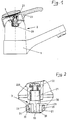
- a valve 1 is shown in part for arrangement on a washstand, etc. Through connection pipes, not shown in the drawing, the fitting 1 is supplied with cold water and hot water from the supply line network.
- a valve 2 is provided in the valve 1, the individual valve elements of which are encapsulated in a valve housing 20.
- An adjusting lever 21 made of square material is axially guided out of the valve housing 20, to which a handle 22 is fastened with the interposition of an insulating bushing 220.
- the handle 22 is movable in two degrees of freedom. By turning the handle 22 about the vertical axis, the mixing ratio of the incoming cold and hot water, with a pivoting about the horizontal axis, the water flow rate of the valve 2 can be adjusted.
- fixed stops 23 are formed on the valve housing 20, against which the actuating lever 21 rests in the maximum open position or the closed position of the valve 2, as can be seen in particular from FIG. 2 of the drawing.
- a wedge element 3 can be arranged between the actuating lever 21 and the fixed stop 23 .
- the wedge element 3 is integrally formed on a sleeve 30 which comprises the adjusting lever 21.
- the sleeve 30 with the wedge element 3 is axially supported on the one hand with side cheeks 33 in the region of the horizontal pivot axis on the housing 20 and on the other hand is secured in the plug-in position by the handle 22 with the insulating bushing 220.
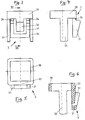
- the wedge element 3, as can be seen in particular from FIGS. 3 to 6, is formed in one piece with the sleeve 30 and the side cheeks 33 and is made of plastic by injection molding.
- the wedge element 3 consists of a higher wedge 31, which is guided as a U-shaped bracket around a flatter wedge (32), as can be seen in particular from FIGS. 3 and 6.
- the U-shaped bracket of the higher wedge 31 is provided in the region of the transition to the sleeve 30 with predetermined breaking points 34 designed as grooves, so that the higher bracket 31 can optionally be broken off.
- the wedge element can be installed in the following way: In the case of an already installed fitting 1, the handle 22 with the insulating bush 220 is first removed from the actuating lever 21 of the valve 2. Now the wedge element 3 with the sleeve 30 can be slid over the adjusting lever 21 until the side cheeks 33 come into contact with the valve housing 20. The handle 22 can then be fastened again to the actuating lever 21 with the insulating bushing 220. According to this, the maximum flow limitation is effective or the wedge element 3 prevents the originally possible maximum opening of the valve 2 with the wedge 31.
- the wedge element 3 can be removed again the wedge 31 is broken off at the predetermined breaking points 34 and then the wedge element 3 is reinstalled, so that in this version the flow restriction is reduced or the maximum flow rate is increased.
- three different maximum flow positions of the actuating lever 21 can be determined, namely, a relatively strong throttling with the wedge 31, a lower throttling with the wedge 32 and no throttling at all without the wedge element 3.
- the wedge element 3 can of course also be installed in the factory when the valve 1 is fully assembled, in addition to the subsequent installation in already installed valves.
- the sleeve 30 is not slotted, so that it can only be pushed axially onto the adjusting lever 21.
- the sleeve can also be slotted on the end face facing away from the wedge element 3, so that it can also be snapped onto the adjusting lever 21 laterally.
Landscapes
- Engineering & Computer Science (AREA)
- General Engineering & Computer Science (AREA)
- Mechanical Engineering (AREA)
- Preventing Unauthorised Actuation Of Valves (AREA)
- Mechanically-Actuated Valves (AREA)
- Vehicle Body Suspensions (AREA)
- Body Structure For Vehicles (AREA)
- Pens And Brushes (AREA)
Applications Claiming Priority (2)
| Application Number | Priority Date | Filing Date | Title |
|---|---|---|---|
| DE4303191 | 1993-02-04 | ||
| DE4303191A DE4303191A1 (de) | 1993-02-04 | 1993-02-04 | Ventil mit Stellhebelanschlag |
Publications (2)
| Publication Number | Publication Date |
|---|---|
| EP0609720A1 EP0609720A1 (de) | 1994-08-10 |
| EP0609720B1 true EP0609720B1 (de) | 1997-10-01 |
Family
ID=6479632
Family Applications (1)
| Application Number | Title | Priority Date | Filing Date |
|---|---|---|---|
| EP94100853A Expired - Lifetime EP0609720B1 (de) | 1993-02-04 | 1994-01-21 | Ventil mit Stellhebelanschlag |
Country Status (5)
| Country | Link |
|---|---|
| EP (1) | EP0609720B1 (da) |
| AT (1) | ATE158848T1 (da) |
| DE (2) | DE4303191A1 (da) |
| DK (1) | DK0609720T3 (da) |
| ES (2) | ES2110129T3 (da) |
Cited By (2)
| Publication number | Priority date | Publication date | Assignee | Title |
|---|---|---|---|---|
| DE102009008564A1 (de) | 2009-02-12 | 2010-08-19 | Grohe Ag | Sanitärarmatur |
| DE102011115390A1 (de) | 2011-10-10 | 2013-04-11 | Grohe Ag | Durchflussrateneinstellvorrichtung für eine Sanitärarmatur |
Families Citing this family (2)
| Publication number | Priority date | Publication date | Assignee | Title |
|---|---|---|---|---|
| IT1281653B1 (it) * | 1995-11-03 | 1998-02-20 | Galatron Srl | Dispositivo limitatore di portata per valvole miscelatrici di acqua calda e fredda |
| DE102005020990B4 (de) * | 2005-05-03 | 2012-07-12 | Grohe Ag | Ventil mit einsetzbarer Durchflussmengenbegrenzung |
Family Cites Families (6)
| Publication number | Priority date | Publication date | Assignee | Title |
|---|---|---|---|---|
| CH654638A5 (de) * | 1981-11-26 | 1986-02-28 | Karrer Weber & Cie Ag | Sanitaere einhebel-mischbatterie. |
| DE3211619C2 (de) * | 1982-03-30 | 1986-12-04 | Heinrich Schulte & Sohn Gmbh & Co Kg, 5860 Iserlohn | Einhebel-Mischbatterie |
| DE3244121A1 (de) * | 1982-11-29 | 1984-05-30 | Friedrich Grohe Armaturenfabrik Gmbh & Co, 5870 Hemer | Sanitaermischventil |
| DE3426480A1 (de) * | 1984-07-18 | 1986-01-30 | Grohe Armaturen Friedrich | Sicherheitsmischventil |
| BE1003580A3 (fr) * | 1989-10-31 | 1992-04-28 | Staar Sa | Dispositif de reglage de debit pour robinet. |
| IT1260746B (it) * | 1992-04-30 | 1996-04-22 | Orlando Bosio | Dispositivo limitatore della portata in cartuccia miscelatrice monocomando per acqua calda e fredda |
-
1993
- 1993-02-04 DE DE4303191A patent/DE4303191A1/de not_active Withdrawn
-
1994
- 1994-01-21 DK DK94100853.4T patent/DK0609720T3/da active
- 1994-01-21 DE DE59404179T patent/DE59404179D1/de not_active Expired - Fee Related
- 1994-01-21 AT AT94100853T patent/ATE158848T1/de not_active IP Right Cessation
- 1994-01-21 ES ES94100853T patent/ES2110129T3/es not_active Expired - Lifetime
- 1994-01-21 EP EP94100853A patent/EP0609720B1/de not_active Expired - Lifetime
- 1994-01-31 ES ES09400242U patent/ES1026964Y/es not_active Expired - Lifetime
Cited By (4)
| Publication number | Priority date | Publication date | Assignee | Title |
|---|---|---|---|---|
| DE102009008564A1 (de) | 2009-02-12 | 2010-08-19 | Grohe Ag | Sanitärarmatur |
| DE102009008564B4 (de) * | 2009-02-12 | 2011-03-10 | Grohe Ag | Sanitärarmatur |
| DE102011115390A1 (de) | 2011-10-10 | 2013-04-11 | Grohe Ag | Durchflussrateneinstellvorrichtung für eine Sanitärarmatur |
| DE102011115390B4 (de) | 2011-10-10 | 2019-02-14 | Grohe Ag | Durchflussrateneinstellvorrichtung für eine Sanitärarmatur |
Also Published As
| Publication number | Publication date |
|---|---|
| ES1026964U (es) | 1994-06-16 |
| ES1026964Y (es) | 1995-02-16 |
| EP0609720A1 (de) | 1994-08-10 |
| DE4303191A1 (de) | 1994-08-11 |
| DE59404179D1 (de) | 1997-11-06 |
| DK0609720T3 (da) | 1998-04-14 |
| ATE158848T1 (de) | 1997-10-15 |
| ES2110129T3 (es) | 1998-02-01 |
Similar Documents
| Publication | Publication Date | Title |
|---|---|---|
| EP0662577B1 (de) | Betätigungseinrichtung für ein Einhebelmischventil | |
| EP0646688B1 (de) | Aussengriffanordnung für eine Tür, insbesondere eine Kraftfahrzeugtür | |
| EP1817466A2 (de) | Sanitärer wasserauslauf mit verschwenkbarer strömungsführung | |
| DE3612988A1 (de) | Mischbatterie | |
| DE3613854C1 (de) | Schaltvorrichtung | |
| EP1193432B1 (de) | Ventil, insbesondere Heizkörperventil | |
| EP0609720B1 (de) | Ventil mit Stellhebelanschlag | |
| EP1239496B1 (de) | Schaltscharnier | |
| EP0137154B1 (de) | Mehrwege-Hahn | |
| DE3428286C2 (da) | ||
| DE2944520A1 (de) | Ventiloberteil | |
| DE4407373A1 (de) | Voreinstellbares Regulierventil | |
| DE3041816C2 (da) | ||
| DE102005001303A1 (de) | Sanitäres Verteilerventil | |
| DE102006012304B4 (de) | Hebelventil | |
| EP0932175B1 (de) | Radiusbetätiger für Sicherheitsschalter | |
| DE3426480C2 (da) | ||
| EP0100468A2 (de) | Drehzapfenlager für Türen, insbesondere für Pendeltüren | |
| EP0787880A1 (de) | Höhenverstelleinrichtung für einen unteren Abschluss von Türen oder Fenstern | |
| DE3535176C2 (da) | ||
| DE29510071U1 (de) | Radiusbetätiger für Sicherheitsschalter | |
| DE3219574A1 (de) | Einhebelmischarmatur | |
| DE9312826U1 (de) | Wasserarmatur | |
| DE3034619A1 (de) | Ecklager fuer dreh-kipp-fenster, -tueren o.dgl. | |
| DE3416092C2 (da) |
Legal Events
| Date | Code | Title | Description |
|---|---|---|---|
| PUAI | Public reference made under article 153(3) epc to a published international application that has entered the european phase |
Free format text: ORIGINAL CODE: 0009012 |
|
| AK | Designated contracting states |
Kind code of ref document: A1 Designated state(s): AT CH DE DK ES FR GB IT LI SE |
|
| 17P | Request for examination filed |
Effective date: 19940824 |
|
| 17Q | First examination report despatched |
Effective date: 19951006 |
|
| GRAG | Despatch of communication of intention to grant |
Free format text: ORIGINAL CODE: EPIDOS AGRA |
|
| GRAH | Despatch of communication of intention to grant a patent |
Free format text: ORIGINAL CODE: EPIDOS IGRA |
|
| GRAH | Despatch of communication of intention to grant a patent |
Free format text: ORIGINAL CODE: EPIDOS IGRA |
|
| GRAA | (expected) grant |
Free format text: ORIGINAL CODE: 0009210 |
|
| AK | Designated contracting states |
Kind code of ref document: B1 Designated state(s): AT CH DE DK ES FR GB IT LI SE |
|
| REF | Corresponds to: |
Ref document number: 158848 Country of ref document: AT Date of ref document: 19971015 Kind code of ref document: T |
|
| REG | Reference to a national code |
Ref country code: CH Ref legal event code: EP |
|
| REF | Corresponds to: |
Ref document number: 59404179 Country of ref document: DE Date of ref document: 19971106 |
|
| ET | Fr: translation filed | ||
| REG | Reference to a national code |
Ref country code: CH Ref legal event code: NV Representative=s name: BOVARD AG PATENTANWAELTE |
|
| ITF | It: translation for a ep patent filed | ||
| GBT | Gb: translation of ep patent filed (gb section 77(6)(a)/1977) |
Effective date: 19971219 |
|
| REG | Reference to a national code |
Ref country code: ES Ref legal event code: FG2A Ref document number: 2110129 Country of ref document: ES Kind code of ref document: T3 |
|
| REG | Reference to a national code |
Ref country code: DK Ref legal event code: T3 |
|
| PLBE | No opposition filed within time limit |
Free format text: ORIGINAL CODE: 0009261 |
|
| STAA | Information on the status of an ep patent application or granted ep patent |
Free format text: STATUS: NO OPPOSITION FILED WITHIN TIME LIMIT |
|
| 26N | No opposition filed | ||
| PGFP | Annual fee paid to national office [announced via postgrant information from national office to epo] |
Ref country code: SE Payment date: 19981221 Year of fee payment: 6 |
|
| PGFP | Annual fee paid to national office [announced via postgrant information from national office to epo] |
Ref country code: FR Payment date: 19981230 Year of fee payment: 6 |
|
| PGFP | Annual fee paid to national office [announced via postgrant information from national office to epo] |
Ref country code: DK Payment date: 19990115 Year of fee payment: 6 |
|
| PGFP | Annual fee paid to national office [announced via postgrant information from national office to epo] |
Ref country code: CH Payment date: 19990118 Year of fee payment: 6 |
|
| PGFP | Annual fee paid to national office [announced via postgrant information from national office to epo] |
Ref country code: GB Payment date: 19990121 Year of fee payment: 6 |
|
| PGFP | Annual fee paid to national office [announced via postgrant information from national office to epo] |
Ref country code: AT Payment date: 19990126 Year of fee payment: 6 |
|
| PGFP | Annual fee paid to national office [announced via postgrant information from national office to epo] |
Ref country code: ES Payment date: 19990129 Year of fee payment: 6 |
|
| PG25 | Lapsed in a contracting state [announced via postgrant information from national office to epo] |
Ref country code: GB Free format text: LAPSE BECAUSE OF NON-PAYMENT OF DUE FEES Effective date: 20000121 Ref country code: DK Free format text: LAPSE BECAUSE OF NON-PAYMENT OF DUE FEES Effective date: 20000121 Ref country code: AT Free format text: LAPSE BECAUSE OF NON-PAYMENT OF DUE FEES Effective date: 20000121 |
|
| PG25 | Lapsed in a contracting state [announced via postgrant information from national office to epo] |
Ref country code: SE Free format text: LAPSE BECAUSE OF NON-PAYMENT OF DUE FEES Effective date: 20000122 Ref country code: ES Free format text: LAPSE BECAUSE OF NON-PAYMENT OF DUE FEES Effective date: 20000122 |
|
| PG25 | Lapsed in a contracting state [announced via postgrant information from national office to epo] |
Ref country code: LI Free format text: LAPSE BECAUSE OF NON-PAYMENT OF DUE FEES Effective date: 20000131 Ref country code: CH Free format text: LAPSE BECAUSE OF NON-PAYMENT OF DUE FEES Effective date: 20000131 |
|
| EUG | Se: european patent has lapsed |
Ref document number: 94100853.4 |
|
| GBPC | Gb: european patent ceased through non-payment of renewal fee |
Effective date: 20000121 |
|
| REG | Reference to a national code |
Ref country code: CH Ref legal event code: PL |
|
| PG25 | Lapsed in a contracting state [announced via postgrant information from national office to epo] |
Ref country code: FR Free format text: LAPSE BECAUSE OF NON-PAYMENT OF DUE FEES Effective date: 20000929 |
|
| REG | Reference to a national code |
Ref country code: DK Ref legal event code: EBP |
|
| REG | Reference to a national code |
Ref country code: FR Ref legal event code: ST |
|
| PGFP | Annual fee paid to national office [announced via postgrant information from national office to epo] |
Ref country code: DE Payment date: 20010123 Year of fee payment: 8 |
|
| REG | Reference to a national code |
Ref country code: ES Ref legal event code: FD2A Effective date: 20010910 |
|
| PG25 | Lapsed in a contracting state [announced via postgrant information from national office to epo] |
Ref country code: DE Free format text: LAPSE BECAUSE OF NON-PAYMENT OF DUE FEES Effective date: 20020801 |
|
| PG25 | Lapsed in a contracting state [announced via postgrant information from national office to epo] |
Ref country code: IT Free format text: LAPSE BECAUSE OF NON-PAYMENT OF DUE FEES;WARNING: LAPSES OF ITALIAN PATENTS WITH EFFECTIVE DATE BEFORE 2007 MAY HAVE OCCURRED AT ANY TIME BEFORE 2007. THE CORRECT EFFECTIVE DATE MAY BE DIFFERENT FROM THE ONE RECORDED. Effective date: 20050121 |