EP0609744A1 - Combiné pour appareil téléphonique à cordon - Google Patents
Combiné pour appareil téléphonique à cordon Download PDFInfo
- Publication number
- EP0609744A1 EP0609744A1 EP94100969A EP94100969A EP0609744A1 EP 0609744 A1 EP0609744 A1 EP 0609744A1 EP 94100969 A EP94100969 A EP 94100969A EP 94100969 A EP94100969 A EP 94100969A EP 0609744 A1 EP0609744 A1 EP 0609744A1
- Authority
- EP
- European Patent Office
- Prior art keywords
- handset
- carrier part
- earpiece
- socket
- capsule
- Prior art date
- Legal status (The legal status is an assumption and is not a legal conclusion. Google has not performed a legal analysis and makes no representation as to the accuracy of the status listed.)
- Withdrawn
Links
- 239000002775 capsule Substances 0.000 claims abstract description 27
- 239000004020 conductor Substances 0.000 claims abstract description 13
- 239000002184 metal Substances 0.000 claims abstract 2
- 239000004033 plastic Substances 0.000 claims description 10
- 238000004519 manufacturing process Methods 0.000 claims description 4
- 239000012777 electrically insulating material Substances 0.000 claims 1
- 239000007787 solid Substances 0.000 claims 1
- 239000012815 thermoplastic material Substances 0.000 claims 1
- 229910000679 solder Inorganic materials 0.000 abstract description 3
- 238000005476 soldering Methods 0.000 description 7
- 239000003990 capacitor Substances 0.000 description 3
- 238000006073 displacement reaction Methods 0.000 description 3
- 238000001746 injection moulding Methods 0.000 description 3
- 238000009413 insulation Methods 0.000 description 3
- 239000000463 material Substances 0.000 description 3
- 238000010276 construction Methods 0.000 description 2
- 238000000034 method Methods 0.000 description 2
- 229920000642 polymer Polymers 0.000 description 2
- 238000007789 sealing Methods 0.000 description 2
- 229920001169 thermoplastic Polymers 0.000 description 2
- 239000004416 thermosoftening plastic Substances 0.000 description 2
- 229920001342 Bakelite® Polymers 0.000 description 1
- 229910000906 Bronze Inorganic materials 0.000 description 1
- 229920001875 Ebonite Polymers 0.000 description 1
- 238000004026 adhesive bonding Methods 0.000 description 1
- 239000004637 bakelite Substances 0.000 description 1
- 230000005540 biological transmission Effects 0.000 description 1
- 239000010974 bronze Substances 0.000 description 1
- 239000000969 carrier Substances 0.000 description 1
- 239000000919 ceramic Substances 0.000 description 1
- 238000000748 compression moulding Methods 0.000 description 1
- KUNSUQLRTQLHQQ-UHFFFAOYSA-N copper tin Chemical compound [Cu].[Sn] KUNSUQLRTQLHQQ-UHFFFAOYSA-N 0.000 description 1
- 230000001419 dependent effect Effects 0.000 description 1
- 229920001971 elastomer Polymers 0.000 description 1
- 238000010292 electrical insulation Methods 0.000 description 1
- 238000007765 extrusion coating Methods 0.000 description 1
- 238000002347 injection Methods 0.000 description 1
- 239000007924 injection Substances 0.000 description 1
- 239000012778 molding material Substances 0.000 description 1
- 239000012811 non-conductive material Substances 0.000 description 1
- 238000004080 punching Methods 0.000 description 1
- 238000004064 recycling Methods 0.000 description 1
- 239000000243 solution Substances 0.000 description 1
- 230000008719 thickening Effects 0.000 description 1
- 239000002699 waste material Substances 0.000 description 1
- 238000003466 welding Methods 0.000 description 1
Images


Classifications
-
- H—ELECTRICITY
- H04—ELECTRIC COMMUNICATION TECHNIQUE
- H04M—TELEPHONIC COMMUNICATION
- H04M1/00—Substation equipment, e.g. for use by subscribers
- H04M1/02—Constructional features of telephone sets
- H04M1/03—Constructional features of telephone transmitters or receivers, e.g. telephone hand-sets
Definitions
- the invention relates to the handset of a corded telephone set according to the preamble of claim 1. It also relates to a method for producing such a handset.
- Corded telephones consisting of a base unit, a handset and an apparatus cord, are well known.
- a handset is known in particular which has two housing shells which, when assembled, together form a unit which is closed on all sides and into which electroacoustic transducers in the form of an earphone and a speech capsule are inserted.
- an earpiece is shown, for example, in the document CH 649 184. It is an independent unit that is inserted into the handset during assembly is electrically connected to the socket.
- a speech capsule is known from the document DE 29 39 479, which is constructed as an electret directional microphone. This capsule has a cylindrical housing with two electrical connections and forms a very handy unit.
- hearing and speaking capsules are intended to be coupled with acoustic resonance rooms in order to improve the acoustic properties of the "overall telephone system".
- So-called Helmholtz resonators are preferably used.
- the earphone 17 is essentially cylindrical except for the holding surfaces 115. It has an annular sealing lip and a flange-like contact surface. When the earpiece 17 is inserted into the lower housing shell 14, the sealing lip first snaps into an annular elevation 114. The flange-like contact surface finally lies on the end face of the elevation. In this way, there is only a very small resonance volume between the earpiece 17 and the sound outlet openings 19 of the housing shell 14.
- a socket 21 which is open to the outside and has a plurality of contact poles 25 which serve to receive a plug (not shown) of the apparatus cord.
- a carrier part 22 which carries this speech capsule and which is described in more detail below.
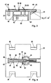
- FIG. 3 shows the carrier part 22 in a sectional side view, FIG. 4 in a top view, each enlarged by a factor of 2 compared to the natural dimensions.
- the carrier part 22 is a plastic injection molded part with considerable weight. It carries the speech capsule 18 in a guide and furthermore a capacitor 20. These elements are by means of their connecting wires with solder eyes 45, 46 and 47, 48 of two electrical leads 42, 43 soldered. For this purpose, these supply lines 42, 43 lie essentially flat on the surface of the carrier part 22 in such a way that the soldering eyes 45-48 are each aligned with an associated through opening of the carrier part 22. In this way, the connection wires mentioned can be brought into the soldering position without any problems.
- Two further supply lines 41, 44 are arranged parallel to the supply lines 42, 43 mentioned, but only partially lie flat on the surface of the carrier part 22. With their one ends, the further leads 41, 44 form obliquely bent solder lugs 51, 52 with crescent-shaped soldering hooks 53, 54. All leads 41-44 also have free, resilient ends 41'-44 'which are arranged parallel next to one another and which are U-shaped Surface of the support member 22 are bent and which form the poles 25 of the socket 21. To improve the contact properties, the contact surfaces of the ends 41'-44 'are tempered, e.g. gold-plated.
- the conductors 41-44 are preferably stamped and bent from spring bronze in a single stamping operation, webs, not shown, initially holding the various conductors 41-44 together.
- the conductors are then pressed as a single part into assigned grooves on the surface of the carrier part 22, where they are clamped in the grooves by means of a plurality of holding prongs 49, 50 and are thus essentially held firmly on the surface of the carrier part 22.
- the webs mentioned are finally punched out, for which purpose further through openings are provided in the carrier part 22 at the locations of these webs, through which the punching waste can fall out.
- the carrier part 22 has four holding points 24, at which snap hooks 16 of the lower device shell 14 engage and thus fix the carrier part 22 rigidly and shockproof in this device shell (FIG. 2).
- the speech capsule 18 is on its speech-sensitive side by a plastic Plastic part 61 covered, wherein a tubular connecting channel 62 makes acoustic contact with a resonance chamber 63.
- the plastic plastic part 61 is placed on the assembled and soldered speech capsule 18 and, when the handset 11 is fully assembled, tightly encloses the sound inlet opening 12 of the lower housing shell 14 (FIG. 1).
- the resonance chamber 63 is shaped in such a way that a double Helmholtz resonator results, which is used to shape the required transmission frequency response.
- the aforementioned weight of the carrier part 22 is necessary in order to give the handset 11 the weight which it must have in order to actuate the so-called hook switch in the base device of the telephone set. This weight thus also comes about without any additional component and is therefore inexpensive. It is also important that the carrier part 22 in the handset 11 distributes the weight together with the apparatus cord so that the handset 11 lies comfortably and ergonomically in the hand of the user.
- FIG. 5 shows the hearing capsule 17 on a likewise enlarged scale and in a half-open top view.
- This capsule comprises two wires 27, 28, the length of which corresponds approximately to the distance between the hearing capsule 17 and the carrier part 22 in the handset 11.
- the wires 27, 28 are essentially rigid, non-insulated lines with any, for example round Cross-section.
- they At the point of their passage through the wall 30 of the earphone, they have slight, sharp-edged thickenings 31, for example caused by crushing, with the aid of which they are rigidly clamped in the associated wall holes in the earphone 17.
- the line ends 27 ', 28' serve as carriers for the very thin electrical coil connections 32 of the electroacoustic transducer. These connections are produced in such a way that the coil connections 32 are placed tightly over the line ends 27 ', 28' and soldered, and that the line ends 27 ', 28' are then bent slightly towards the coil 33, as a result of which the coil connections 32 are sufficient Get game for the movement of the coil 33.
- the handset 11 is assembled as described below:
- the carrier part 22 forms a pre-assembly unit which consists of the actual carrier, the feed lines 41-44 used and the inserted and soldered speech capsule 18, the plastic part 61 placed on the speech capsule 18 and the capacitor 20.
- This preassembly unit is inserted into the lower housing shell 14 and is fixed in a self-acting manner by the snap hooks 16 at the four holding points 24.
- the earpiece 17 together with the wires 27, 28 likewise forms a single unit which can be inserted into the lower housing shell 14 under slight pressure and is fixed by means of the holding surfaces 115 and the snap holders 15 mentioned.
- the wires 27, 28 extend to the carrier part 22. They can now be hooked into the soldering hooks 53, 54 of the soldering lugs 51, 52 and then soldered to them.
- the upper housing shell 13 is placed on the lower shell 14 and snapped together at several edge points. This creates a significantly torsion-resistant unit. Finally, the plug of the apparatus cord is inserted into the socket 21.
- the parts and measures described result in a handset 11, the construction of which requires significantly fewer individual parts than all previous, known handsets. This has a decisive impact on the production costs, while the quality requirements with regard to electrical safety, acoustic quality, usability and service life are rather increased compared to what is known so far. There is also a Technical construction that is flexible and adaptable with regard to the aesthetic shape of the handset. In particular, a very flat design of the handset 11 is possible.
Landscapes
- Engineering & Computer Science (AREA)
- Signal Processing (AREA)
- Telephone Set Structure (AREA)
Applications Claiming Priority (2)
| Application Number | Priority Date | Filing Date | Title |
|---|---|---|---|
| CH312/93 | 1993-02-03 | ||
| CH31293 | 1993-02-03 |
Publications (1)
| Publication Number | Publication Date |
|---|---|
| EP0609744A1 true EP0609744A1 (fr) | 1994-08-10 |
Family
ID=4184139
Family Applications (1)
| Application Number | Title | Priority Date | Filing Date |
|---|---|---|---|
| EP94100969A Withdrawn EP0609744A1 (fr) | 1993-02-03 | 1994-01-24 | Combiné pour appareil téléphonique à cordon |
Country Status (1)
| Country | Link |
|---|---|
| EP (1) | EP0609744A1 (fr) |
Cited By (5)
| Publication number | Priority date | Publication date | Assignee | Title |
|---|---|---|---|---|
| DE19605297A1 (de) * | 1996-02-14 | 1997-08-21 | Swoboda Gmbh Geb | Telefonendgerät und Steckerbuchse für ein Telefonendgerät |
| EP0840396A1 (fr) * | 1996-11-04 | 1998-05-06 | Molex Incorporated | Connecteur électrique pour combiné téléphonique |
| WO1998051122A1 (fr) * | 1997-05-08 | 1998-11-12 | Ericsson Inc. | Microphone a pavillon a affaiblisseur resonateur de helmholtz |
| DE19816769A1 (de) * | 1998-04-16 | 1999-10-21 | Deutsche Telephonwerk Kabel | Fernsprechhandapparat |
| US6307934B1 (en) | 1999-06-03 | 2001-10-23 | Telefonaktiebolaget Lm Ericsson (Publ) | Multiconnector for mobile telephones |
Citations (5)
| Publication number | Priority date | Publication date | Assignee | Title |
|---|---|---|---|---|
| US4636591A (en) * | 1985-01-22 | 1987-01-13 | Northern Telecom Limited | Integral transmitter and modular jack assembly for a telephone set |
| US4712236A (en) * | 1986-05-01 | 1987-12-08 | AT&T Information Systems Inc. American Telephone & Telegraph Company | Telephone handset construction |
| US4803724A (en) * | 1986-02-28 | 1989-02-07 | Kabushiki Kaisha Toshiba | Hand set |
| DE8902176U1 (de) * | 1989-02-23 | 1989-04-13 | Siemens AG, 1000 Berlin und 8000 München | Halterung eines Mikrofons |
| DE3737623A1 (de) * | 1987-11-05 | 1989-05-18 | Siemens Ag | Befestigung von elektroakustischen wandlern innerhalb eines handapparates fuer fernsprechgeraete |
-
1994
- 1994-01-24 EP EP94100969A patent/EP0609744A1/fr not_active Withdrawn
Patent Citations (5)
| Publication number | Priority date | Publication date | Assignee | Title |
|---|---|---|---|---|
| US4636591A (en) * | 1985-01-22 | 1987-01-13 | Northern Telecom Limited | Integral transmitter and modular jack assembly for a telephone set |
| US4803724A (en) * | 1986-02-28 | 1989-02-07 | Kabushiki Kaisha Toshiba | Hand set |
| US4712236A (en) * | 1986-05-01 | 1987-12-08 | AT&T Information Systems Inc. American Telephone & Telegraph Company | Telephone handset construction |
| DE3737623A1 (de) * | 1987-11-05 | 1989-05-18 | Siemens Ag | Befestigung von elektroakustischen wandlern innerhalb eines handapparates fuer fernsprechgeraete |
| DE8902176U1 (de) * | 1989-02-23 | 1989-04-13 | Siemens AG, 1000 Berlin und 8000 München | Halterung eines Mikrofons |
Cited By (5)
| Publication number | Priority date | Publication date | Assignee | Title |
|---|---|---|---|---|
| DE19605297A1 (de) * | 1996-02-14 | 1997-08-21 | Swoboda Gmbh Geb | Telefonendgerät und Steckerbuchse für ein Telefonendgerät |
| EP0840396A1 (fr) * | 1996-11-04 | 1998-05-06 | Molex Incorporated | Connecteur électrique pour combiné téléphonique |
| WO1998051122A1 (fr) * | 1997-05-08 | 1998-11-12 | Ericsson Inc. | Microphone a pavillon a affaiblisseur resonateur de helmholtz |
| DE19816769A1 (de) * | 1998-04-16 | 1999-10-21 | Deutsche Telephonwerk Kabel | Fernsprechhandapparat |
| US6307934B1 (en) | 1999-06-03 | 2001-10-23 | Telefonaktiebolaget Lm Ericsson (Publ) | Multiconnector for mobile telephones |
Similar Documents
| Publication | Publication Date | Title |
|---|---|---|
| DE2120838C3 (de) | Elektrischer Steckverbinder | |
| EP1183909B1 (fr) | Prothese auditive retro-auriculaire | |
| DE69626285T2 (de) | Elektrischer Verbinder für Telefonhandapparat | |
| DE69106432T2 (de) | Piezoelektrischer Wandler. | |
| DE1762983B1 (de) | Vorrichtung zum mechanischen haltern und elektrischen an schluss einer hoerer oder mikrophonkapsel in einem fern sprechgeraet und verfahren zu ihrer herstellung | |
| DE112018004007T5 (de) | Mikro-planarlautsprecher | |
| EP1183907B1 (fr) | Appareil auditif se placant derriere l'oreille | |
| DE2603606A1 (de) | Elektrische subminiatur-anschlussanordnung | |
| DE2053142B2 (de) | Hauptrahmenverbinder | |
| DE102005047479A1 (de) | Aufbau zum Verbinden eines Drahtes mit einer Elementaufnahmeeinheit | |
| DE2951396A1 (de) | Anschlussvorrichtung fuer einen wandler | |
| DE2531841C3 (de) | Elektrischer Schnappschalter | |
| AT403334B (de) | Kontaktierung eines elektroakustischen wandlers | |
| DE19721497A1 (de) | Modulares Gehäusesystem | |
| EP0567850B1 (fr) | Connexion d'un haut-parleur et d'un circuit imprimé situés tous deux dans un poste téléphonique | |
| DE4121311C1 (fr) | ||
| DE2800471A1 (de) | Trichterlautsprecher | |
| EP0888652B1 (fr) | Element de couplage electrique | |
| CH668154A5 (en) | Hearing aid with electroacoustic transducer - fits behind ear and has facility for plugging in range of operational mode elements | |
| EP3419312B1 (fr) | Appareil auditif | |
| EP1414272B1 (fr) | Prothèse auditive avec un composant électronique externe | |
| EP0022544B1 (fr) | Transducteur électrodynamique, en particulier pour appareils téléphoniques | |
| DE19928241B4 (de) | Lautsprecher | |
| DE29622708U1 (de) | Kontaktierung eines elektroakustischen Wandlers | |
| DE19521124C1 (de) | Anschlußelelement für Lautsprecher-Boxen |
Legal Events
| Date | Code | Title | Description |
|---|---|---|---|
| PUAI | Public reference made under article 153(3) epc to a published international application that has entered the european phase |
Free format text: ORIGINAL CODE: 0009012 |
|
| AK | Designated contracting states |
Kind code of ref document: A1 Designated state(s): CH DE FR GB IT LI |
|
| 17P | Request for examination filed |
Effective date: 19950109 |
|
| STAA | Information on the status of an ep patent application or granted ep patent |
Free format text: STATUS: THE APPLICATION IS DEEMED TO BE WITHDRAWN |
|
| 18D | Application deemed to be withdrawn |
Effective date: 20000701 |