EP0609819A1 - Maus und Verfahren zur gleichzeitigen Steuerung von Cursorstelle und Verschiebung - Google Patents
Maus und Verfahren zur gleichzeitigen Steuerung von Cursorstelle und Verschiebung Download PDFInfo
- Publication number
- EP0609819A1 EP0609819A1 EP94101430A EP94101430A EP0609819A1 EP 0609819 A1 EP0609819 A1 EP 0609819A1 EP 94101430 A EP94101430 A EP 94101430A EP 94101430 A EP94101430 A EP 94101430A EP 0609819 A1 EP0609819 A1 EP 0609819A1
- Authority
- EP
- European Patent Office
- Prior art keywords
- scrolling
- mouse
- cursor
- computer
- supplementary control
- Prior art date
- Legal status (The legal status is an assumption and is not a legal conclusion. Google has not performed a legal analysis and makes no representation as to the accuracy of the status listed.)
- Withdrawn
Links
Images









Classifications
-
- G—PHYSICS
- G06—COMPUTING OR CALCULATING; COUNTING
- G06F—ELECTRIC DIGITAL DATA PROCESSING
- G06F3/00—Input arrangements for transferring data to be processed into a form capable of being handled by the computer; Output arrangements for transferring data from processing unit to output unit, e.g. interface arrangements
- G06F3/01—Input arrangements or combined input and output arrangements for interaction between user and computer
- G06F3/03—Arrangements for converting the position or the displacement of a member into a coded form
- G06F3/033—Pointing devices displaced or positioned by the user, e.g. mice, trackballs, pens or joysticks; Accessories therefor
- G06F3/038—Control and interface arrangements therefor, e.g. drivers or device-embedded control circuitry
-
- G—PHYSICS
- G06—COMPUTING OR CALCULATING; COUNTING
- G06F—ELECTRIC DIGITAL DATA PROCESSING
- G06F3/00—Input arrangements for transferring data to be processed into a form capable of being handled by the computer; Output arrangements for transferring data from processing unit to output unit, e.g. interface arrangements
- G06F3/01—Input arrangements or combined input and output arrangements for interaction between user and computer
- G06F3/03—Arrangements for converting the position or the displacement of a member into a coded form
- G06F3/0304—Detection arrangements using opto-electronic means
- G06F3/0312—Detection arrangements using opto-electronic means for tracking the rotation of a spherical or circular member, e.g. optical rotary encoders used in mice or trackballs using a tracking ball or in mouse scroll wheels
-
- G—PHYSICS
- G06—COMPUTING OR CALCULATING; COUNTING
- G06F—ELECTRIC DIGITAL DATA PROCESSING
- G06F3/00—Input arrangements for transferring data to be processed into a form capable of being handled by the computer; Output arrangements for transferring data from processing unit to output unit, e.g. interface arrangements
- G06F3/01—Input arrangements or combined input and output arrangements for interaction between user and computer
- G06F3/03—Arrangements for converting the position or the displacement of a member into a coded form
- G06F3/033—Pointing devices displaced or positioned by the user, e.g. mice, trackballs, pens or joysticks; Accessories therefor
- G06F3/0354—Pointing devices displaced or positioned by the user, e.g. mice, trackballs, pens or joysticks; Accessories therefor with detection of two-dimensional [2D] relative movements between the device, or an operating part thereof, and a plane or surface, e.g. 2D mice, trackballs, pens or pucks
- G06F3/03543—Mice or pucks
-
- G—PHYSICS
- G06—COMPUTING OR CALCULATING; COUNTING
- G06F—ELECTRIC DIGITAL DATA PROCESSING
- G06F3/00—Input arrangements for transferring data to be processed into a form capable of being handled by the computer; Output arrangements for transferring data from processing unit to output unit, e.g. interface arrangements
- G06F3/01—Input arrangements or combined input and output arrangements for interaction between user and computer
- G06F3/048—Interaction techniques based on graphical user interfaces [GUI]
- G06F3/0484—Interaction techniques based on graphical user interfaces [GUI] for the control of specific functions or operations, e.g. selecting or manipulating an object, an image or a displayed text element, setting a parameter value or selecting a range
- G06F3/0485—Scrolling or panning
Definitions
- the present invention relates to computer input devices in which a transducer converts translational motion of a housing into a position signal for controlling movement of a cursor or marker on a computer display system. More particularly, the present invention relates to an input device capable of generating additional control signals and an associated method to improve and speed-up its operation.
- a mouse as it has come to be known in the lexicography of the prior art, is a widespread computer input device, which has become greatly accepted among personal computer users and computer terminal users.
- a mechanical mouse consists essentially of a housing which can be slid by a single hand over a flat surface to generate a pair of signals in response to the relative motion of the housing over the flat surface.
- These signals are produced by a transducer typically located on the bottom or belly of the housing and are transmitted to computer means via communication means (e.g., a flexible cable connected to a computer's input port).
- the pair of signals represent orthogonal incremental motion components of the mouse in the x and y directions over the flat surface, in a suitable scale.
- the mouse movement is visually fed back to the user by a graphic symbol or cursor displayed on the computer screen that copies the movement of the mouse over a working surface or pad.
- the application program derives user commands according to spatial relationships between the displayed information and the cursor position on the screen when a switch is activated (usually in the form a push-button or similar means) provided on the back of the mouse for generating binary (i.e., on-off) control information.
- a three-dimensional mouse which produces three different signals representing orthogonal incremental position components in the x, y and z directions for use e.g., in positioning an object in a three-dimensional isometric display on a computer display means, is described in U.S. Patent 5,132,672 issued to Clark, July 21, 1992 and also in U.S. Patent 5,095,302 issued to McLean March 10, 1992.
- These devices operate producing signals for positions in the x and y directions in the same manner as in the conventional two-dimensional mouse and by producing the signal for the z direction by a transducer connected with a digit operable moveable component, such as a roller-belt or pressure sensitive button.
- the mouse's capability to generate position signals plus one or more binary control signals with just one hand of the user has turned it into a most useful tool for interactive computer program control. Its flexibility when used in combination with graphic user interfaces made this instrument a very popular input device, mostly for personal computer applications.
- a squeezable mouse is known that is structured to issue scrolling commands to an interactively operated program.
- binary switches are closed sending a binary command to the computer.
- This is equivalent to providing a mouse with a third button on its back, for sending an additional binary command, but using a different mouse handling technique.
- mice and methods for scrolling information displayed by a computer display means are based on positioning or moving a cursor within pre-determined areas of the display means, and issuing binary control commands, i.e., operating push-buttons or similar binary control means, while the cursor is positioned or moved within the boundaries or across the boundaries of those pre-determined areas.
- binary control commands i.e., operating push-buttons or similar binary control means
- scrolling operations generally need to be performed in a gradual way, scanning the data space in incremental steps through successive approximations so as to keep track of the displayed information until the desired data field is reached.
- This requires an appropriate apparatus and an operating method capable of providing a tight scrolling control, to allow fast scrolling direction switching and a wide range of available scrolling velocities.
- mice are conceived to drive a cursor over a finite workspace bounded by the screen limits, and are equipped with devices for generating only either movement commands or binary control commands.
- the mouse having means for scrolling as well as cursor positioning includes a supplementary control means for generating a supplementary signal from which scrolling commands are derived, when the supplementary signal is input to a computer.
- the supplementary control means includes a displaceable element movable by a digit of the same hand that holds and moves the mouse.
- the displaceable element has a bounded range of displacement amounts and is moved against a restoring force of a spring means from an equilibrium position in which no signal is generated, so as to produce a signal representing the amount of displacement of the displaceable element from its equilibrium position.
- the supplementary control means comprises a slidable knob, urged to a released or equilibrium position by a suitable restoring force provided by a spring-loaded mechanism, and mechanically engaged with a supplementary transducer for generating the supplementary control signal indicative of the knob displacement in an appropriate scale.
- the supplementary control signal is encoded, bundled with other mouse generated signals and transmitted to the computer using similar techniques and means as in conventional mice.
- the supplementary control signal is then processed and combined with the x-y mouse signals to control scrolling through a method that comprises detection of the dominant axis present in the cursor trail and further generation of incremental scrolling commands along the selected axis, at a rate determined by the amount of knob displacement from the equilibrium position. In this way, scrolling is always performed in the direction of the last cursor movement, which reflects the user's intention right before the scrolling operation begins.
- the cursor trail is analyzed in search of pre-defined patterns or gestures, which are used as general user-commands to set scrolling parameters.
- the scrolling parameters that can be dynamically changed are the scrolling axis (i.e., the scrolling direction) and the scrolling scale (i.e., the scrolling distance associated with each incremental scrolling command issued to the computer).
- the pre-defined patterns used are a vertical cursor motion, a horizontal cursor motion and a circular cursor motion.
- the vertical and horizontal patterns are used to set the scrolling axis as in the basic method, while the circular pattern is used to change the scrolling scale within a certain number of scrolling scale options.
- the vertical and horizontal patterns can be combined with the circular pattern to make scrolling axis and scrolling scale setting in a single continuous mouse movement.
- the associated method of the invention takes advantage of the information available in the cursor trail to allow concurrent control of scrolling and pointing, since scrolling commands can be issued from an arbitrary cursor position and at the same time the cursor position is controlled.
- a double-mode operability is provided by splitting the displacement range of the displaceable element (i.e., the knob) into two zones in which different scrolling modes are provided.
- One of the scrolling modes generates one single scrolling command to provide step-by-step scrolling, while the other mode generates a continuous train of scrolling commands to provide gradual scrolling at variable rates under user control.
- the main advantage of the mouse and method according to the invention is that it allows a user to concurrently and accurately control scrolling of the data space the cursor is pointing at, thus extending the mouse functionality to control not only the cursor position but the whole navigation process over a certain data space.
- the scrolling control device is part of the mouse system and it is inherently capable of generating bursts of scrolling commands of unlimited length without any mouse movement and regardless of its current position on the screen, the average x-y sliding distance of the mouse can be significantly reduced by eliminating repetitive trips to screen areas assigned to scrolling control (e.g., scroll bars). This leads to significant time savings and hence to greater mouse productivity and user comfort.
- the mouse according to the invention is comparatively inexpensive, since it only requires a comparatively few extra parts compared to those of the conventional prior art mouse.
- the associated operational method provides an additional degree of freedom to the mouse, but with no added hardware cost. This allows concurrent scrolling control in both horizontal and vertical directions and at different scrolling scales using only a single one-dimensional supplementary control means for that purpose.
- Fig. 1a, 1b and 1c show a mouse 10 according to the present invention, being this particular embodiment derived from a conventional mouse structure widely used in the industry, which is based on a rolling-sphere motion transducer 12.
- Mouse 10 comprises a housing 19 and a printed circuit board 23 supporting the electronic components of the mouse and the x-y transducer 12 as well.
- mouse 10 also comprises a supplementary control means 40, which in the preferred embodiment is also mounted on circuit board 23 as shown in figs. 1a and 1b.
- the displaceable element comprises a sliding knob 41, displaceable along a linear path provided by a pair of rails 77 and 79, which are part of the structure of the supplementary control means 40.
- Knob 41 is shaped preferably to an approximately cylindrical surface 45, so as to alter as little as possible the contour of the mouse housing 19, while providing a safe handling and a tight control of the knob position. The details of the supplementary control means structure are explained later on herein.
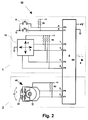
- FIG. 2 is a block diagram of the electronic circuit of mouse 10, according to the invention.
- Figure 2 shows a conventional mouse system delimited by block 1, including an x-y transducer assembly 12, responsive to movement of mouse 10 over a plane surface of a pad 28.
- Transducer assembly 12 may be of a mechanical type, like the one disclosed in U.S. Patent 3,541,541 (reference made herein above), or of the electro-optical type, like the one disclosed in U.S. Patents 4,364,035 and 4,546,347 both to Kirsch.
- any device capable of tracking the mouse x-y movement is suitable as transducer 12.
- transducer 12 generates a set of two pairs of signals X1-X2 and Y1-Y2, each one representing signed x-y incremental components of the mouse movement along orthogonal axis.
- Generic resistors R2 bias outputs X1, X2, Y1, Y2 from transducer 12. These outputs are synchronous quadrature pulse-signals as the ones generated by many mouse transducer devices used in the industry.
- both pairs of X and Y signals are read by parallel inputs P2 through P5 of a logic circuit means 4, which processes the signals to detect mouse motion and generates an output signal SO on an appropriate lead 5.
- Signal SO contains the x-y motion information which is transmitted to the computer.
- Figure 2 also shows two binary keys 6 biased via generic resistors R1. Keys 6 generate binary signals A and B for inputs P0 and P1 of logic circuit 4, which encodes them together with the x-y position signals, transmitting a composite signal to the computer for further processing.
- output 5 has been represented as consisting of a single conductor, signal S0 may be conveyed in either parallel or serial format, via either conductor means 36, or otherwise wireless means such as radio link or infrared radiation.
- mouse 10 may include more than two.
- the keys can be mechanical switches, but they may also be capacitive switches, conductive rubber switches or any other type of suitable binary switches.
- mouse 10 further includes a supplementary control means 40 for scrolling control, shown in block 2 of fig. 2.
- supplementary control means 40 generates a third pair of signals S1 and S2, in the same format as the X1, X2, Y1 and Y2 signals.
- Signals S1 and S2 are generated in response to a displacement of knob 41 from its equilibrium position, towards any displaced position.
- Signal outputs S1 and S2 are respectively connected to inputs P6 and P7 of logic circuit means 4, and are processed in the same way as the group of conventional signals X1, X2, Y1, Y2.
- the logic circuit means 4 can be a microcomputer configured with at least one 8-bit parallel input port and a serial output port (or a parallel output port capable of emulating a serial port), such as Motorola's MC146805 integrated circuit or the like.
- the x-y motion signals X1, X2, Y1, Y2, the scrolling control signals S1 and S2 and binary signals A and B are connected to P0 through P7 inputs of a parallel port of the microcomputer, to be read and processed as described above.
- the signal issued by output 5 is in a serial format and made into data packets using a technique described by John C. Hall in U.S. Patent 4,866,602.
- the mouse logic circuit means whenever there is any change of state of the mouse, the mouse logic circuit means generates a packet of three 7-bit bytes.
- a change of state is defined as any mouse movement or any change in the status of its binary keys.
- Each transmitted three-byte packet is an accumulation of all mouse activity that has occurred since transmission of the previous packet.
- Table I shows this prior art packet format. TABLE I B6 B5 B4 B3 B2 B1 B0 Byte 1 1 Left Right Y7 Y6 X7 X6 Byte 2 0 X5 X4 X3 X2 X1 X0 Byte 3 0 Y5 Y4 Y3 Y2 Y1 Y0
- B6 is used as a synchronizing bit and is "1" for the first byte and "0" for the second and third bytes.
- Bits “Left” and “Right” in the first byte represent the state of the left and right binary keys 6 respectively.
- a “1” represents a key pressed and a “0” represents a key released.
- Bits X7 through X0 and Y7 through Y0 represent incremental mouse motion components in the respective x and y axis, in a two's-complement signed integer eight-bit representation.
- the above packet structure is modified to include a fourth byte to convey the incremental position information pertaining to the supplementary control means 40.
- the resulting structure is shown in Table II. TABLE II B6 B5 B4 B3 B2 B1 B0 Byte 1 1 Left Right Y7 Y6 X7 X6 Byte 2 0 X5 X4 X3 X2 X1 X0 Byte 3 0 Y5 Y4 Y3 Y2 Y1 Y0 Byte 4 0 S5 S4 S3 S2 S1 S0
- the synchronizing bit B6 is always "0" in the fourth byte.
- Bits S5 through S0 represent the distance that knob 41 has been displaced since the transmission of the previous packet, in a two's complement signed integer six-bit representation. This scheme is adequate in practice, since supplementary control means 40 tends to accumulate a much lower number of transitions than the x-y transducer 12. This scheme allows full compatibility with conventional mice already using the Hall packet format, and allows a mouse driver means to automatically detect what type of mouse is connected to the computer and process the signal accordingly. The absence of the fourth byte (i.e., a conventional mouse connected to the computer) may be interpreted as a null knob displacement by the rest of the system.
- the method for issuing scrolling commands using the mouse 10 of the invention is based on moving the mouse from an arbitrary cursor position in such a way as to approximately define a cursor trail pattern recognizable by a computer program, to dynamically set scrolling parameters and start a scrolling operation in accordance to the parameter settings, by displacing knob 41.
- the scrolling axis In a first basic embodiment, only one scrolling parameter is used which is the scrolling axis, and the recognizable patterns are two lines parallel to the x and y screen axis respectively. In this way, the scrolling axis is simply set according to the dominant axis component in the cursor trail.
- the resulting effect is that the knob acts as an extender of the mouse movement, since the scrolling axis is always set by the user's intention expressed in the cursor's trail dominant axis. This means that the user may drive the cursor over a window while concurrently scrolling said window on the run, using knob 41 as a continuous in-mouse scrolling control.
- FIGs 3a and 3b sketch show how scrolling operations are carried out with the mouse and method of the present invention.
- a window 58 is displayed before the computer receives a burst of incremental scrolling commands generated by the control means 40 of the invention.
- window 58' is displayed after the computer program has executed the scrolling commands.
- the user moves the mouse 10 slightly in the direction he or she wishes to scroll the window (vertically in this case), and cursor 53 moves in response to that action.
- the computer program dynamically detects the dominant axis of the cursor trail (shown as dashed cursors in fig. 3a) as a result of the mouse movement, and sets the scrolling axis accordingly.
- dashed cursors in fig. 3a the dominant axis of the cursor trail
- knob 41 the user pushes forward knob 41 to start a scrolling operation along the axis selected immediately before (in fig. 3a).
- the knob displacement measured from its initial equilibrium position controls the scrolling rate and direction along the selected axis (i.e., pulling knob 41 backwards scrolls the display in an opposite direction).
- the action of the supplementary control means 40 of the invention complements the x-y motion of the mouse to reach the desired field, virtually extending the basic pointing function of the mouse beyond the screen or window boundaries.
- the x-y motion detector 12 controls movement of cursor 53 relative to window 58 (what may be defined as the physical cursor movement), while supplementary control means 40 likewise controls movement of window 58, relative to its associated data space (what hence may be defined as the logical or virtual cursor movement).
- a step is added to increase flexibility and speed while performing scrolling operations.
- the added step provides detection of a separate pre-defined pattern to set the scrolling scale (i.e., the amount of scrolling performed by each incremental scrolling command issued to an application program).
- both linear patterns i.e., horizontal and vertical cursor movements
- the circular pattern is assigned to change the scrolling scale parameter within two possible values; "line-scale” and "page-scale”.
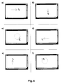
- FIGs. 4a through 4f represent consecutive diagrammatic views of a logic window, in a computer display operated by mouse 10.
- an approximately horizontal motion is issued to the cursor to set the scrolling axis status variable to "x".
- the operator can start scrolling concurrently in that direction to reach the desired data field in the least time possible.
- an approximately vertical motion is issued to the cursor to set the scrolling axis status variable to "y”.
- an approximately circular motion is issued to the cursor to change the scrolling scale status variable to "page-scale” (assuming the default scale is "line-scale”).
- linear patterns and circular patterns alter independent scrolling parameters and since circular patterns are memorized once detected, they can be combined to perform more complex scrolling commands (dynamic scrolling commands), in which scrolling scale settings and scrolling axis settings are performed in a single cursor movement.
- dynamic scrolling commands dynamic scrolling commands
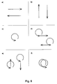
- figures 5a through 5f are examples of dynamic scrolling commands detected on mouse movement, according to the method of the invention.
- Fig. 5a sketches two isolated horizontal linear mouse motions, any of which result independently in setting the scrolling axis status variable to "x”.
- Fig. 5b sketches two isolated vertical linear mouse motions, any of which result independently in setting the scrolling axis status variable to "y”.
- Fig. 5c sketches an isolated circular mouse movement, which results in a change of the scrolling scale status variable. For example, if the scrolling scale status variable was set to "line-scale" before the pattern of fig. 5c is detected, after the pattern detection it will be set to "page-scale” and each incremental scrolling command triggered by operation of knob 41 will generate a whole-page scrolling of the displayed image.
- Fig. 5a sketches two isolated horizontal linear mouse motions, any of which result independently in setting the scrolling axis status variable to "x”.
- Fig. 5b sketches two isolated vertical linear mouse motions, any of which result independently in setting the scrolling axis status variable to "y”.
- Fig. 5c sketches an isolated circular mouse movement, which results
- FIG. 5d sketches an example of a combined dynamic scrolling command, comprising a circular movement followed by a linear horizontal movement. Any of these pattern combinations are interpreted as complex commands to upgrade the scrolling scale (e.g., to "page-scale") and set the scrolling axis to "x", in a single continuous mouse movement.
- Fig. 5e sketches dynamic scrolling commands analogous to the ones of fig. 5d, in this case setting the scrolling axis to "y”.
- two consecutive circular patterns are chained.
- this combination is used to set the scrolling scale to "layer-scale” (i.e., scrolling in or out the screen plane between successive 3D data layers).
- the supplementary control means 40 comprises a movable part 42, of approximately semicircular shape, mounted rotatably on an pivot axle 46, which is fixed to a baseboard 76.
- Movable part 42 acts as a housing for a rotation transducer, as explained herein below.
- Movable part 42 further comprises a half toothed-wheel 78, fixed to it and engaged with knob 41 through gear 87, so that knob 41 and movable part 42 are tightly coupled.
- Movable part 42, and hence knob 41 are both urged to respective released or equilibrium positions by spring means 47, which consists of a resilient wire 47 wound around pivot axle 46 and held in place by a pair of stops 49, fixed to movable part 42, and by another pair of stops 45, fixed to baseboard 76.
- Resilient wire 47 provides a restoring force of a first reluctance level.
- a second spring means 51 can be provided to produce the second reluctance level, so as to produce a steep transition between both levels giving a tactile feedback defining two operational displacement zones, as explained in detail later on herein.
- Resilient wire 51 is wounded around pivot axle 46 as well, but at a higher vertical position, separated from wire 47 by ring 48 and held in place by stops 49 and a pair of additional stops 53, also fixed to baseboard 76.
- wire 47 reacts to provide the first (lower) reluctance level.
- stops 49 and stops 53 and hence at a corresponding knob displacement
- one of the stops 49 gets in contact simultaneously with both wires 47 and 51, producing the second (higher) reluctance level.
- stops 45 and 53 can be made of a conducting material so that each pair of stops and their associated resilient wire act as electric switches indicating when the knob 41 is in its equilibrium position, in one case, or when the knob 41 has entered the low reluctance zone, in the other case.
- Rails 77 and 79 guide knob 41 through all its displacement range.
- Rail 77 is part of baseboard 76, and rail 79 is secured in its place by a pair of covers 81, rising from both sides of baseboard 76.
- Rail 79 is fixed to covers 81 through a pair of clamps 83.
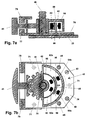
- FIGS 7a and 7b show detailed views of the mechanism and mounting of supplementary control means 40.
- the baseboard 76 is mounted directly on the printed circuit board 23 and fixed to it by three clamps 71, that provide stability to baseboard 76 and offset the force exerted by the operator's finger over knob 41.
- Baseboard 76 also contains the supporting axle 46, on which movable part 42 is pivotally mounted.
- Movable part 42 includes an inner, concentric semi-circular slotted skirt 80. At two angularly spaced locations, opto-coupler pairs 82a-84a and 82b-84b are placed as shown in figs. 7a and 7b. Each opto-coupler pair comprises a light emitting diode (LED) (82a and 82b) and a photo-transistor (84a and 84b) mounted directly on printed circuit board 23, and connected to it advantageously by soldering.
- LED light emitting diode
- 84a and 84b mounted directly on printed circuit board 23, and connected to it advantageously by soldering.
- the skirt 80 has a plurality of evenly spaced slots 86, and the skirt 80 is positioned to alternately block and let through light emitted by each LED 82a and 82b to their corresponding photo-transistors 84a and 84b, as movable part 42 rotates when knob 41 is operated.
- the baseboard 76 further includes a fixed skirt portion 88, extending circumferentially only over a portion of the circumferential extent as the slotted skirt 80, and having two complementary fixed slots 90, each positioned between the photo-transistors 84a and 84b and their corresponding light emitting diodes 82a and 82b.
- the fixed skirt portion 88 acts as a diaphragm or mask to enhance resolution of the rotation transducer, regardless of tolerances obtained when soldering the opto-coupler components to printed circuit board 23.
- a resolution of approximately 40 light transitions in a 45° rotation may be obtained for a skirt diameter of 2.5 centimeters, which allows a smooth enough operation.
- the light transitions detected by opto-couplers 82a-84a and 82b-84b represent incremental rotation units of movable part 42, and hence incremental displacement units of knob 41.
- the incremental information can be converted to absolute knob displacement by accumulating successive increments, starting from a default count at the equilibrium position. This approach allows a direct digital output with minimum part count, what is highly desirable in a low cost device as a mouse, and is compatible with the resolution and precision requirements of the scrolling control function of control means 40.
- the structure of the supplementary control means 40 disclosed herein provides a robust device of relatively simple assembly, that can be mounted directly on printed circuit board 23.
- the cylindrical geometry of the entire structure allows direct soldering of the opto-coupler components to printed circuit board 23, thus simplifying manufacturing and reducing overall cost.
- knob 41 since the shape of knob 41 produces minimum alteration to the contour of the mouse housing, and since it is movable along an approximately linear path (therefore maintaining always the same position relative to the mouse housing sides), this embodiment has the advantage of being highly ergonomic, facilitating the mouse handling and allowing precise operation of knob 41 while the mouse is moved in normal operation.
- the double reluctance characteristic (if implemented) of the supplementary control means and the way it relates to the operational method is diagrammed in fig 8a, in which the rotation detected by transducer 43 is represented as an angle measured from an equilibrium position 102, spanning a portion of circle 100.
- the corresponding positions of knob 41 are also represented at the left side of the figure.
- circle 100 several singularities are represented in the rotation range of the transducer 43, defining different zones represented as shaded areas.
- the corresponding singularities in the displacement range of knob 41 also represented.
- the zone marked as "LOWER RELUCTANCE” surrounds symmetrically the equilibrium position 102, inserted into the "HIGHER RELUCTANCE" zones, encountered as the transducer 43 is rotated in any direction (+ or -) overpassing the reluctance boundaries 106.
- the double reluctance characteristic allows a tactile feedback of displacement of knob 41, defining two operational modes, one for issuing single incremental scrolling commands, while the other mode is for gradual scrolling at selectable rates under the operator's control.
- a pair of single-command displacement thresholds 104 are defined inside the low reluctance zone, symmetrically located respect of the equilibrium position 102, defining three sub-zones in each half-range called A1, A2 and A3, as shown in fig. 8a.
- Thresholds 104 are trigger levels of the supplementary control signal, defined in accordance to actual dimensions and parameters of the supplementary control means 40, at approximately half the way between the equilibrium position 102 and reluctance boundaries 106.
- the single incremental scrolling commands are generated only when knob 41 is displaced overpassing thresholds 104, going from a lower absolute value of displacement to a higher one. In other words, a single incremental scrolling command is triggered when there is a transition from any of sub-zones A1 to the corresponding adjacent zone A2.
- the sign of the single incremental scrolling command is set in correspondence to the knob displacement sign.
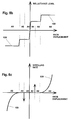
- Figs. 8b and 8c are a representation of the reluctance levels and the rate of generation of incremental scrolling commands correspondingly, as functions of the signed knob displacement.
- the reluctance singularities produced by spring means 47 and 59 are represented in curve 108.
- the arrows drawn in fig. 8c between corresponding sub-zones A1 and A2 represent the single incremental scrolling commands, and curve 109 represent an example of a possible function relating the rate of generation of incremental scrolling commands vs. the knob displacement.
- FIG. 9 A flow diagram of a routine realizing the method disclosed above is shown in fig. 9. It will be apparent to those skilled in the art that the functions represented in the flow diagram of fig. 9 can be realized by processing means residing inside the computer or alternatively inside the mouse housing, or any other combination. However, the first case is preferred since it is likely to reduce the mouse overall cost.
- Figure 10 is a block diagram of a computer system using the mouse and method of the present invention.
- a special mouse driver arrangement is used to translate the signals generated by mouse 10 into scrolling commands and cursor movement commands according to the method.
- the signal generated by the supplementary control means 40 is transmitted to the computer and processed by processing circuit means 92, which comprises software routines for calculating the actual knob position out of the incremental motion signals generated by transducer 43.
- Circuit means 92 also performs the functions represented by the flow diagram of fig.
- a first output SO1, representative of the knob displacement magnitude a second output SO2, which is a flag signal indicating when the knob has overpassed the reluctance boundaries 106 and is used as an automatic-scrolling enable signal; a third output SO3, which is a flag signal representing the sign of the knob displacement relative to its equilibrium position; plus, a fourth output SO4, which is a trigger signal generated each time the knob displacement crosses the single command threshold 104, according to what is explained herein before in relation to the operation of the supplementary control means 40.
- the output SO1 is fed to a scrolling timing generator circuit means 94, which comprises hardware/software timer means for generating periodic signals to trigger the incremental scrolling commands issued to an application program 95, at a variable rate under user control.
- the output SO2 is also fed to circuit means 94 for enabling the generation of incremental scrolling commands, only while knob 41 is in any of the high reluctance zones A3.
- the output SO3 conveys the scrolling direction within the selected axis and is fed directly into an incremental scrolling command generator circuit means 93.
- the scrolling commands generated by circuit means 93 are transferred to the application program 95 through a suitable software path, and by similar means as the cursor control commands.
- processing circuit means 91 contains software algorithms for detecting the pre-defined patterns in the cursor trail as it moves over the display means 96.
- Processing circuit means 91 generates two outputs: a first output SO5, representing the value of the scrolling axis status variable; plus, a second output SO6, representing the value of the scrolling scale status variable.
- Both status variables are kept by processing circuit means 91 and are dynamically updated at each real-time event generated by real time clock means 97, so that they reflect the information captured in the immediate past history of the cursor movement.
- the incremental scrolling commands generator 93 includes software routines that generate the corresponding commands upon receipt of the scrolling strobes generated by either scrolling timing generator circuit means 94 (for autonomous variable rate scrolling) or processing circuit means 92 (for step-by-step scrolling), as explained herein before.
- the particular incremental scrolling command generated by incremental commands generator 93 depends on the combined values of the scrolling axis status variable and the scrolling scale status variable generated by circuit means 91, plus the displacement sign variable generated by circuit means 92.
- the output generated by incremental scrolling commands generator 93 is linked to the available incremental scrolling routines of the application program to generate the corresponding visual effect on the display means 96. It will be apparent to those skilled in the art that this can be done through a variety of hardware/software techniques known in the art (e.g., a straight forward and compatible approach is through emulation of keyboard keys assigned to scrolling functions).
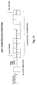
- the algorithms used for detecting pre-defined patterns in the cursor trail are based on sampling consecutive cursor positions at a fixed rate, and storing the x-y information in a two-dimensional shift register data structure (represented in fig. 11), to keep track of the cursor trail as the mouse cursor is moved on the display means.
- the system must include a real-time clock means to synchronize the sampling process. Since the algorithms are based on analyzing backwards in time the relative cursor positions considering the last cursor position as the origin, only incremental translation information needs to be stored in the shift register.
- circuit means 91 (fig.
- a real-time clock is theoretically needed to track successive cursor positions in time, it is not needed if a serial format is used in the communication link between mouse and computer, since the timing information is implicit in the data transmission rate set for the link.
- the incremental motion counts contained in the data packets comprising the serial format can be directly stored in the shift register data structure, obtaining the same results while requiring less computer resources.
- the precision of the real time period is not critical, since it is masked out by the flexibility of the pattern detection algorithms.
- Figures 12a and 12b show two examples of possible cursor trajectories.
- Figure 12a shows the trail generated by an almost horizontal cursor movement while figure 12b shows the trail generated by a circular cursor movement.
- the position of the cursor at any given time "t n " is shown as a shaded arrow, and the previous cursor positions stored in the shift register are drawn in broken lines, corresponding to previous times "t n-1 ", "t n-2 “, “t n-3 “, ... and so on.
- a number of parameters can then be calculated from the information present in the shift register at each real-time clock event, to detect the pattern "drawn" by the user with the mouse movement.
- the algorithms are simply based on comparing the magnitudes of asdx and asdy and setting the scrolling axis according to the greater of both.
- parameters sadx and sady are compared to their corresponding asdx and asdy. As can be seen in fig. 12b, for a circular trajectory, parameters asdx and asdy tend to be much smaller than their corresponding sadx and sady. Moreover, two additional parameters are defined to cooperate in the detection of circular patterns; the pattern length and the pattern size .
- the length of a pattern is defined as the number of consecutive real time events in which significant x-y mouse data has been entered in the shift register. According to the definition, a pattern length counter is obtained if the contents of a variable is incremented in each real-time event in which significant mouse movement is detected. When a real-time event takes place and no significant x-y mouse movement has been detected, the pattern length counter is reset to zero. Thus, the pattern length counter is a measure of the time used to "draw" the pattern.
- the size of a pattern is defined as the total physical distance tripped by the cursor in either axis to draw the pattern in the display means screen.
- the size of a pattern can be obtained as the absolute value of the sum of all incremental distance units the cursor has been moved in either axis, in each real-time event in which the pattern length counter was incremented.
- Circular patterns tend to have a greater length than linear patterns (approximately by a ⁇ factor). Furthermore, mouse operators tend to produce unintentional small mouse movements in normal operation, that might be accidentally detected as circular pattern commands. Therefore, in order to differentiate valid cursor movement commands from a number of scattered meaningless cursor movements, pattern length and size conditions are implemented in the algorithms. In this way, mouse movements with less than a pre-determined length threshold and a predetermined size threshold are filtered. Since circular patterns are useful only if they are drawn in a certain period of time and have at least a certain size, unintentional movements can be avoided by filtering small and short movements.
- Inequality 3 filters all movements but those in which the final distance between the starting and ending point along the "x" axis is at least k1 times smaller than the whole distance tripped by the cursor along the same axis.
- Inequality 5 filters all movements but those in which the whole distance tripped by the cursor along the "x" axis is at most k2 times greater that the overall distance tripped by the cursor along the "y" axis (quadrature condition).
- Inequality 6 is the dual of inequality 5 for the "y" axis.
- shift-registers of different sizes may be used for linear and circular pattern detection. Two identical sets of parameters are then calculated; short-case parameters and long-case parameters, for linear pattern detection and circular pattern detection respectively.
- a single shift-register with two synchronized tail pointers defining two different shift-register extents can also be used. Since linear patterns and circular patterns affect independent status variables, the double shift-register approach is more adequate for detecting combinations of patterns as explained herein below.
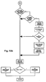
- the flow corresponding to the pattern detection algorithms is represented in figs. 13a and 13b.
- Fig. 14 shows a possible cursor trajectory to illustrate how combined mouse movements are detected. A plurality of successive cursor positions are shown at corresponding real-time events represented as marks t0 through t9.
- the cursor trail is analyzed and a match with a circular pattern is first tried. Upon a match, the corresponding status variable (i.e., the scrolling scale status variable) is updated accordingly.
- the same cursor trail information is then analyzed to detect a linear pattern (i.e., horizontal or vertical movement) and the corresponding status variable is altered accordingly (i.e., the scrolling axis status variable).
- the scrolling scale status variable is set to "line-scale" at time t0 in fig. 14, the circular pattern is detected approximately at real-time event t6 or t7, and memorized in the scrolling scale status variable, which is advanced to "page-scale".
- the scrolling axis is set at each real-time event as has been explained, it has a useful meaning only at time t9, where it will be set to "y”, according to the dominant axis of the last part of the cursor trajectory (short-case parameters). At that point, actuation of knob 41 will produce a vertical scrolling on a page basis, upwards or downwards depending on the sign of the knob displacement.
- the cursor trajectory shown in figure 10 looks like a complex command consisting of a circular pattern followed by a linear vertical pattern.
- this complex cursor trajectory is equivalent to a combined command to set the scrolling scale to "page-scale” and set the scrolling axis to "y”, in a single continuous mouse movement.
- the pattern detection algorithms are kept simple, since they only have to discriminate a vertical line from a horizontal one, or the existence of a circular movement, one independently of the other. Therefore, a richer and more flexible language is obtained between operator and computer, but with no sacrifice in simplicity of the pattern detection algorithms.
- scrolling scale status variable which is advanced to the next option whenever a circular pattern is detected.
- the scrolling scale is set to "layer-scale”
- the scrolling axis status variable is ignored, since it should be fixed to the "z" axis, so only the displacement sign is used to determine the scrolling heading (i.e., in or out of the screen plane). Since the pattern detection is performed at each real-time event, the shift register contents must be cleared as soon as a circular pattern is detected, to avoid double detection of the same circular pattern in consecutive real-time events.
- scrolling can be performed in different scales, along different axis and at a plurality of speeds, using only one finger of the hand that holds and moves the mouse.
- This allows the mouse 10 of the invention to be used as a virtual pointing device, not bounded by the physical screen limits, but still compatible with conventional mouse usage methods and applications.
- the advantage of the pattern set used i.e., a linear horizontal mouse motion, a linear vertical mouse motion and a circular mouse motion
- the pattern-to-command assignment disclosed herein is that all patterns are easily associated to the effect they produce on the display.
- a linear pattern can be intuitively associated to a gesture or sign to tell the computer that a scrolling direction parallel to that of the linear pattern is desired
- a circular pattern can be intuitively associated to a gesture to tell the computer that a scrolling scale altering the whole screen or window contents is desired.
- the gesture language is composed of only three elements that can be combined, the detection of each of the individual elements can be performed with great flexibility, providing a relaxed operation and a highly humanized computer-user interface.
Landscapes
- Engineering & Computer Science (AREA)
- General Engineering & Computer Science (AREA)
- Theoretical Computer Science (AREA)
- Human Computer Interaction (AREA)
- Physics & Mathematics (AREA)
- General Physics & Mathematics (AREA)
- Position Input By Displaying (AREA)
- Digital Computer Display Output (AREA)
Applications Claiming Priority (4)
| Application Number | Priority Date | Filing Date | Title |
|---|---|---|---|
| US08/014,388 US5313229A (en) | 1993-02-05 | 1993-02-05 | Mouse and method for concurrent cursor position and scrolling control |
| US14388 | 1993-02-05 | ||
| US08/105,901 US5374942A (en) | 1993-02-05 | 1993-08-12 | Mouse and method for concurrent cursor position and scrolling control |
| US105901 | 1993-08-12 |
Publications (1)
| Publication Number | Publication Date |
|---|---|
| EP0609819A1 true EP0609819A1 (de) | 1994-08-10 |
Family
ID=26686028
Family Applications (1)
| Application Number | Title | Priority Date | Filing Date |
|---|---|---|---|
| EP94101430A Withdrawn EP0609819A1 (de) | 1993-02-05 | 1994-02-01 | Maus und Verfahren zur gleichzeitigen Steuerung von Cursorstelle und Verschiebung |
Country Status (3)
| Country | Link |
|---|---|
| US (1) | US5374942A (de) |
| EP (1) | EP0609819A1 (de) |
| JP (1) | JPH06259189A (de) |
Cited By (17)
| Publication number | Priority date | Publication date | Assignee | Title |
|---|---|---|---|---|
| EP0662669A3 (de) * | 1994-01-06 | 1996-01-24 | Microsoft Corp | 3-D-Cursor-Positionssteuerungsvorrichtung. |
| US6097371A (en) * | 1996-01-02 | 2000-08-01 | Microsoft Corporation | System and method of adjusting display characteristics of a displayable data file using an ergonomic computer input device |
| US6531692B1 (en) | 1999-03-22 | 2003-03-11 | Microsoft Corporation | Optical coupling assembly for image sensing operator input device |
| WO2003067875A1 (en) * | 2002-02-06 | 2003-08-14 | Koninklijke Philips Electronics N.V. | Method and apparatus for scrolling electronic program guide (epg) and other textual information |
| WO2004008417A1 (en) * | 2002-07-10 | 2004-01-22 | Firstrand Bank Limited | Method and apparatus for obtaining a response from a subject |
| US6940488B1 (en) | 1994-01-06 | 2005-09-06 | Microsoft Corporation | System and method of adjusting display characteristics of a displayable data file using an ergonomic computer input device |
| US7296242B2 (en) * | 2000-05-01 | 2007-11-13 | Sony Corporation | Information processing apparatus and method and program and program storage medium |
| US7322011B2 (en) | 1994-01-06 | 2008-01-22 | Microsoft Corporation | System and method of adjusting display characteristics of a displayable data file using an ergonomic computer input device |
| US7398089B2 (en) | 2003-11-12 | 2008-07-08 | Research In Motion Ltd | Data-capable network prioritization with reduced delays in data service |
| CN103246368A (zh) * | 2012-02-01 | 2013-08-14 | 罗技欧洲公司 | 用于输入设备上的伪信号检测和补偿的系统和方法 |
| WO2015036036A1 (de) * | 2013-09-13 | 2015-03-19 | Steinberg Media Technologies Gmbh | Verfahren zur selektiven ansteuerung durch erkennung der vorzugsrichtung |
| US9535594B1 (en) | 2015-09-08 | 2017-01-03 | Apple Inc. | Devices, methods, and graphical user interfaces for moving a current focus using a touch-sensitive remote control |
| US9639241B2 (en) | 2015-06-18 | 2017-05-02 | Apple Inc. | Device, method, and graphical user interface for navigating media content |
| US9928029B2 (en) | 2015-09-08 | 2018-03-27 | Apple Inc. | Device, method, and graphical user interface for providing audiovisual feedback |
| WO2021011005A1 (en) * | 2019-07-18 | 2021-01-21 | Hewlett-Packard Development Company, L.P. | Pointer locating applets |
| US11922006B2 (en) | 2018-06-03 | 2024-03-05 | Apple Inc. | Media control for screensavers on an electronic device |
| US12321570B2 (en) | 2015-06-18 | 2025-06-03 | Apple Inc. | Device, method, and graphical user interface for navigating media content |
Families Citing this family (135)
| Publication number | Priority date | Publication date | Assignee | Title |
|---|---|---|---|---|
| US5889670A (en) | 1991-10-24 | 1999-03-30 | Immersion Corporation | Method and apparatus for tactilely responsive user interface |
| US5880411A (en) | 1992-06-08 | 1999-03-09 | Synaptics, Incorporated | Object position detector with edge motion feature and gesture recognition |
| US6028271A (en) | 1992-06-08 | 2000-02-22 | Synaptics, Inc. | Object position detector with edge motion feature and gesture recognition |
| US7532205B2 (en) * | 1992-06-08 | 2009-05-12 | Synaptics, Inc. | Object position detector with edge motion feature and gesture recognition |
| US6239389B1 (en) | 1992-06-08 | 2001-05-29 | Synaptics, Inc. | Object position detection system and method |
| DE69518148T2 (de) * | 1994-04-08 | 2001-03-22 | United Video Properties, Inc. | Interaktive abrollbare programmanzeige |
| JP2655527B2 (ja) * | 1994-09-13 | 1997-09-24 | 日本電気株式会社 | データ入力装置 |
| US5633657A (en) * | 1994-10-11 | 1997-05-27 | Falcon; Fernando D. | Mouse driver arrangement for providing advanced scrolling capabilities to a conventional mouse |
| US5495566A (en) * | 1994-11-22 | 1996-02-27 | Microsoft Corporation | Scrolling contents of a window |
| US5473745A (en) * | 1994-12-14 | 1995-12-05 | International Business Machines Corporation | Exposing and hiding a title bar behind its window using a visual cue |
| JPH08202281A (ja) * | 1995-01-30 | 1996-08-09 | Olympus Optical Co Ltd | 頭部装着型映像表示装置システム |
| US5611060A (en) * | 1995-02-22 | 1997-03-11 | Microsoft Corporation | Auto-scrolling during a drag and drop operation |
| US5691898A (en) * | 1995-09-27 | 1997-11-25 | Immersion Human Interface Corp. | Safe and low cost computer peripherals with force feedback for consumer applications |
| US6769128B1 (en) | 1995-06-07 | 2004-07-27 | United Video Properties, Inc. | Electronic television program guide schedule system and method with data feed access |
| US6166723A (en) * | 1995-11-17 | 2000-12-26 | Immersion Corporation | Mouse interface device providing force feedback |
| GB9522791D0 (en) * | 1995-11-07 | 1996-01-10 | Cambridge Consultants | Information retrieval and display systems |
| US5732228A (en) * | 1995-11-14 | 1998-03-24 | International Business Machines Corporation | Method and system for per widget graphical pointer control within a data processing system graphical user interface |
| US6100874A (en) | 1995-11-17 | 2000-08-08 | Immersion Corporation | Force feedback mouse interface |
| US5825308A (en) | 1996-11-26 | 1998-10-20 | Immersion Human Interface Corporation | Force feedback interface having isotonic and isometric functionality |
| US6061004A (en) * | 1995-11-26 | 2000-05-09 | Immersion Corporation | Providing force feedback using an interface device including an indexing function |
| US6219032B1 (en) | 1995-12-01 | 2001-04-17 | Immersion Corporation | Method for providing force feedback to a user of an interface device based on interactions of a controlled cursor with graphical elements in a graphical user interface |
| US6028593A (en) | 1995-12-01 | 2000-02-22 | Immersion Corporation | Method and apparatus for providing simulated physical interactions within computer generated environments |
| US8508469B1 (en) | 1995-12-01 | 2013-08-13 | Immersion Corporation | Networked applications including haptic feedback |
| US6078308A (en) * | 1995-12-13 | 2000-06-20 | Immersion Corporation | Graphical click surfaces for force feedback applications to provide user selection using cursor interaction with a trigger position within a boundary of a graphical object |
| US6300936B1 (en) | 1997-11-14 | 2001-10-09 | Immersion Corporation | Force feedback system including multi-tasking graphical host environment and interface device |
| US5936618A (en) * | 1996-04-19 | 1999-08-10 | U.S. Philips Corporation | Information display device with adaptive scroll speed |
| US5940073A (en) | 1996-05-03 | 1999-08-17 | Starsight Telecast Inc. | Method and system for displaying other information in a TV program guide |
| US6374255B1 (en) | 1996-05-21 | 2002-04-16 | Immersion Corporation | Haptic authoring |
| US5999169A (en) * | 1996-08-30 | 1999-12-07 | International Business Machines Corporation | Computer graphical user interface method and system for supporting multiple two-dimensional movement inputs |
| US6128006A (en) * | 1998-03-26 | 2000-10-03 | Immersion Corporation | Force feedback mouse wheel and other control wheels |
| US6636197B1 (en) | 1996-11-26 | 2003-10-21 | Immersion Corporation | Haptic feedback effects for control, knobs and other interface devices |
| US6956558B1 (en) | 1998-03-26 | 2005-10-18 | Immersion Corporation | Rotary force feedback wheels for remote control devices |
| US7489309B2 (en) | 1996-11-26 | 2009-02-10 | Immersion Corporation | Control knob with multiple degrees of freedom and force feedback |
| US6154201A (en) * | 1996-11-26 | 2000-11-28 | Immersion Corporation | Control knob with multiple degrees of freedom and force feedback |
| US6686911B1 (en) | 1996-11-26 | 2004-02-03 | Immersion Corporation | Control knob with control modes and force feedback |
| US8635649B2 (en) * | 1996-12-19 | 2014-01-21 | Gemstar Development Corporation | System and method for modifying advertisement responsive to EPG information |
| US6687906B1 (en) | 1996-12-19 | 2004-02-03 | Index Systems, Inc. | EPG with advertising inserts |
| US5963195A (en) * | 1996-12-19 | 1999-10-05 | International Business Machines Corporation | Hardware-selectable mouse movement |
| US5801691A (en) * | 1996-12-31 | 1998-09-01 | International Business Machines Corporation | Method and apparatus for mobile device screen reformatting utilizing hypertext |
| US5872566A (en) * | 1997-02-21 | 1999-02-16 | International Business Machines Corporation | Graphical user interface method and system that provides an inertial slider within a scroll bar |
| US5808568A (en) * | 1997-02-27 | 1998-09-15 | Primax Electronics, Ltd. | Finger operated module for generating encoding signals |
| US5874957A (en) * | 1997-02-28 | 1999-02-23 | International Business Machines Corporation | Method and apparatus for improved scrolling functionality in a graphical user interface utilizing a software tether |
| US5874961A (en) * | 1997-03-19 | 1999-02-23 | International Business Machines Corporation | Scroll bar amplification apparatus and method |
| US5963191A (en) * | 1997-03-25 | 1999-10-05 | International Business Machines Corporation | Method and system for denying graphical pointer access to a widget of a data processing system graphical user interface |
| US6292113B1 (en) | 1997-03-25 | 2001-09-18 | Primax Electronics Ltd. | Finger operated module for generating encoding signals |
| US6020876A (en) * | 1997-04-14 | 2000-02-01 | Immersion Corporation | Force feedback interface with selective disturbance filter |
| US6064370A (en) * | 1997-06-05 | 2000-05-16 | Kye Systems Corp. | Z-axis flywheel control of a computer input device |
| US5903267A (en) * | 1997-07-11 | 1999-05-11 | International Business Machines Corporation | Document interface mechanism and method for navigating through large documents |
| EP1036466B1 (de) | 1997-07-21 | 2003-03-26 | E Guide, Inc. | Verfahren zum navigieren in einem fernsehprogrammführer mit werbung |
| US6252579B1 (en) | 1997-08-23 | 2001-06-26 | Immersion Corporation | Interface device and method for providing enhanced cursor control with force feedback |
| US6292174B1 (en) | 1997-08-23 | 2001-09-18 | Immersion Corporation | Enhanced cursor control using limited-workspace force feedback devices |
| US5912667A (en) * | 1997-09-10 | 1999-06-15 | Primax Electronics Ltd. | Cursor control system for controlling a pop-up menu |
| US6157369A (en) | 1997-10-14 | 2000-12-05 | Logitech, Inc. | Optical-mechanical roller with ratchet |
| US6157381A (en) * | 1997-11-18 | 2000-12-05 | International Business Machines Corporation | Computer system, user interface component and method utilizing non-linear scroll bar |
| US6256011B1 (en) | 1997-12-03 | 2001-07-03 | Immersion Corporation | Multi-function control device with force feedback |
| US6208343B1 (en) | 1997-12-10 | 2001-03-27 | International Business Machines Corporation | Graphical user interface scroll bar that provides varied levels of access granularity |
| US7185355B1 (en) | 1998-03-04 | 2007-02-27 | United Video Properties, Inc. | Program guide system with preference profiles |
| US6067077A (en) | 1998-04-10 | 2000-05-23 | Immersion Corporation | Position sensing for force feedback devices |
| US20020095676A1 (en) | 1998-05-15 | 2002-07-18 | Robert A. Knee | Interactive television program guide system for determining user values for demographic categories |
| EP1078353A4 (de) | 1998-05-20 | 2004-04-28 | Kwan-Ho Chan | Finger-kontrollierte computer-maus |
| US6707443B2 (en) | 1998-06-23 | 2004-03-16 | Immersion Corporation | Haptic trackball device |
| US6898762B2 (en) | 1998-08-21 | 2005-05-24 | United Video Properties, Inc. | Client-server electronic program guide |
| USD412898S (en) | 1998-08-27 | 1999-08-17 | Microsoft Corporation | Computer mouse |
| US7002552B1 (en) * | 1999-04-06 | 2006-02-21 | Microsoft Corporation | Computer input device with digit support and natural position actuators |
| AU6040999A (en) * | 1998-09-14 | 2000-04-03 | Microsoft Corporation | Input device with forward/backward control |
| US7038667B1 (en) | 1998-10-26 | 2006-05-02 | Immersion Corporation | Mechanisms for control knobs and other interface devices |
| US6204846B1 (en) | 1999-02-16 | 2001-03-20 | International Business Machines Corporation | Data set user interface control for use in accessing information in a computer |
| US6664947B1 (en) * | 1999-02-24 | 2003-12-16 | Gueorgui K. Vinogradov | Safe and handy pointing device |
| US6339438B1 (en) | 1999-07-27 | 2002-01-15 | International Business Machines Corporation | Scroll bar with integrated advertisement |
| US6545667B1 (en) | 1999-08-23 | 2003-04-08 | David M. Lilenfield | Apparatus for a convenient and comfortable cursor control device |
| US6564168B1 (en) | 1999-09-14 | 2003-05-13 | Immersion Corporation | High-resolution optical encoder with phased-array photodetectors |
| US7385587B1 (en) | 1999-09-24 | 2008-06-10 | Lenovo (Singapore) Pte. Ltd. | Asymmetrical computer mouse design with extended thumb button |
| US6693626B1 (en) | 1999-12-07 | 2004-02-17 | Immersion Corporation | Haptic feedback using a keyboard device |
| US6556150B1 (en) * | 2000-03-24 | 2003-04-29 | Microsoft Corporation | Ergonomic computer input device |
| US6924787B2 (en) * | 2000-04-17 | 2005-08-02 | Immersion Corporation | Interface for controlling a graphical image |
| TW543871U (en) * | 2000-06-09 | 2003-07-21 | Meng-Yu Wei | Control device for mouse scrolling operation |
| JP4013454B2 (ja) | 2000-06-23 | 2007-11-28 | 富士ゼロックス株式会社 | ポインティングデバイスおよび情報処理装置 |
| US7084854B1 (en) | 2000-09-28 | 2006-08-01 | Immersion Corporation | Actuator for providing tactile sensations and device for directional tactile sensations |
| US6727889B2 (en) | 2001-09-14 | 2004-04-27 | Stephen W. Shaw | Computer mouse input device with multi-axis palm control |
| US7623114B2 (en) | 2001-10-09 | 2009-11-24 | Immersion Corporation | Haptic feedback sensations based on audio output from computer devices |
| US7038664B2 (en) * | 2001-11-01 | 2006-05-02 | Fellowes, Inc. | Input device for scrolling a computer display |
| US7009599B2 (en) * | 2001-11-20 | 2006-03-07 | Nokia Corporation | Form factor for portable device |
| US6904823B2 (en) | 2002-04-03 | 2005-06-14 | Immersion Corporation | Haptic shifting devices |
| US20040012568A1 (en) * | 2002-07-22 | 2004-01-22 | Velikov Ivan Valkov | Flat mouse |
| US7958455B2 (en) * | 2002-08-01 | 2011-06-07 | Apple Inc. | Mode activated scrolling |
| AU2003285886A1 (en) | 2002-10-15 | 2004-05-04 | Immersion Corporation | Products and processes for providing force sensations in a user interface |
| US7086032B2 (en) * | 2003-02-20 | 2006-08-01 | Adobe Systems Incorporated | System and method for representation of object animation within presentations of software application programs |
| US7404149B2 (en) * | 2003-03-28 | 2008-07-22 | International Business Machines Corporation | User-defined assistive GUI glue |
| US7280095B2 (en) * | 2003-04-30 | 2007-10-09 | Immersion Corporation | Hierarchical methods for generating force feedback effects |
| WO2004111819A1 (en) | 2003-06-09 | 2004-12-23 | Immersion Corporation | Interactive gaming systems with haptic feedback |
| US6986614B2 (en) * | 2003-07-31 | 2006-01-17 | Microsoft Corporation | Dual navigation control computer keyboard |
| US20050030279A1 (en) * | 2003-08-08 | 2005-02-10 | Liang Fu | Multi-functional pointing and control device |
| US20070130515A1 (en) * | 2003-11-28 | 2007-06-07 | Koninklijke Phillips Electronics N.V. | System for displaying images with multiple attributes |
| US7742036B2 (en) | 2003-12-22 | 2010-06-22 | Immersion Corporation | System and method for controlling haptic devices having multiple operational modes |
| US7283120B2 (en) * | 2004-01-16 | 2007-10-16 | Immersion Corporation | Method and apparatus for providing haptic feedback having a position-based component and a predetermined time-based component |
| TWI235945B (en) * | 2004-02-18 | 2005-07-11 | Benq Corp | Mouse device |
| TWI269206B (en) * | 2004-05-05 | 2006-12-21 | Sunplus Technology Co Ltd | Setting device for changing the resolution of the track of a multi-step mouse |
| JP4684794B2 (ja) * | 2005-08-04 | 2011-05-18 | 富士通コンポーネント株式会社 | 操作デバイス、電子書籍装置及び電子機器 |
| US7788266B2 (en) | 2005-08-26 | 2010-08-31 | Veveo, Inc. | Method and system for processing ambiguous, multi-term search queries |
| US20070080944A1 (en) * | 2005-10-07 | 2007-04-12 | Parees Benjamin M | Mouse with disengageable scroll function |
| US9113107B2 (en) | 2005-11-08 | 2015-08-18 | Rovi Guides, Inc. | Interactive advertising and program promotion in an interactive television system |
| US8380726B2 (en) | 2006-03-06 | 2013-02-19 | Veveo, Inc. | Methods and systems for selecting and presenting content based on a comparison of preference signatures from multiple users |
| US8316394B2 (en) | 2006-03-24 | 2012-11-20 | United Video Properties, Inc. | Interactive media guidance application with intelligent navigation and display features |
| US7898523B1 (en) * | 2006-06-09 | 2011-03-01 | Ronald Van Meter | Device for controlling on-screen pointer |
| TW200813806A (en) * | 2006-06-27 | 2008-03-16 | Ibm | Method, program, and data processing system for modifying shape of display object |
| US20080007527A1 (en) * | 2006-07-07 | 2008-01-10 | Creative Technology Ltd | Modifiable mouse with a biased switch and a method for modifying a mouse |
| EP3438796A1 (de) | 2006-09-13 | 2019-02-06 | Immersion Corporation | Systeme und verfahren für kasinospielhaptik |
| US20080082940A1 (en) * | 2006-09-29 | 2008-04-03 | Morris Robert P | Methods, systems, and computer program products for controlling presentation of a resource based on position or movement of a selector and presentable content |
| US8832742B2 (en) | 2006-10-06 | 2014-09-09 | United Video Properties, Inc. | Systems and methods for acquiring, categorizing and delivering media in interactive media guidance applications |
| US8756516B2 (en) * | 2006-10-31 | 2014-06-17 | Scenera Technologies, Llc | Methods, systems, and computer program products for interacting simultaneously with multiple application programs |
| US7801888B2 (en) | 2007-03-09 | 2010-09-21 | Microsoft Corporation | Media content search results ranked by popularity |
| US20090096747A1 (en) * | 2007-10-10 | 2009-04-16 | Zippy Technology Corp. | Method of rolling picture using input device |
| US8943539B2 (en) | 2007-11-21 | 2015-01-27 | Rovi Guides, Inc. | Enabling a friend to remotely modify user data |
| US9486292B2 (en) | 2008-02-14 | 2016-11-08 | Immersion Corporation | Systems and methods for real-time winding analysis for knot detection |
| US20100033426A1 (en) * | 2008-08-11 | 2010-02-11 | Immersion Corporation, A Delaware Corporation | Haptic Enabled Gaming Peripheral for a Musical Game |
| US10345996B2 (en) | 2008-10-22 | 2019-07-09 | Merge Healthcare Solutions Inc. | User interface systems and methods |
| US10768785B2 (en) | 2008-10-22 | 2020-09-08 | Merge Healthcare Solutions Inc. | Pressure sensitive manipulation of medical image data |
| US20100100849A1 (en) | 2008-10-22 | 2010-04-22 | Dr Systems, Inc. | User interface systems and methods |
| US10019081B2 (en) * | 2009-01-15 | 2018-07-10 | International Business Machines Corporation | Functionality switching in pointer input devices |
| US9104791B2 (en) | 2009-05-28 | 2015-08-11 | Immersion Corporation | Systems and methods for editing a model of a physical system for a simulation |
| US8314772B1 (en) | 2009-08-28 | 2012-11-20 | Coe Stanley S | Computer mouse |
| US9166714B2 (en) | 2009-09-11 | 2015-10-20 | Veveo, Inc. | Method of and system for presenting enriched video viewing analytics |
| US8359616B2 (en) | 2009-09-30 | 2013-01-22 | United Video Properties, Inc. | Systems and methods for automatically generating advertisements using a media guidance application |
| US8542105B2 (en) | 2009-11-24 | 2013-09-24 | Immersion Corporation | Handheld computer interface with haptic feedback |
| US8614677B2 (en) | 2010-11-02 | 2013-12-24 | Giga-Byte Technology Co., Ltd. | Mouse with adjustable switch |
| US8797350B2 (en) | 2010-12-20 | 2014-08-05 | Dr Systems, Inc. | Dynamic customizable human-computer interaction behavior |
| US9736524B2 (en) | 2011-01-06 | 2017-08-15 | Veveo, Inc. | Methods of and systems for content search based on environment sampling |
| CN102262508B (zh) * | 2011-07-21 | 2013-03-06 | 福州锐达数码科技有限公司 | 通过鼠标轨迹生成度量工具的方法 |
| US20130076626A1 (en) * | 2011-09-28 | 2013-03-28 | Robert Banik | Therapeutic human interface device |
| US9372612B2 (en) * | 2011-10-31 | 2016-06-21 | Microsoft Technology Licensing, Llc | Exposing inertial snap points |
| US8994755B2 (en) * | 2011-12-20 | 2015-03-31 | Alcatel Lucent | Servers, display devices, scrolling methods and methods of generating heatmaps |
| US20130179812A1 (en) * | 2012-01-10 | 2013-07-11 | Gilles Serge BianRosa | System and method for navigating a user interface using a touch-enabled input device |
| US9147198B2 (en) | 2013-01-10 | 2015-09-29 | Rovi Technologies Corporation | Systems and methods for providing an interface for data driven media placement |
| US9866924B2 (en) | 2013-03-14 | 2018-01-09 | Immersion Corporation | Systems and methods for enhanced television interaction |
| US11194461B2 (en) * | 2019-01-15 | 2021-12-07 | Fujifilm Medical Systems U.S.A., Inc. | Smooth image scrolling with dynamic scroll extension |
Citations (7)
| Publication number | Priority date | Publication date | Assignee | Title |
|---|---|---|---|---|
| DE3635281A1 (de) * | 1985-10-16 | 1987-04-16 | Hitachi Ltd | Bildschirmanzeigeeinrichtung |
| EP0242774A1 (de) * | 1986-04-16 | 1987-10-28 | Siemens Aktiengesellschaft | Anordnung zum Verschieben von Zeichen auf dem Bildschirm eines Sichtgerätes |
| GB2217129A (en) * | 1988-04-06 | 1989-10-18 | Sony Corp | Device for generating control data |
| WO1990005972A1 (en) * | 1988-11-14 | 1990-05-31 | Wang Laboratories, Inc. | Squeezable control device for computer display systems |
| WO1991020072A1 (en) * | 1990-06-15 | 1991-12-26 | Empruve, Inc. | System for displaying information |
| EP0463772A2 (de) * | 1990-06-14 | 1992-01-02 | Sony Corporation | Koordinatendatenverarbeitungsgerät mit Zeigereinrichtung |
| EP0494106A1 (de) * | 1991-01-03 | 1992-07-08 | Xerox Corporation | Vorrichtung zum Anzeigen von Gebieten auf einem Sichtgerät |
Family Cites Families (3)
| Publication number | Priority date | Publication date | Assignee | Title |
|---|---|---|---|---|
| JPS60186925A (ja) * | 1984-03-06 | 1985-09-24 | Nec Corp | ジヨイステイツク |
| US4891632A (en) * | 1988-01-20 | 1990-01-02 | King Phoenix Co., Ltd. | Computer graphic drawing apparatus with coarse and fine controls |
| US5261054A (en) * | 1988-12-22 | 1993-11-09 | Sun Microsystems, Inc. | System for storing a history of sampled pointer signals when a pointer interrupt routine is interrupted by a higher priority interrupt |
-
1993
- 1993-08-12 US US08/105,901 patent/US5374942A/en not_active Expired - Fee Related
-
1994
- 1994-02-01 EP EP94101430A patent/EP0609819A1/de not_active Withdrawn
- 1994-02-03 JP JP6011773A patent/JPH06259189A/ja active Pending
Patent Citations (8)
| Publication number | Priority date | Publication date | Assignee | Title |
|---|---|---|---|---|
| DE3635281A1 (de) * | 1985-10-16 | 1987-04-16 | Hitachi Ltd | Bildschirmanzeigeeinrichtung |
| EP0242774A1 (de) * | 1986-04-16 | 1987-10-28 | Siemens Aktiengesellschaft | Anordnung zum Verschieben von Zeichen auf dem Bildschirm eines Sichtgerätes |
| GB2217129A (en) * | 1988-04-06 | 1989-10-18 | Sony Corp | Device for generating control data |
| WO1990005972A1 (en) * | 1988-11-14 | 1990-05-31 | Wang Laboratories, Inc. | Squeezable control device for computer display systems |
| US5122785A (en) * | 1988-11-14 | 1992-06-16 | Wang Laboratories, Inc. | Squeezable control device for computer display system |
| EP0463772A2 (de) * | 1990-06-14 | 1992-01-02 | Sony Corporation | Koordinatendatenverarbeitungsgerät mit Zeigereinrichtung |
| WO1991020072A1 (en) * | 1990-06-15 | 1991-12-26 | Empruve, Inc. | System for displaying information |
| EP0494106A1 (de) * | 1991-01-03 | 1992-07-08 | Xerox Corporation | Vorrichtung zum Anzeigen von Gebieten auf einem Sichtgerät |
Cited By (37)
| Publication number | Priority date | Publication date | Assignee | Title |
|---|---|---|---|---|
| US6940488B1 (en) | 1994-01-06 | 2005-09-06 | Microsoft Corporation | System and method of adjusting display characteristics of a displayable data file using an ergonomic computer input device |
| US5963197A (en) * | 1994-01-06 | 1999-10-05 | Microsoft Corporation | 3-D cursor positioning device |
| US7322011B2 (en) | 1994-01-06 | 2008-01-22 | Microsoft Corporation | System and method of adjusting display characteristics of a displayable data file using an ergonomic computer input device |
| EP0662669A3 (de) * | 1994-01-06 | 1996-01-24 | Microsoft Corp | 3-D-Cursor-Positionssteuerungsvorrichtung. |
| US6281881B1 (en) | 1996-01-02 | 2001-08-28 | Microsoft Corporation | System and method of adjusting display characteristics of a displayable data file using an ergonomic computer input device |
| US6097371A (en) * | 1996-01-02 | 2000-08-01 | Microsoft Corporation | System and method of adjusting display characteristics of a displayable data file using an ergonomic computer input device |
| US6531692B1 (en) | 1999-03-22 | 2003-03-11 | Microsoft Corporation | Optical coupling assembly for image sensing operator input device |
| US7296242B2 (en) * | 2000-05-01 | 2007-11-13 | Sony Corporation | Information processing apparatus and method and program and program storage medium |
| WO2003067875A1 (en) * | 2002-02-06 | 2003-08-14 | Koninklijke Philips Electronics N.V. | Method and apparatus for scrolling electronic program guide (epg) and other textual information |
| WO2004008417A1 (en) * | 2002-07-10 | 2004-01-22 | Firstrand Bank Limited | Method and apparatus for obtaining a response from a subject |
| US7398089B2 (en) | 2003-11-12 | 2008-07-08 | Research In Motion Ltd | Data-capable network prioritization with reduced delays in data service |
| USRE43523E1 (en) | 2003-11-12 | 2012-07-17 | Research In Motion Limited | Data-capable network prioritization with reduced delays in data service |
| CN103246368A (zh) * | 2012-02-01 | 2013-08-14 | 罗技欧洲公司 | 用于输入设备上的伪信号检测和补偿的系统和方法 |
| EP2624105A3 (de) * | 2012-02-01 | 2016-04-13 | Logitech Europe S.A. | System und Verfahren zur Störsignalerkennung und Ausgleich auf einer Eingabevorrichtung |
| WO2015036036A1 (de) * | 2013-09-13 | 2015-03-19 | Steinberg Media Technologies Gmbh | Verfahren zur selektiven ansteuerung durch erkennung der vorzugsrichtung |
| US9652125B2 (en) | 2015-06-18 | 2017-05-16 | Apple Inc. | Device, method, and graphical user interface for navigating media content |
| US10073592B2 (en) | 2015-06-18 | 2018-09-11 | Apple Inc. | Device, method, and graphical user interface for navigating media content |
| US9639241B2 (en) | 2015-06-18 | 2017-05-02 | Apple Inc. | Device, method, and graphical user interface for navigating media content |
| US12321570B2 (en) | 2015-06-18 | 2025-06-03 | Apple Inc. | Device, method, and graphical user interface for navigating media content |
| US11816303B2 (en) | 2015-06-18 | 2023-11-14 | Apple Inc. | Device, method, and graphical user interface for navigating media content |
| US10572109B2 (en) | 2015-06-18 | 2020-02-25 | Apple Inc. | Device, method, and graphical user interface for navigating media content |
| US10545635B2 (en) | 2015-06-18 | 2020-01-28 | Apple Inc. | Device, method, and graphical user interface for navigating media content |
| US10073591B2 (en) | 2015-06-18 | 2018-09-11 | Apple Inc. | Device, method, and graphical user interface for navigating media content |
| US9990113B2 (en) | 2015-09-08 | 2018-06-05 | Apple Inc. | Devices, methods, and graphical user interfaces for moving a current focus using a touch-sensitive remote control |
| US10963130B2 (en) | 2015-09-08 | 2021-03-30 | Apple Inc. | Devices, methods, and graphical user interfaces for moving a current focus using a touch-sensitive remote control |
| US10474333B2 (en) | 2015-09-08 | 2019-11-12 | Apple Inc. | Devices, methods, and graphical user interfaces for moving a current focus using a touch-sensitive remote control |
| DK201500586A1 (en) * | 2015-09-08 | 2017-04-03 | Apple Inc | Devices, Methods, and Graphical User Interfaces for Moving a Current Focus Using a Touch-Sensitive Remote Control |
| US9928029B2 (en) | 2015-09-08 | 2018-03-27 | Apple Inc. | Device, method, and graphical user interface for providing audiovisual feedback |
| US10599394B2 (en) | 2015-09-08 | 2020-03-24 | Apple Inc. | Device, method, and graphical user interface for providing audiovisual feedback |
| US9535594B1 (en) | 2015-09-08 | 2017-01-03 | Apple Inc. | Devices, methods, and graphical user interfaces for moving a current focus using a touch-sensitive remote control |
| US10152300B2 (en) | 2015-09-08 | 2018-12-11 | Apple Inc. | Device, method, and graphical user interface for providing audiovisual feedback |
| US11262890B2 (en) | 2015-09-08 | 2022-03-01 | Apple Inc. | Devices, methods, and graphical user interfaces for moving a current focus using a touch-sensitive remote control |
| US11635876B2 (en) | 2015-09-08 | 2023-04-25 | Apple Inc. | Devices, methods, and graphical user interfaces for moving a current focus using a touch-sensitive remote control |
| DK179093B1 (en) * | 2015-09-08 | 2017-10-23 | Apple Inc | Devices, Methods, and Graphical User Interfaces for Moving a Current Focus Using a Touch-Sensitive Remote Control |
| US11960707B2 (en) | 2015-09-08 | 2024-04-16 | Apple Inc. | Devices, methods, and graphical user interfaces for moving a current focus using a touch-sensitive remote control |
| US11922006B2 (en) | 2018-06-03 | 2024-03-05 | Apple Inc. | Media control for screensavers on an electronic device |
| WO2021011005A1 (en) * | 2019-07-18 | 2021-01-21 | Hewlett-Packard Development Company, L.P. | Pointer locating applets |
Also Published As
| Publication number | Publication date |
|---|---|
| US5374942A (en) | 1994-12-20 |
| JPH06259189A (ja) | 1994-09-16 |
Similar Documents
| Publication | Publication Date | Title |
|---|---|---|
| US5313229A (en) | Mouse and method for concurrent cursor position and scrolling control | |
| US5374942A (en) | Mouse and method for concurrent cursor position and scrolling control | |
| US5963197A (en) | 3-D cursor positioning device | |
| EP1669844A2 (de) | Fernbedienung mit Touchpad und Verfahren | |
| EP2040151A2 (de) | Eingabesystem mit Positionserkennungsvorrichtung | |
| WO1997022050A1 (en) | Computer display cursor controller with serial interface | |
| WO1998000775A9 (en) | Touchpad with scroll and pan regions | |
| EP0880383A1 (de) | Auslöser betätigte elektronische vorrichtung | |
| JPH11194863A (ja) | タッチ入力検知方法及びタッチ入力検知装置 | |
| JPH11194891A (ja) | マウスポインティングデバイス | |
| US5579032A (en) | Pointing device for a computer system | |
| JPS59127143A (ja) | 手操作形計算機制御装置 | |
| KR100473843B1 (ko) | 정보선택장치및방법,휴대정보단말기용정보선택장치및방법 | |
| EP1019895B1 (de) | Universale eingabevorrichtung und system | |
| JPH0366690B2 (de) | ||
| JPH02115921A (ja) | スライドホール式座標入力装置 | |
| JPH01260523A (ja) | マウス | |
| JPH07319620A (ja) | マウス型情報入力装置 | |
| JPH10105332A (ja) | タッチパネル装置 | |
| JPH0540571A (ja) | 3次元位置入力方法および3次元位置入力装置 | |
| JPS6125232A (ja) | 入力装置 | |
| JPH086709A (ja) | ポインティングデバイス並びに情報処理装置の情報入力装置並びに携帯型情報処理端末装置 | |
| JPS60175137A (ja) | 手操作形計算機制御装置 | |
| JP2862015B2 (ja) | ポインティングデバイス | |
| JPH07191791A (ja) | 仮想キーボード |
Legal Events
| Date | Code | Title | Description |
|---|---|---|---|
| PUAI | Public reference made under article 153(3) epc to a published international application that has entered the european phase |
Free format text: ORIGINAL CODE: 0009012 |
|
| AK | Designated contracting states |
Kind code of ref document: A1 Designated state(s): AT BE CH DE DK ES FR GB GR IE IT LI LU MC NL PT SE |
|
| STAA | Information on the status of an ep patent application or granted ep patent |
Free format text: STATUS: THE APPLICATION IS DEEMED TO BE WITHDRAWN |
|
| 18D | Application deemed to be withdrawn |
Effective date: 19950211 |