EP0609862A2 - Stromschiene und Adapter - Google Patents
Stromschiene und Adapter Download PDFInfo
- Publication number
- EP0609862A2 EP0609862A2 EP94101560A EP94101560A EP0609862A2 EP 0609862 A2 EP0609862 A2 EP 0609862A2 EP 94101560 A EP94101560 A EP 94101560A EP 94101560 A EP94101560 A EP 94101560A EP 0609862 A2 EP0609862 A2 EP 0609862A2
- Authority
- EP
- European Patent Office
- Prior art keywords
- socket
- plug
- along
- electrical
- conductors
- Prior art date
- Legal status (The legal status is an assumption and is not a legal conclusion. Google has not performed a legal analysis and makes no representation as to the accuracy of the status listed.)
- Withdrawn
Links
- 239000004020 conductor Substances 0.000 claims abstract description 67
- 239000000463 material Substances 0.000 claims abstract description 10
- 238000003780 insertion Methods 0.000 claims abstract description 6
- 230000037431 insertion Effects 0.000 claims abstract description 6
- 239000012811 non-conductive material Substances 0.000 claims abstract description 4
- 229910001369 Brass Inorganic materials 0.000 claims description 2
- RYGMFSIKBFXOCR-UHFFFAOYSA-N Copper Chemical compound [Cu] RYGMFSIKBFXOCR-UHFFFAOYSA-N 0.000 claims description 2
- 229910052782 aluminium Inorganic materials 0.000 claims description 2
- XAGFODPZIPBFFR-UHFFFAOYSA-N aluminium Chemical compound [Al] XAGFODPZIPBFFR-UHFFFAOYSA-N 0.000 claims description 2
- 239000010951 brass Substances 0.000 claims description 2
- 229910052802 copper Inorganic materials 0.000 claims description 2
- 239000010949 copper Substances 0.000 claims description 2
- 230000005611 electricity Effects 0.000 claims description 2
- 239000004411 aluminium Substances 0.000 claims 1
- 206010014405 Electrocution Diseases 0.000 description 2
- 229910052751 metal Inorganic materials 0.000 description 2
- 239000002184 metal Substances 0.000 description 2
- 230000004048 modification Effects 0.000 description 2
- 238000012986 modification Methods 0.000 description 2
- 238000010276 construction Methods 0.000 description 1
- 238000005259 measurement Methods 0.000 description 1
- 230000002441 reversible effect Effects 0.000 description 1
- AFJYYKSVHJGXSN-KAJWKRCWSA-N selamectin Chemical compound O1[C@@H](C)[C@H](O)[C@@H](OC)C[C@@H]1O[C@@H]1C(/C)=C/C[C@@H](O[C@]2(O[C@@H]([C@@H](C)CC2)C2CCCCC2)C2)C[C@@H]2OC(=O)[C@@H]([C@]23O)C=C(C)C(=N\O)/[C@H]3OC\C2=C/C=C/[C@@H]1C AFJYYKSVHJGXSN-KAJWKRCWSA-N 0.000 description 1
Images


Classifications
-
- H—ELECTRICITY
- H01—ELECTRIC ELEMENTS
- H01R—ELECTRICALLY-CONDUCTIVE CONNECTIONS; STRUCTURAL ASSOCIATIONS OF A PLURALITY OF MUTUALLY-INSULATED ELECTRICAL CONNECTING ELEMENTS; COUPLING DEVICES; CURRENT COLLECTORS
- H01R25/00—Coupling parts adapted for simultaneous co-operation with two or more identical counterparts, e.g. for distributing energy to two or more circuits
- H01R25/14—Rails or bus-bars constructed so that the counterparts can be connected thereto at any point along their length
Definitions
- the present invention relates to a device of a plug and socket wherein the socket is used as a line for plugs that can slide and be located at any point along it's length.
- the standard known plug and sockets have many disadvantages. Every country has its own standard, and there are differences in the countries in the various standards such as, shape of the pins, the holes, and their sizes. These differences cause aggravation to electric appliance users who want to use their appliances in different countries.
- the pins are also used to hold the plug to the socket (in addition to their use enabling current to flow).
- the link between the plug and the socket is too strong, it is hard to plug in or remove the plug.
- the plug just slips out of the socket.
- the present invention overcomes the above mentioned disadvantages of the standard well-known plug and socket, and in addition has many other advantages.
- the plug and socket device of the present invention one can connect the plug into the socket in the dark. Blind people can connect the plug into the socket without any danger. There are no worries of electrocution because no one can touch the connection points between the plug and the socket.
- the socket according to the invention can hold many plugs along its length. It is possible to connect the plugs next to one another. A plug can "travel" along the length of the socket while in continuous use, as there is a constant current along the whole length.
- the connection between the plug and socket is stable, simple, strong, and allows for a plug socket connection on the ceiling (like light implements) which can not be done with existing standard known plugs and sockets.
- connection of the plug to the wall is simple, aesthetic and does not require special work done to the wall. It is possible to connect the existing known plug to a socket according to the present invention by simple modification. It is also possible to connect the socket to a standard known socket by simple modification (connecting standard plug pins to the socket).
- the conductive bodies in the plug and the conductors of the socket make contact on the backside of the socket which is far from the body of the plug.
- the advantage of this particular feature is that it minimizes the risk of electrocution.
- the specific contour of the socket's groove prevents a foreign body, for example a hammer, from being inserted and touching the electric conductors, and enables only bodies with the appropriate matching contour to reach the socket's conductors (like a lock and key).
- the present invention relates to an electrical plug and socket device wherein the socket is an elongated body made of a rigid non-conductive material with two or three grooves along its body and a conductor connected to a power source passes inside and through every groove and at least one "station" for insertion or removal of the plug is located along said socket and wherein the plug is comprised of a cover and a body both made from non-conductive rigid material, two or three rigid conductive bodies located at the underbody of the plug and connected to the electrical cable passing through the cover, and said conductive bodies are contoured and located such that they fit for entry, sliding and grasping of the socket's grooves while continuously touching the sockets conductors inside said grooves.
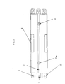
- Fig. 1 describes with Isometrics the socket according to the invention.
- the socket is an elongated body (1) and through it pass three conductors (2), (3) and (4).
- the conductors (2) and (3) serve as current passage lines and conductor (4) for grounding.
- the line connected to the ground is optional, and the socket can operate without it.
- These three lines are found along three grooves (5), (6), and (7) that pass along the length of both sides of the body (5) and (6) and one along its middle (7).
- the two current lines and the line connected to the ground protrude from the two sides of the path for optional connection of the socket to an external source of current and also as an optional connection to another socket. Its also possible to make a body without protruding conductors in the case when one does not want the option of connecting the sockets one to another.
- the conducting lines 2 and 3 although they protrude at the ends as a planar elongated conductor, inside the body they bend at a 90 degree angle. This can be seen in detail in figure 3D. In this figure, it is somewhat difficult to see the conductors that are perpendicular to conductors 2 and 3 that give the 90 degree angle.
- the main conductor that is perpendicularly attached to conductor 2 is 2c and it together with 2 creates a 90 degree angled conductor.
- These conductors can be two planar straight conductors that can be connected perpendicularly, or one conductor that is angled at 90 degrees.
- the lower part of the socket (9) may be fixed to the wall, the ceiling, or to any other area with screws (10) or screws (12). Afterwards the conductors and the upper part of the socket are connected to the lower part by inserting it into the lower part and by screws (12).
- Fig. 2 describes the socket from an overview.
- the groove (7) that uses the ground conductor (4) passes along the length of the socket.
- the entrance and exit station (8) allows for inserting and removing of the plug.
- the metal conductors (2), (3), and (4) protrude from the two sides of the plug for and optional connection to a source of current and for the possibility of connecting an additional socket.
- the screws (12) and (12a) are used to connect the upper part of the socket to its lower part that is attached to the wall (or the appendage of the entire socket to the wall).
- the two parts of the socket, the upper and the lower parts (not including the conductors) are made of an isolating plastic material.
- Fig. 3 illustrates a cross-section of the various parts of the socket, separately and assembled.
- Fig. 3a describes in cross-section of the lower part of the socket. (This part is attached to the wall or to the ceiling.)
- sockets can be used without an attachment to the wall, ceiling or any other stationary body.
- the lower part is made of isolated rigid plastic material and is one integral part.
- the surface (13) is attached to the wall or the ceiling by screws (or in any other feasible way).
- a protrusion (14) which widens as it rises and the upper part will be inserted and fitted through it (through the groove (18) fig. 3c).
- the two protrusions (15) are for the placing of the conductors [(2), (2a), (3), (3a) in figure 3b, see also 3d] on the face (16) and on the side (17) of every protrusion (15) in an L shape.
- Figure 3b describes a cross-section of the conductors (2), (2a), (3), (3a) and (4) situated in such a manner as they are located in the socket.
- the conductors (2), and (2a) together give one conductor in the shape of an L and the same is true of conductors (3) and (3a).
- the current passes only through lines (2a) and (3a) because of the cut in the face of the socket.
- Figure 3c describes in a cross-section the upper body of the socket.
- This body is made of one integral part from rigid plastic material.
- a slot (18) widens towards the surface and adjusts its measurements to the protrusion (14) of the lower part.
- This slot is threaded along the protrusion (14) of the lower portion and thus the upper part of the socket and its lower half that is fixed to the wall are easily connected together. The final connection of these two parts may be done with screws.
- areas are created between the upper and lower part from the two sides (18a) and (19) that are appropriate for the laying of the conductors.
- Fig 3d describes in a cross-section the whole electrical socket according to the invention.
- the combination of all these parts together create the side slot (5) and (6) and a main slot (7) that under every one of each slot passes a conductor.
- the conducting bodies of the plugs are meant to insert into the above mentioned slots and the ends of the conducting bodies of the plug are meant to touch the socket conductors. This configuration of the socket is very safe and doesn't allow children to touch the conductors.
- the side slots of the socket are in the shape of an L and allow a strong connection between the plug and socket and also enables the plug to "travel" along the socket's length.
- the marked part (23) is absent and allows the removal of the plug from the socket or for the insertion of the plug into the socket.
- Fig. 4a describes plug cover (24).
- the cover of the plug covers and wraps its upper section. There is an opening (25) in the cover through which enters an electric cable from the electrical appliance into the body of the plug.
- Figure 4b describes through isometrics the body of the plug (26).
- the body of the plug and the cover of the plug are made of isolated rigid plastic material.
- a conducting rigid body (27) protrudes from the center of the underbody for grounding purposes, and from the two sides are two conductors (28) and (29). These two conductors are located in appropriate positions and contours for the entrance and the grasping of the slots in the socket.
- the rigid conductors in the plug and also in the socket can be made of any electrically conductive material such as copper, aluminum or brass.
- Figure 4c describes an overview of the connections of the electric lines to the conductors in the plug.
- Figure 5 describes in detail a cross-section of the plug.
- the conducting bodies can be used themselves as they have the qualities of a spring.
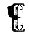
- Figure 6 describes in a cross-section the plug plugged into the socket.
- the body of the plug (26) closes and wraps the socket from three sides, preventing any possibility of a person touching the conductors.
- the points of contact between the conducting bodies of the socket and plug (34), (35), and (36) are at the ends of the slots in the socket.
- the special contour and construction at the socket sides for the connection with the plugs is at 90 degree angles between the body of the plug and the slots of the socket which creates a strong hold between the plug and socket.
- FIG 7 describes from an overview the socket where several plugs can be connected.
- plugs (37), (38) and (39) that are connected to one socket are exemplified.
- the socket is closed by two covers (40) and (41) at the two ends to prevent contact with the conductors.
- the plugs are inserted to the socket through the exit and entrance "station” of the plugs (8).
- the socket can be longer and accommodate more plugs. It is also possible to build a long socket with several "stations" or to join several sockets one to another.
- An advantage of this invention is that the width of plugs can be determined by the electric load of the appliance and be proportional to the amount of its current consumption.
- Figure 8 describes through isometrics the possibility of connecting two sockets one to another.
- the preferred possibility is closure through screws, that pass in the holes (42) at the edges of the conductors that are laid one above the other on adjacent sockets.
- the area of connection may be closed through a plastic cover.
- the invention that has been described, describes a plug and socket also with the conductor connected to the ground.
- the device may also work without grounding as is accepted in certain countries.
- the unique plug and socket according to the present invention can also operate in conjunction with the standard known plugs and sockets. If a standard socket already exists in the wall the socket, according to the invention, can be modified and may also have protruding pins exactly as in the standard plug. If a standard plug is to be used, the socket, according to the invention, may be modified by an addition of the standard two or three holes.
Landscapes
- Connector Housings Or Holding Contact Members (AREA)
- Medicines That Contain Protein Lipid Enzymes And Other Medicines (AREA)
Applications Claiming Priority (2)
| Application Number | Priority Date | Filing Date | Title |
|---|---|---|---|
| IL10461893 | 1993-02-04 | ||
| IL10461893A IL104618A (en) | 1993-02-04 | 1993-02-04 | Contact rail and adapter |
Publications (2)
| Publication Number | Publication Date |
|---|---|
| EP0609862A2 true EP0609862A2 (de) | 1994-08-10 |
| EP0609862A3 EP0609862A3 (de) | 1995-03-15 |
Family
ID=11064493
Family Applications (1)
| Application Number | Title | Priority Date | Filing Date |
|---|---|---|---|
| EP94101560A Withdrawn EP0609862A3 (de) | 1993-02-04 | 1994-02-02 | Stromschiene und Adapter. |
Country Status (7)
| Country | Link |
|---|---|
| US (1) | US5645437A (de) |
| EP (1) | EP0609862A3 (de) |
| JP (1) | JPH06318487A (de) |
| CN (1) | CN1100844A (de) |
| CA (1) | CA2114882A1 (de) |
| IL (1) | IL104618A (de) |
| PH (1) | PH31146A (de) |
Cited By (4)
| Publication number | Priority date | Publication date | Assignee | Title |
|---|---|---|---|---|
| DE29518253U1 (de) * | 1995-11-17 | 1996-01-11 | Briloner Leuchten GmbH, 59929 Brilon | Niedervoltstromschienensystem für Leuchten |
| DE10149889A1 (de) * | 2001-10-10 | 2003-05-08 | Ralf Wieduwilt | Niederspannungs-Verteilungssystem |
| US7575851B2 (en) | 2004-06-28 | 2009-08-18 | Canon Kabushiki Kaisha | Cationic photopolymerizable epoxy resin composition, minute structural member using the same and method for manufacturing minute structural member |
| CN112136253A (zh) * | 2018-05-16 | 2020-12-25 | 昕诺飞控股有限公司 | 轨道和插头的部件套件 |
Families Citing this family (7)
| Publication number | Priority date | Publication date | Assignee | Title |
|---|---|---|---|---|
| US6234851B1 (en) | 1999-11-09 | 2001-05-22 | General Electric Company | Stab connector assembly |
| US6439947B1 (en) | 2001-02-12 | 2002-08-27 | Tali Lehavi | Marking system and method for toys and similar objects |
| FR2860095B1 (fr) * | 2003-09-24 | 2006-03-10 | Eaton S A | Barre de raccordement electrique et dispositif de connexion adapte |
| US7114968B2 (en) * | 2004-10-27 | 2006-10-03 | Rafael Healy | Plastic gate for electrical outlets |
| US20100175919A1 (en) * | 2009-01-14 | 2010-07-15 | Boston Retail Products, Inc. | System and method for distribution of electrical power |
| CN102324672A (zh) * | 2011-08-01 | 2012-01-18 | 江苏六和新能源设备科技有限公司 | 电力通讯分配装置 |
| DE102013100435A1 (de) * | 2013-01-16 | 2014-07-17 | Conductix-Wampfler Gmbh | Verbindungselement für eine Schleifleitung, Schleifleitung und Verfahren zur Herstellung einer Schleifleitung |
Citations (4)
| Publication number | Priority date | Publication date | Assignee | Title |
|---|---|---|---|---|
| EP0147106A2 (de) * | 1983-12-09 | 1985-07-03 | National Service Industries, Inc. | Schienensystem mit elektrischer Energie |
| EP0159078A1 (de) * | 1984-04-02 | 1985-10-23 | Koninklijke Philips Electronics N.V. | Vorrichtung zur Stromentnahme an einer Spannungsschiene |
| US4861273A (en) * | 1987-10-13 | 1989-08-29 | Thomas Industries, Inc. | Low-voltage miniature track lighting system |
| DE4013863A1 (de) * | 1990-04-30 | 1991-10-31 | Staff Gmbh & Co Kg | Adapter fuer stromschienen |
Family Cites Families (10)
| Publication number | Priority date | Publication date | Assignee | Title |
|---|---|---|---|---|
| US2186601A (en) * | 1938-05-13 | 1940-01-09 | William F Borkenstein | Electric outlet fixture and extension cord therefor |
| US2227123A (en) * | 1938-09-12 | 1940-12-31 | Victor H Christen | Electric connection and the like |
| US2437579A (en) * | 1945-12-08 | 1948-03-09 | Robert E Wilson | Electrical outlet construction |
| CH482329A (de) * | 1968-12-06 | 1969-11-30 | Oskar Woertz Inh H & O Woertz | Elektrische Installationseinrichtung mit mindestens einer Stromführungsschiene |
| FR2255727A2 (en) * | 1973-12-19 | 1975-07-18 | Weidel Marie | Connector block movable along conduit - has rotary cam connecting contacts and operating block locking spring |
| US4173382A (en) * | 1977-01-27 | 1979-11-06 | Booty Donald J | Portable track lighting |
| US4773869A (en) * | 1986-04-03 | 1988-09-27 | Smart Nancy M | Electric wall unit |
| US4790766A (en) * | 1987-04-01 | 1988-12-13 | Booty Sr Donald J | Electrical power track system |
| FR2622747B1 (fr) * | 1987-11-04 | 1992-03-20 | Allers Christian | Baguette electrifiee faisant office de glissiere pour une prise electrique mobile |
| US4973796A (en) * | 1989-08-10 | 1990-11-27 | Visu-Wall By Hbsa Industries, Inc. | Electrified wall structure |
-
1993
- 1993-02-04 IL IL10461893A patent/IL104618A/xx not_active IP Right Cessation
-
1994
- 1994-02-02 EP EP94101560A patent/EP0609862A3/de not_active Withdrawn
- 1994-02-02 PH PH47700A patent/PH31146A/en unknown
- 1994-02-03 CA CA002114882A patent/CA2114882A1/en not_active Abandoned
- 1994-02-03 US US08/190,922 patent/US5645437A/en not_active Expired - Fee Related
- 1994-02-04 JP JP6031975A patent/JPH06318487A/ja active Pending
- 1994-02-04 CN CN94102747.3A patent/CN1100844A/zh active Pending
Patent Citations (4)
| Publication number | Priority date | Publication date | Assignee | Title |
|---|---|---|---|---|
| EP0147106A2 (de) * | 1983-12-09 | 1985-07-03 | National Service Industries, Inc. | Schienensystem mit elektrischer Energie |
| EP0159078A1 (de) * | 1984-04-02 | 1985-10-23 | Koninklijke Philips Electronics N.V. | Vorrichtung zur Stromentnahme an einer Spannungsschiene |
| US4861273A (en) * | 1987-10-13 | 1989-08-29 | Thomas Industries, Inc. | Low-voltage miniature track lighting system |
| DE4013863A1 (de) * | 1990-04-30 | 1991-10-31 | Staff Gmbh & Co Kg | Adapter fuer stromschienen |
Cited By (4)
| Publication number | Priority date | Publication date | Assignee | Title |
|---|---|---|---|---|
| DE29518253U1 (de) * | 1995-11-17 | 1996-01-11 | Briloner Leuchten GmbH, 59929 Brilon | Niedervoltstromschienensystem für Leuchten |
| DE10149889A1 (de) * | 2001-10-10 | 2003-05-08 | Ralf Wieduwilt | Niederspannungs-Verteilungssystem |
| US7575851B2 (en) | 2004-06-28 | 2009-08-18 | Canon Kabushiki Kaisha | Cationic photopolymerizable epoxy resin composition, minute structural member using the same and method for manufacturing minute structural member |
| CN112136253A (zh) * | 2018-05-16 | 2020-12-25 | 昕诺飞控股有限公司 | 轨道和插头的部件套件 |
Also Published As
| Publication number | Publication date |
|---|---|
| PH31146A (en) | 1998-03-20 |
| US5645437A (en) | 1997-07-08 |
| CA2114882A1 (en) | 1994-08-05 |
| JPH06318487A (ja) | 1994-11-15 |
| CN1100844A (zh) | 1995-03-29 |
| IL104618A0 (en) | 1993-06-10 |
| IL104618A (en) | 2000-10-31 |
| EP0609862A3 (de) | 1995-03-15 |
Similar Documents
| Publication | Publication Date | Title |
|---|---|---|
| US7128585B2 (en) | Elongated electrical outlet | |
| CA1202394A (en) | Adaptive strain relief for wiring devices | |
| US4445739A (en) | Male plug with automatic prong cover | |
| US4245880A (en) | Convenience outlet | |
| US5645437A (en) | Device of a plug and socket | |
| US4367370A (en) | Power panel system with selective multiple circuits | |
| US5788517A (en) | Cordless extension system | |
| US3382355A (en) | Illuminated electrical connector | |
| US7114968B2 (en) | Plastic gate for electrical outlets | |
| US3496518A (en) | Electrical power distribution systems | |
| US4013330A (en) | Dual-standard electric plug | |
| US5833357A (en) | Trouble light | |
| US5035646A (en) | Flush mounted receptacle and plug with pin and sleeve type contacts | |
| CA1211179A (en) | Electrical receptacle | |
| GB2203296A (en) | Plug arrangement | |
| CN100508284C (zh) | 用于不连续导体电连接的装置 | |
| FR2412182A1 (fr) | Socle d'enfichage pour cable de raccordement electrique | |
| GB2229588A (en) | Electrical connector | |
| US5595491A (en) | 240 volt receptacle module for modular electrical system | |
| GB2237455A (en) | Branching electric connector | |
| GB2318692A (en) | Electrical power supply plug/adaptor | |
| EP0465098B1 (de) | Speisegerät für eine Kabelkanaleinrichtung | |
| US6935884B1 (en) | Electrical connector | |
| CA1231406A (en) | Male plug with automatic prong cover | |
| US4726784A (en) | Connector for terminal free cable |
Legal Events
| Date | Code | Title | Description |
|---|---|---|---|
| PUAI | Public reference made under article 153(3) epc to a published international application that has entered the european phase |
Free format text: ORIGINAL CODE: 0009012 |
|
| AK | Designated contracting states |
Kind code of ref document: A2 Designated state(s): AT BE CH DE DK ES FR GB GR IE IT LI LU MC NL PT SE |
|
| PUAL | Search report despatched |
Free format text: ORIGINAL CODE: 0009013 |
|
| AK | Designated contracting states |
Kind code of ref document: A3 Designated state(s): AT BE CH DE DK ES FR GB GR IE IT LI LU MC NL PT SE |
|
| 17P | Request for examination filed |
Effective date: 19950608 |
|
| 17Q | First examination report despatched |
Effective date: 19970421 |
|
| GRAG | Despatch of communication of intention to grant |
Free format text: ORIGINAL CODE: EPIDOS AGRA |
|
| GRAG | Despatch of communication of intention to grant |
Free format text: ORIGINAL CODE: EPIDOS AGRA |
|
| GRAH | Despatch of communication of intention to grant a patent |
Free format text: ORIGINAL CODE: EPIDOS IGRA |
|
| STAA | Information on the status of an ep patent application or granted ep patent |
Free format text: STATUS: THE APPLICATION IS DEEMED TO BE WITHDRAWN |
|
| 18D | Application deemed to be withdrawn |
Effective date: 19990717 |