EP0609872A1 - Méthode et dispositif pour la consolidation en profondeur du sol - Google Patents
Méthode et dispositif pour la consolidation en profondeur du sol Download PDFInfo
- Publication number
- EP0609872A1 EP0609872A1 EP94101607A EP94101607A EP0609872A1 EP 0609872 A1 EP0609872 A1 EP 0609872A1 EP 94101607 A EP94101607 A EP 94101607A EP 94101607 A EP94101607 A EP 94101607A EP 0609872 A1 EP0609872 A1 EP 0609872A1
- Authority
- EP
- European Patent Office
- Prior art keywords
- trench
- soil
- excavated
- excavation
- support elements
- Prior art date
- Legal status (The legal status is an assumption and is not a legal conclusion. Google has not performed a legal analysis and makes no representation as to the accuracy of the status listed.)
- Granted
Links
- 239000002689 soil Substances 0.000 title claims abstract description 71
- 238000000034 method Methods 0.000 title claims abstract description 28
- 238000007596 consolidation process Methods 0.000 title claims abstract description 11
- 239000000463 material Substances 0.000 claims abstract description 46
- 238000009412 basement excavation Methods 0.000 claims abstract description 25
- 238000002360 preparation method Methods 0.000 claims abstract description 16
- 238000011049 filling Methods 0.000 claims abstract description 4
- 230000002250 progressing effect Effects 0.000 claims description 8
- 238000007711 solidification Methods 0.000 claims description 8
- 230000008023 solidification Effects 0.000 claims description 8
- 230000000750 progressive effect Effects 0.000 claims description 7
- 238000002156 mixing Methods 0.000 claims description 4
- 239000000126 substance Substances 0.000 claims description 4
- 235000008733 Citrus aurantifolia Nutrition 0.000 claims description 3
- 235000011941 Tilia x europaea Nutrition 0.000 claims description 3
- 239000004568 cement Substances 0.000 claims description 3
- 239000004571 lime Substances 0.000 claims description 3
- XLYOFNOQVPJJNP-UHFFFAOYSA-N water Substances O XLYOFNOQVPJJNP-UHFFFAOYSA-N 0.000 claims description 3
- 238000005056 compaction Methods 0.000 claims description 2
- 229910052500 inorganic mineral Inorganic materials 0.000 claims description 2
- 239000011707 mineral Substances 0.000 claims description 2
- 239000011150 reinforced concrete Substances 0.000 claims description 2
- 230000033764 rhythmic process Effects 0.000 claims description 2
- 238000005406 washing Methods 0.000 claims description 2
- 230000003014 reinforcing effect Effects 0.000 claims 1
- 230000006641 stabilisation Effects 0.000 claims 1
- 238000011105 stabilization Methods 0.000 claims 1
- 230000000087 stabilizing effect Effects 0.000 claims 1
- 238000005202 decontamination Methods 0.000 description 3
- 239000000654 additive Substances 0.000 description 2
- 239000002585 base Substances 0.000 description 2
- 230000003588 decontaminative effect Effects 0.000 description 2
- 238000006073 displacement reaction Methods 0.000 description 2
- 239000003637 basic solution Substances 0.000 description 1
- 230000006835 compression Effects 0.000 description 1
- 238000007906 compression Methods 0.000 description 1
- 239000004567 concrete Substances 0.000 description 1
- 238000011109 contamination Methods 0.000 description 1
- 230000000694 effects Effects 0.000 description 1
- 230000002349 favourable effect Effects 0.000 description 1
- 230000003993 interaction Effects 0.000 description 1
- 238000011068 loading method Methods 0.000 description 1
- 230000001681 protective effect Effects 0.000 description 1
- 238000000746 purification Methods 0.000 description 1
- 239000000243 solution Substances 0.000 description 1
Images

Classifications
-
- E—FIXED CONSTRUCTIONS
- E02—HYDRAULIC ENGINEERING; FOUNDATIONS; SOIL SHIFTING
- E02D—FOUNDATIONS; EXCAVATIONS; EMBANKMENTS; UNDERGROUND OR UNDERWATER STRUCTURES
- E02D17/00—Excavations; Bordering of excavations; Making embankments
- E02D17/06—Foundation trenches ditches or narrow shafts
- E02D17/08—Bordering or stiffening the sides of ditches trenches or narrow shafts for foundations
- E02D17/086—Travelling trench shores
Definitions
- the invention relates to a method for deep ground consolidation, in particular for consolidating the underground of railroad track bodies, according to the preamble of claim 1 and a device for performing this method.
- a disadvantage of these known methods is that time and energy must be expended in order to drive away the excavation or to move the material to be filled in from a remote location to the excavation site for refilling. Landfill space is also required for the excavation to be driven, which is often difficult to find today.
- the problem with which the present invention is concerned is to provide a better, in particular resource-saving and energy-saving and thus overall more environmentally friendly solution.
- Shredding of the excavated soil before mixing is necessary if the excavated soil contains soil classes 4 to 7 according to DIN 18300. It is possible to classify the excavated soil before crushing according to soil classes that require crushing and those that do not require crushing.
- both the excavated soil and the aggregates are mixed in a correspondingly coordinated dosage, for which purpose the individual substances are added in metered form to the mixer in question .
- the aggregates to be used for solidification are to the person skilled in the art with reference to the one to be processed in each case
- Soil and the solidification to be achieved in the result are known per se and can be of a mineral, hydraulic and / or chemical type.
- lime and / or cement with optionally water can be used as additives.
- a thermal, chemical, biological or washing decontamination can be integrated into the on-site soil preparation.
- the methods to be used for this purpose are also known per se to the person skilled in the art, so that this need not be explained in more detail here.
- Which of the above-mentioned decontamination processes is to be used in individual cases depends, of course, on the type of contamination in the excavated soil. In the case of a biological treatment, this can take place in that the additives which bring about the biological purification are only added during the treatment and their effect is only effective in the refilled soil material.
- a prerequisite for the method according to the invention is a continuously progressing trench, the length of which should be as short as possible so that the excavated soil can be refilled and compacted in the processed form in the shortest possible way.
- a short, open trench is particularly important and advantageous in cases in which the underground of a railroad track has to be carried out next to a neighboring track that is being used at a close distance. Because then with the open trench care must be taken to ensure that the subsurface of the track being driven does not penetrate into the open trench. In order to avoid this, the progressive trench must always be supported on the longitudinal side wall lying to the neighboring track in these cases.
- Such support can be achieved, for example, by introducing a supporting wall into the ground before excavating the trench, which later forms the side longitudinal wall lying to the neighboring track when the trench is excavated.
- a support wall can be introduced into the ground as a lost wall or it can also be designed in such a way that it can be removed after the trench has been refilled.
- a lost support wall can be achieved, for example, by using a tiller to mill a gap in the ground before digging the trench, which is then poured out with steel-reinforced concrete. This concrete wall can also be secured by tie rods against the subsurface of the neighboring track, next to which the trench is to be drawn along the supporting wall.
- Such a constant wandering of the support walls can be achieved in that in the longitudinal center of the trench laterally braced support elements are provided, with which a firm support can be achieved between the two side walls of the trench.
- the bracing of the support elements against the side walls of the trench is released and the support elements are drawn together.
- the entire unit of the support elements can be advanced or advanced in the direction of the trench.
- the pulling can be carried out, for example, with an excavator that is located outside the trench.
- the bracing is expediently carried out via hydraulic drives.
- the support elements can have movable shields in the direction of the trench progress. These shields can be moved between two predefined end positions. In one end position, the shields are attracted to the supporting element that carries them. The shields are brought into this end position when the support elements are moved in a mutually relaxed position in the direction of the trench progression. As soon as the support elements are then braced again against the longitudinal side walls of the trench, the shields are brought into their second end position, being pressed into the soil to be excavated. The shields are pressed in because the support elements have been advanced so far in the direction of the trench that the shields, in their position in relation to the support elements, have come to rest directly on the soil still to be excavated. The displacement of the shields relative to the support elements is also advantageously carried out hydraulically.
- the front edge of the shields can be inclined according to the slope angle that results from excavating the soil material.
- Corresponding shields can also be attached to the support elements at the end opposite the direction of progression of the trench in the same way.
- the trench roller can be attached to the boom of a telescopic excavator be guided, which is supported on the already refilled and compacted soil.
- a telescopic excavator is also particularly suitable for excavating soil.
- a device suitable for carrying out the method according to the invention must consist of mobile units which can follow the continuously progressing trench at about the same time and can each be assigned to the trench opening in such a way that, on the one hand, the excavation can be carried out directly by the excavation device and, on the other hand, the processed soil material also can be returned directly to the trench filling area.
- the width of the aggregates required for preparing the excavated soil does not at least substantially exceed the width of the trench. This is usually necessary, for example, if the surface of a track body is to be prepared, which is in the immediate vicinity of a parallel railroad track that should also be passable during the preparation time.
- the method according to the invention can be carried out particularly successfully and economically with a device in which the essential aggregates required for the preparation of the excavation work are stored mobile above the opening of the progressive trench.
- the mobile unit with the aggregates required for soil preparation it is also possible for the mobile unit with the aggregates required for soil preparation to be stored in a mobile manner on the already filled soil material.
- the length of the progressing trench be particularly short. In some cases, this avoids side support of the open trench.
- the wandering hydraulic support device described above can also be used here.
- this support frame can be applied to a slide, the runners of which are supported on the longitudinal ends of the trench.
- the sledge can then be pushed in a simple manner as the digging progresses following the digging. The pushing can be carried out, for example, by the excavator carrying out the excavation by simply pulling.
- the supporting structure can also be supported on the ground outside the open trench by means of wheels.
- a conveyor belt can be built into the supporting structure, via which the prepared soil material can be distributed in a targeted manner.
- the conveyor belt can be swiveled horizontally in order to be able to distribute the soil material to be refilled evenly over the width of the trench.
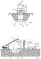
- a trench 1 which progressively migrates in the direction of arrow A, it becomes at the front in the direction of progress lying end 2 excavated soil material and refilled in prepared form at the opposite end.
- the depth of the trench shown is approximately two to three meters, although greater depths can also be present.
- the length of the trench 1 is about seven to eight meters at its base.
- the longitudinal extent of the trench 1 on the surface measures approximately fifteen meters.
- the soil preparation plant is supported on a carriage 4 which is supported on the end edges of the trench 1 and on which the individual treatment units are mounted on a support frame 5 above the opening of the trench 1.
- the individual processing units consist of a material feed hopper 6, which receives the soil material excavated from the bucket of a telescopic excavator 7 and transfers it to a crusher-mixer unit 8 that fulfills the functions of a crusher and mixer.
- the processed soil material falls from the crusher-mixer unit 8 onto a conveyor belt 9, which leads this material to the rear end of the trench 1 as refill material. So that the material from the conveyor belt can be distributed evenly over the width of the trench, the conveyor belt 9 is pivoted accordingly.
- the refilled, prepared soil material is compacted in layers in the region of the rear end of the trench 1 using a trench roller 10.
- This trench roller 10 is guided by the extension arm of a telescopic excavator 11 which is supported on the refilled soil material.
- the trench roller 10 is covered at the top by a protective roof 12.
- aggregates such as cement, lime and / or water have to be added for the necessary consolidation of the soil material during processing
- these aggregates can be fed from a container 13 via a screw conveyor 14 into the hopper 6 for the excavated material to be abandoned .
- support elements 15 are articulated on the supporting structure 5.
- the support elements 15 extend essentially over the area in the longitudinal center of the trench 1, which is located between the actual excavation area at the front end 2 and the refill area at the rear end 3 of the trench.
- the plate-shaped support elements 15 in the present case are adapted in shape to the angle of repose of the front end 2 of the trench 1, i. H. there they have an inclined leading edge.
- longitudinally displaceable shields 16 are arranged in them.
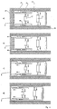
- the support elements 15 can be displaced transversely to the longitudinal direction of the trench 1 via hydraulic drives.
- the support elements 15 are firmly clamped against the trench side walls by the hydraulic drives 17. This bracing was preceded by a displacement of the support elements 15 in the direction of the trench progression.
- the shields 16 hinged to these elements are in the state in which they are retracted relative to these elements.
- the shields 16 can be driven in the direction of the trench progression by means of the hydraulic drives 18 provided for this purpose, namely into the soil which has not yet been excavated.
- the extended state of the shields 16 is shown in FIG. 4b.
- FIG. 4c shows the state in which the support elements 15 have been pulled off the trench side walls by the hydraulic drives 17.
- the shields 16 are in a position extended to the support elements 15.
- the support elements 15 can be moved in the direction of the trench by advancing the slide 4.
- a correspondingly shifted position of the support elements 15 is shown in FIG. 4d.
- the shields 16, which were initially brought into contact with the ground up to the open front edge, are brought into this ground with the aid of the hydraulic drives 18 driven in.
- the support elements have 15 also in the front area a direct support within the ground.
- the entire unit of the mobile processing plant is located on the edge region of the progressing trench 1 which has already been filled up again.
- the direction of the trench progress is again indicated by an arrow A.
- the mobile processing plant consists of two conveyor belts 19 and 20 arranged one above the other.
- the upper of these conveyor belts is the conveyor belt 19 onto which the excavation of the soil from the bucket of a telescopic excavator 7 is carried out at the end facing the trench 1.
- the excavated soil reaches a crusher-mixer unit 22 via a funnel 21.
- a conveyor belt 20 running below the conveyor belt 19 conveys the processed soil material to the rear end 3 of the trench 1 for subsequent compaction .
- aggregates can also be added to the soil material to be treated via additional devices.
- the progressive trench can have a particularly short length. In this way it is possible in many cases to be able to do without a lateral support of the trench 1. In principle, however, progressively movable support elements 15 can of course also be used in this embodiment.
Landscapes
- Engineering & Computer Science (AREA)
- Mining & Mineral Resources (AREA)
- General Engineering & Computer Science (AREA)
- General Life Sciences & Earth Sciences (AREA)
- Paleontology (AREA)
- Civil Engineering (AREA)
- Life Sciences & Earth Sciences (AREA)
- Structural Engineering (AREA)
- Consolidation Of Soil By Introduction Of Solidifying Substances Into Soil (AREA)
- Soil Working Implements (AREA)
- Cultivation Of Plants (AREA)
- Bulkheads Adapted To Foundation Construction (AREA)
- Processing Of Solid Wastes (AREA)
Applications Claiming Priority (2)
| Application Number | Priority Date | Filing Date | Title |
|---|---|---|---|
| DE4303285 | 1993-02-05 | ||
| DE4303285A DE4303285A1 (de) | 1993-02-05 | 1993-02-05 | Verfahren zur tiefgründigen Bodenverfestigung und Einrichtung zur Durchführung |
Publications (2)
| Publication Number | Publication Date |
|---|---|
| EP0609872A1 true EP0609872A1 (fr) | 1994-08-10 |
| EP0609872B1 EP0609872B1 (fr) | 1997-07-09 |
Family
ID=6479685
Family Applications (1)
| Application Number | Title | Priority Date | Filing Date |
|---|---|---|---|
| EP94101607A Expired - Lifetime EP0609872B1 (fr) | 1993-02-05 | 1994-02-03 | Méthode et dispositif pour la consolidation en profondeur du sol |
Country Status (3)
| Country | Link |
|---|---|
| EP (1) | EP0609872B1 (fr) |
| AT (1) | ATE155187T1 (fr) |
| DE (2) | DE4303285A1 (fr) |
Cited By (1)
| Publication number | Priority date | Publication date | Assignee | Title |
|---|---|---|---|---|
| FR2972042A1 (fr) * | 2011-02-25 | 2012-08-31 | Atlantique Travaux Publics | Equipement pour distribuer des materiaux en fond de tranchee ouverte, pour constituer un lit de pose. |
Families Citing this family (12)
| Publication number | Priority date | Publication date | Assignee | Title |
|---|---|---|---|---|
| DE4409507A1 (de) * | 1994-03-19 | 1995-09-21 | Walter Schoelkopf | Vorrichtung zur Aufbereitung von Erdreich zu einem standfesten Baumaterial |
| DE19547589A1 (de) * | 1995-12-20 | 1997-06-26 | Bauer Spezialtiefbau | Schneckenpfähle mit Bodenmörtel |
| DE19650443A1 (de) * | 1996-01-25 | 1997-07-31 | Weiss Gmbh & Co Leonhard | Mobile Aufbereitungseinrichtung für Bodenaushub bei einem Bahngleis |
| EP0786558A1 (fr) | 1996-01-25 | 1997-07-30 | LEONHARD WEISS GmbH & Co. NIEDERLASSUNG CRAILSHEIM | Appareillage mobile le reconditionnement de déblais d'une voie ferrée |
| DE19623454C2 (de) * | 1996-06-12 | 2000-06-29 | Hartung Bau Gmbh & Co Kg | Verfahren zum Herstellen und Verbauen von Gräben |
| DE19625590C2 (de) * | 1996-06-27 | 2000-06-08 | Suilmann Tiefbau Gmbh & Co Kg | Einrichtung zum Verfüllen von Baugruben, Rohrgräben, Kabelgräben oder dgl. |
| DE19627465C2 (de) * | 1996-07-08 | 1997-08-07 | Uhrig Strasen Und Tiefbau Gmbh | Verfahren zum Aufbereiten von Aushubmaterial |
| DE29701741U1 (de) * | 1997-02-01 | 1997-05-15 | Bauer Spezialtiefbau Gmbh, 86529 Schrobenhausen | Mobile Anlage zur Aufbereitung von gegreifertem Schlitzwandaushub |
| DE19718330A1 (de) * | 1997-04-30 | 1998-11-19 | Weiss Gmbh & Co Leonhard | Verwendung einer mit einer Grabenaushubeinrichtung zusammenarbeitenden, mobilen Aufbereitungseinrichtung für Bodenaushub im Straßenbau |
| DE19733664A1 (de) * | 1997-08-04 | 1999-02-11 | Weiss Gmbh & Co Leonhard | Verwendung einer Grabenaushub- und Aufbereitungseinrichtung zur Sanierung und/oder Strukturverbesserung von Wasserschutzdämmen |
| DE10111305B4 (de) * | 2000-11-30 | 2006-07-27 | Schenk, Jürgen | Vorrichtung und Verfahren zum Aufbereiten von Material, insbesondere mineralischem Material wie Bodenaushub |
| DE102017118777B4 (de) * | 2017-08-17 | 2019-07-25 | Hartmut Fritsche | Verbauvorrichtung für Gräben oder grabenähnliche Bauwerke |
Citations (5)
| Publication number | Priority date | Publication date | Assignee | Title |
|---|---|---|---|---|
| BE793936A (fr) * | 1973-01-12 | 1973-05-02 | Brecht Heinz | Procede et dispositif pour le coffrage et la remise en etat de tranchees pour canalisations |
| CH582282A5 (en) * | 1975-02-24 | 1976-11-30 | Gysel & Meier Hoch Und Tiefbau | Progressive excavation and filling system for trenches - has inserted shoring walls with rear wall facilitating progressive filling |
| US4073410A (en) * | 1976-09-08 | 1978-02-14 | Melcher Herbert R | Construction filler material dispensing apparatus |
| EP0103706A1 (fr) * | 1982-09-17 | 1984-03-28 | Heinz Brecht | Dispositif de soutènement pour l'étayage de tranchées |
| DE9211801U1 (de) * | 1992-09-02 | 1992-11-05 | Josef Möbius Bau-Gesellschaft (GmbH & Co), 2000 Hamburg | Vorrichtung zum Austausch von Bodenmaterial, insbesondere neben Verkehrswegen und Bauwerken |
Family Cites Families (10)
| Publication number | Priority date | Publication date | Assignee | Title |
|---|---|---|---|---|
| US3290804A (en) * | 1964-04-03 | 1966-12-13 | Hanson Co R A | Consolidating apparatus |
| DE2135577C3 (de) * | 1971-07-16 | 1975-01-30 | Heinz 7526 Rheinsheim Brecht | Verbaukorb zum kontinuierlich fortschreitenden Verbau eines Kanalgrabens |
| DE2450281A1 (de) * | 1974-10-23 | 1976-04-29 | Hochtief Ag Hoch Tiefbauten | Vorrichtung zum fortschreitenden aushub und verbau offener baugraeben und verfahren dazu |
| DE2616970C3 (de) * | 1976-04-17 | 1985-02-21 | Wayss & Freytag Ag, 6000 Frankfurt | Verfahren und Abschalelement zur Herstellung einer Schlitzwand in Fertigteilverbundkonstruktion |
| DE2658349A1 (de) * | 1976-12-23 | 1978-06-29 | Gewerk Eisenhuette Westfalia | Verfahren und einrichtung zum vortrieb eines offenen grabens, insbesondere fuer die rohrverlegung im erdboden |
| DE3202916A1 (de) * | 1982-01-29 | 1983-08-11 | Brecht, Maria, 7522 Philippsburg | Verbaukorb zum verbau eines kanalgrabens |
| US4494694A (en) * | 1982-09-28 | 1985-01-22 | Iowa State University Research Foundation, Inc. | Support system for a railroad track |
| FR2608183B1 (fr) * | 1986-12-15 | 1989-04-28 | France Etat Ponts Chaussees | Procede et dispositif de mise en place sur une surface d'un sol renforce constitue d'elements particulaires et d'un liant |
| DE9013563U1 (de) * | 1990-08-10 | 1990-11-22 | Josef Möbius Bau-Gesellschaft (GmbH & Co), 2000 Hamburg | Vorrichtung zum Bodenaustausch, insbesondere neben Verkehrswegen und Bauwerken |
| DE4029632C2 (de) * | 1990-09-19 | 1995-06-01 | Westfalia Becorit Ind Tech | Abstützvorrichtung für eine offene, wandernde Baugrube |
-
1993
- 1993-02-05 DE DE4303285A patent/DE4303285A1/de not_active Withdrawn
-
1994
- 1994-02-03 DE DE59403267T patent/DE59403267D1/de not_active Expired - Fee Related
- 1994-02-03 EP EP94101607A patent/EP0609872B1/fr not_active Expired - Lifetime
- 1994-02-03 AT AT94101607T patent/ATE155187T1/de active
Patent Citations (5)
| Publication number | Priority date | Publication date | Assignee | Title |
|---|---|---|---|---|
| BE793936A (fr) * | 1973-01-12 | 1973-05-02 | Brecht Heinz | Procede et dispositif pour le coffrage et la remise en etat de tranchees pour canalisations |
| CH582282A5 (en) * | 1975-02-24 | 1976-11-30 | Gysel & Meier Hoch Und Tiefbau | Progressive excavation and filling system for trenches - has inserted shoring walls with rear wall facilitating progressive filling |
| US4073410A (en) * | 1976-09-08 | 1978-02-14 | Melcher Herbert R | Construction filler material dispensing apparatus |
| EP0103706A1 (fr) * | 1982-09-17 | 1984-03-28 | Heinz Brecht | Dispositif de soutènement pour l'étayage de tranchées |
| DE9211801U1 (de) * | 1992-09-02 | 1992-11-05 | Josef Möbius Bau-Gesellschaft (GmbH & Co), 2000 Hamburg | Vorrichtung zum Austausch von Bodenmaterial, insbesondere neben Verkehrswegen und Bauwerken |
Cited By (1)
| Publication number | Priority date | Publication date | Assignee | Title |
|---|---|---|---|---|
| FR2972042A1 (fr) * | 2011-02-25 | 2012-08-31 | Atlantique Travaux Publics | Equipement pour distribuer des materiaux en fond de tranchee ouverte, pour constituer un lit de pose. |
Also Published As
| Publication number | Publication date |
|---|---|
| DE4303285A1 (de) | 1994-08-11 |
| DE59403267D1 (de) | 1997-08-14 |
| EP0609872B1 (fr) | 1997-07-09 |
| ATE155187T1 (de) | 1997-07-15 |
Similar Documents
| Publication | Publication Date | Title |
|---|---|---|
| EP0609872B1 (fr) | Méthode et dispositif pour la consolidation en profondeur du sol | |
| DE4329208A1 (de) | Vielseitiges Verfahren und Vorrichtung zum Boden-Verstärken und -Verdichten | |
| DE4029632A1 (de) | Abstuetzvorrichtung fuer eine offene, wandernde baugrube | |
| DE3439858A1 (de) | Verfahren und vorrichtung zur abdichtung unterirdischer bodenmassen, insbesondere zur nachtraeglichen behandlung von deponien o.dgl. | |
| AT516837A4 (de) | Verfahren zur Bankettstabilisierung und Einrichtung zur Durchführung desselben | |
| DE2246125A1 (de) | Schalungsvorrichtung zur packung von grubenabraummaterial | |
| EP0509385B1 (fr) | Procédé pour la fabrication de corps en béton et de corps en ciment dans le sol | |
| EP0585657B1 (fr) | Procédé et dispositif pour le remplacement du sol, particulièrement à proximité de routes et de bâtiments | |
| DE1534383B1 (de) | Verfahren zur Herstellung tragfaehiger Grabenverfuellungen nach Aufgrabungen in Verkehrswegen unter Verwendung einer fahrbaren Vorrichtung | |
| DE4206994C2 (de) | Verfahren und Vorrichtung zur Stabilisierung beschädigter Straßendecken | |
| DE3605062A1 (de) | Abdichtung von deponien | |
| DE19542031B4 (de) | Bodenverfestigungsvorrichtung | |
| CH474618A (de) | Verfahren zum Reinigen, Nivellieren und Verdichten des Schotters von Gleisbettungen und gleichzeitigem Stabilisieren des Erdplanums bei liegendem Gleis, sowie Maschine zur Durchführung des Verfahrens | |
| DD154226A5 (de) | Verfahren und vorrichtung zur untergrundsarnierung von eisenbahngleisen | |
| DE3009923A1 (de) | Verfahren und einrichtung zum abbau der pfeiler beim kammer-pfeilerbau | |
| DE69406988T2 (de) | Vorrichtung und Verfahren zur Herstellung von monolithischen Schlitzwänden oder dergleichen | |
| DE2543997C2 (de) | Verfahren zum Durchpressen eines insbesondere rohrförmigen Baukörpers in einen Erddamm o.dgl. | |
| DE60000529T2 (de) | Verfahren und Vorrichtung zur Behandlung von Materialien hauptsächlich bestehend aus feuchtem Ton, insbesondere Bodenaushub | |
| DE19547589A1 (de) | Schneckenpfähle mit Bodenmörtel | |
| EP0233979B1 (fr) | Etanchement de décharges | |
| DE4136610C2 (de) | Verfahren zum Verbreitern eines Fahrweges, insbesondere eines Wasserweges | |
| DE19619532C2 (de) | Verfahren zur Herstellung einer begehbarer Tunnelverbindung zwischen zwei benachbarten, verbohrten Schachtbohrungen und Vorrichtung zur Durchführung des Verfahrens | |
| DE19536778C1 (de) | Maschine zum Einbauen einer im wesentlichen senkrechten Dichtung in eine Bodenformation | |
| DE3545207A1 (de) | Verfahren und vorrichtung zum einbringen einer wasserundurchlaessigen schicht ins erdreich | |
| DE10207126A1 (de) | Grabenfräse |
Legal Events
| Date | Code | Title | Description |
|---|---|---|---|
| PUAI | Public reference made under article 153(3) epc to a published international application that has entered the european phase |
Free format text: ORIGINAL CODE: 0009012 |
|
| AK | Designated contracting states |
Kind code of ref document: A1 Designated state(s): AT BE CH DE FR LI NL |
|
| 17P | Request for examination filed |
Effective date: 19940802 |
|
| 17Q | First examination report despatched |
Effective date: 19960619 |
|
| GRAG | Despatch of communication of intention to grant |
Free format text: ORIGINAL CODE: EPIDOS AGRA |
|
| GRAH | Despatch of communication of intention to grant a patent |
Free format text: ORIGINAL CODE: EPIDOS IGRA |
|
| GRAH | Despatch of communication of intention to grant a patent |
Free format text: ORIGINAL CODE: EPIDOS IGRA |
|
| GRAA | (expected) grant |
Free format text: ORIGINAL CODE: 0009210 |
|
| AK | Designated contracting states |
Kind code of ref document: B1 Designated state(s): AT BE CH DE FR LI NL |
|
| REF | Corresponds to: |
Ref document number: 155187 Country of ref document: AT Date of ref document: 19970715 Kind code of ref document: T |
|
| REG | Reference to a national code |
Ref country code: CH Ref legal event code: EP |
|
| REF | Corresponds to: |
Ref document number: 59403267 Country of ref document: DE Date of ref document: 19970814 |
|
| ET | Fr: translation filed | ||
| PLBE | No opposition filed within time limit |
Free format text: ORIGINAL CODE: 0009261 |
|
| STAA | Information on the status of an ep patent application or granted ep patent |
Free format text: STATUS: NO OPPOSITION FILED WITHIN TIME LIMIT |
|
| 26N | No opposition filed | ||
| PGFP | Annual fee paid to national office [announced via postgrant information from national office to epo] |
Ref country code: FR Payment date: 19990215 Year of fee payment: 6 |
|
| PGFP | Annual fee paid to national office [announced via postgrant information from national office to epo] |
Ref country code: AT Payment date: 19990219 Year of fee payment: 6 Ref country code: BE Payment date: 19990219 Year of fee payment: 6 |
|
| PGFP | Annual fee paid to national office [announced via postgrant information from national office to epo] |
Ref country code: NL Payment date: 19990228 Year of fee payment: 6 |
|
| PGFP | Annual fee paid to national office [announced via postgrant information from national office to epo] |
Ref country code: CH Payment date: 19990304 Year of fee payment: 6 |
|
| PG25 | Lapsed in a contracting state [announced via postgrant information from national office to epo] |
Ref country code: AT Free format text: LAPSE BECAUSE OF NON-PAYMENT OF DUE FEES Effective date: 20000203 |
|
| PGFP | Annual fee paid to national office [announced via postgrant information from national office to epo] |
Ref country code: DE Payment date: 20000210 Year of fee payment: 7 |
|
| PG25 | Lapsed in a contracting state [announced via postgrant information from national office to epo] |
Ref country code: BE Free format text: LAPSE BECAUSE OF NON-PAYMENT OF DUE FEES Effective date: 20000228 |
|
| PG25 | Lapsed in a contracting state [announced via postgrant information from national office to epo] |
Ref country code: LI Free format text: LAPSE BECAUSE OF NON-PAYMENT OF DUE FEES Effective date: 20000229 Ref country code: CH Free format text: LAPSE BECAUSE OF NON-PAYMENT OF DUE FEES Effective date: 20000229 |
|
| BERE | Be: lapsed |
Owner name: LEONHARD WEISS G.M.B.H. & CO. NIEDERLASSUNG CRAIL Effective date: 20000228 |
|
| PG25 | Lapsed in a contracting state [announced via postgrant information from national office to epo] |
Ref country code: NL Free format text: LAPSE BECAUSE OF NON-PAYMENT OF DUE FEES Effective date: 20000901 |
|
| REG | Reference to a national code |
Ref country code: CH Ref legal event code: PL |
|
| PG25 | Lapsed in a contracting state [announced via postgrant information from national office to epo] |
Ref country code: FR Free format text: LAPSE BECAUSE OF NON-PAYMENT OF DUE FEES Effective date: 20001031 |
|
| NLV4 | Nl: lapsed or anulled due to non-payment of the annual fee |
Effective date: 20000901 |
|
| REG | Reference to a national code |
Ref country code: FR Ref legal event code: ST |
|
| PG25 | Lapsed in a contracting state [announced via postgrant information from national office to epo] |
Ref country code: DE Free format text: LAPSE BECAUSE OF NON-PAYMENT OF DUE FEES Effective date: 20011201 |