EP0609948A1 - Caméra ayant une fonction de poursuite de cible - Google Patents
Caméra ayant une fonction de poursuite de cible Download PDFInfo
- Publication number
- EP0609948A1 EP0609948A1 EP94200265A EP94200265A EP0609948A1 EP 0609948 A1 EP0609948 A1 EP 0609948A1 EP 94200265 A EP94200265 A EP 94200265A EP 94200265 A EP94200265 A EP 94200265A EP 0609948 A1 EP0609948 A1 EP 0609948A1
- Authority
- EP
- European Patent Office
- Prior art keywords
- follow
- photographed
- camera
- target
- photometric
- Prior art date
- Legal status (The legal status is an assumption and is not a legal conclusion. Google has not performed a legal analysis and makes no representation as to the accuracy of the status listed.)
- Ceased
Links
Images





Classifications
-
- G—PHYSICS
- G01—MEASURING; TESTING
- G01S—RADIO DIRECTION-FINDING; RADIO NAVIGATION; DETERMINING DISTANCE OR VELOCITY BY USE OF RADIO WAVES; LOCATING OR PRESENCE-DETECTING BY USE OF THE REFLECTION OR RERADIATION OF RADIO WAVES; ANALOGOUS ARRANGEMENTS USING OTHER WAVES
- G01S3/00—Direction-finders for determining the direction from which infrasonic, sonic, ultrasonic or electromagnetic waves, or particle emission, not having a directional significance, are being received
- G01S3/78—Direction-finders for determining the direction from which infrasonic, sonic, ultrasonic or electromagnetic waves, or particle emission, not having a directional significance, are being received using electromagnetic waves other than radio waves
- G01S3/782—Systems for determining direction or deviation from predetermined direction
- G01S3/785—Systems for determining direction or deviation from predetermined direction using adjustment of orientation of directivity characteristics of a detector or detector system to give a desired condition of signal derived from that detector or detector system
- G01S3/786—Systems for determining direction or deviation from predetermined direction using adjustment of orientation of directivity characteristics of a detector or detector system to give a desired condition of signal derived from that detector or detector system the desired condition being maintained automatically
- G01S3/7864—T.V. type tracking systems
-
- H—ELECTRICITY
- H04—ELECTRIC COMMUNICATION TECHNIQUE
- H04N—PICTORIAL COMMUNICATION, e.g. TELEVISION
- H04N23/00—Cameras or camera modules comprising electronic image sensors; Control thereof
- H04N23/60—Control of cameras or camera modules
- H04N23/63—Control of cameras or camera modules by using electronic viewfinders
- H04N23/633—Control of cameras or camera modules by using electronic viewfinders for displaying additional information relating to control or operation of the camera
- H04N23/635—Region indicators; Field of view indicators
-
- H—ELECTRICITY
- H04—ELECTRIC COMMUNICATION TECHNIQUE
- H04N—PICTORIAL COMMUNICATION, e.g. TELEVISION
- H04N23/00—Cameras or camera modules comprising electronic image sensors; Control thereof
- H04N23/60—Control of cameras or camera modules
- H04N23/67—Focus control based on electronic image sensor signals
-
- H—ELECTRICITY
- H04—ELECTRIC COMMUNICATION TECHNIQUE
- H04N—PICTORIAL COMMUNICATION, e.g. TELEVISION
- H04N25/00—Circuitry of solid-state image sensors [SSIS]; Control thereof
- H04N25/10—Circuitry of solid-state image sensors [SSIS]; Control thereof for transforming different wavelengths into image signals
- H04N25/11—Arrangement of colour filter arrays [CFA]; Filter mosaics
Definitions
- the present invention relates to a camera, having a target follow up function, which automatically follows up a moving object to be photographed.
- an automatic follow up focus detection device As a device which automatically follows up an object to be photographed which is moving, and which performs focus detection and focus adjustment, an automatic follow up focus detection device is known (refer to U.S. Patent No.5,031,049).
- the overall construction of this device is shown in Fig. 8.
- a ray bundle from the object to be photographed which has passed through a photographic lens 20 is led to and focused upon an imaging element 21 which is made up from a plurality of charge accumulation type photoelectric conversion elements.
- the imaging element 21 outputs object to be photographed image signals which correspond to the distribution of light intensity in this image of the object to be photographed to a signal processing circuit 22 in time series.
- the signal processing circuit 22 converts these object to be photographed image signals into a video signal and outputs them, and at the same time outputs color difference signals (R-Y) and (B-Y) to a color detection circuit 23.
- This color detection circuit 23 detects color information relating to the object to be photographed, and a follow up circuit 24 records this detected color information as characteristic information of the object to be photographed. Further, this follow up circuit 24 compares this color information which is recorded as characteristic information of the object to be photographed and the color information newly detected by the color detection circuit 23, and based upon the result of this comparison determines whether or not movement of the object to be photographed has occurred. And, when the target object to be photographed has moved, the follow up circuit 24 moves the focus detection region to the position to which said target object has moved, and performs focus detection and focus adjustment.
- a single lens reflex camera is constructed so that a ray bundle from the object to be photographed which has passed through a photographic lens is reflected from a quick return mirror and is directed to the eyeball of the photographer via an optical system including a pentaprism or the like provided in the upper portion of the camera, it is necessary to provide the photometric element at a position after the light from the object to be photographed has passed through the pentaprism.
- the quick return mirror is raised and is removed from the light path between the photographic lens and the surface of the film at this time.
- the imaging element is provided at a position after the light from the object to be photographed has passed through the pentaprism, during the exposure process detection of an image of the object to be photographed by the imaging element is temporarily interrupted. As a result, if the object to be photographed continues to move during the exposure process as well, after the exposure has been completed the object to be photographed is lost sight of, and the problem arises that continued follow up becomes impossible.
- a correlation follow up device is per se known (refer to Japanese laid-open Application No. 56-86594) which performs correlation calculation between two sets of image data representing the object to be photographed which are detected at different time points by the imaging element, and which follows up the target object to be photographed within the visual field of the imaging element.
- this device there is no consideration of any measures to be taken when the target object to be photographed is lost sight of.
- the objective of the present invention is to provide a camera having the function of following up a target object to be photographed, which can continue the following up of the target object after the process of exposure has been completed without losing sight of it, even if the target object moves during exposure.
- the camera having a target follow up function comprises: a photometric means, which performs photometry on a plurality of regions into which the photographic field is divided, and which outputs information representing the brightness of each of said regions; a follow up means, which detects the movement of an object to be photographed based upon the brightness information output by said photometric means, and which follows up said object to be photographed; and a prediction means which, during the time period while said photometric means cannot perform photometry, predicts the movement of said object to be photographed based upon the movement information for said object to be photographed detected by said follow up means, and which obtains the position of said object to be photographed for when photometry by said photometric means recommences.
- Another objective of the present invention is to provide a camera having the function of following up a target object to be photographed, which, even when the object to be photographed is lost sight of while it is being followed up, performs an appropriate corresponding operation, so that the photographer can quickly proceed to the next action.
- the camera having a target follow up function comprises: a photometric means, which performs photometry on a plurality of regions into which the photographic field is divided, and which outputs information representing the brightness of each of said regions; a follow up means, which in its initial state discerns as a follow up target object an object to be photographed which is in a predetermined region of the photographic field, and which detects the movement of said object to be photographed based upon the brightness information output by said photometric means, and follows up said object to be photographed; and a resumption means, which, when follow up of said object to be photographed by said follow up means has become impossible, returns said follow up means to its said initial state.
- the camera having a target follow up function may comprise: a photometric means, which performs photometry on a plurality of regions into which the photographic field is divided, and which outputs information representing the brightness of each of said regions; a follow up means, which in its initial state discerns as a follow up target object an object to be photographed which is in a predetermined region of the photographic field, and which detects the movement of said object to be photographed based upon the brightness information output by said photometric means, and follows up said object to be photographed; and a standby means, which, when follow up of said object to be photographed by said follow up means has become impossible, stands said follow up means by at the position at which follow up has become impossible until follow up becomes possible again.
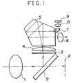
- Fig. 1 is a figure showing the construction of the optical system of a camera which is a first preferred embodiment of the present invention
- Fig. 2 is a functional block diagram showing the construction of the control system of this camera according to the first preferred embodiment.
- a light bundle from the object to be photographed passes through a photographic lens 1, is reflected off a quick return mirror 2, and arrives at a focusing screen 3, on which it is focused to produce an image of the object to be photographed.
- a first portion of a light bundle from this image of the object to be photographed focused upon the focusing screen 3 passes through a condenser lens 4, a pentaprism 5, and a eyepiece lens 6, and arrives at the eyeball of the photographer, and another portion thereof passes through the condenser lens 4 and the pentaprism 5 and through a prism 7 for photometry and through a lens 8 for photometry which focuses an image of the object to be photographed upon a photometric element 9.
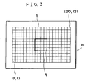
- the photometric element 9, as shown in Fig. 3, is constructed with photometric regions which divide up the photographic field H into 240 sections, 20 horizontally by 12 vertically, and each of these photometric regions detects the brightness of a corresponding portion of the image of the object to be photographed focused thereon. Further, each of these photometric regions is distinguished by an address affixed thereto, from the lower left photometric region which has the address (1,1) to the upper right photometric region which has the address (20,12).
- the control system for this camera is provided with a photometric section 10, an exposure calculation section 11, a target object follow up section 12, a control circuit 13, an exposure control section 14, and a movement prediction section 15.
- the photometric section 10 detects the brightness of the light incident upon each of the regions of the photometric element 9, and outputs corresponding brightness information.
- the exposure calculation section 11 inputs this brightness information from the photometric section 10 and calculates appropriate exposure value information based upon this brightness information.
- the target object follow up section 12 inputs the brightness information from the photometric section 10, and performs follow up of the target object to be photographed as it moves in the photographic field based upon this brightness information.
- the control circuit 13 comprises a CPU and its associated circuitry, and inputs the appropriate exposure value information from the exposure calculation section 11 and performs calculation of aperture opening amount and shutter speed and the like based thereupon, as well as controlling the exposure control section 14 so as to perform exposure control based upon these calculated values of aperture opening amount and shutter speed.
- the movement prediction section 15 predicts the movement within the photographic field of the object to be photographed while exposure action is taking place, based upon the value of shutter speed which it inputs from the control circuit 13 when the photographer initiates shutter release and upon follow up information for the target object to be photographed which it inputs from the target object follow up section 12, and outputs this movement information after exposure action has been completed to the target object follow up section 12.
- a first stroke switch 16 is arranged so as to be closed when a shutter release button not shown in the figures is depressed as far as a first stroke position thereof, and a second stroke switch 17 is arranged so as to be closed when said shutter release button is depressed fully to a second stroke position thereof.
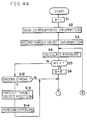
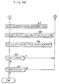
- Fig. 4A and Fig. 4B are flow charts showing the operation of a control program for the microcomputer incorporated in the control circuit 13 of this first preferred embodiment. The follow up operation for a target object to be photographed will now be explained with reference to these flow charts.
- the control circuit 13 starts to execute this control program when the first stroke switch 16 is closed.
- the value of a register n is initialized to unity. This register n is used as a flag for showing whether or not the program loop including the steps S4 through S14 is being executed for the first time: if the register n is set to unity this shows that the loop is being executed for the first time, while if the register n is set to zero this shows that the loop is being executed for the second or a subsequent time.
- the photometric section 10 performs photometry of the photographic field H, and brightness information is read in for each of the photometric regions into which said photographic field H is subdivided.
- step S3 information regarding the target object to be photographed is extracted from the brightness information thus obtained for the various photometric regions, and this information is recorded in the target object follow up section 12.
- the object to be photographed which lies within a square photometric region R made up, as shown in Fig. 3, of 16 photometric region elements (four horizontally by four vertically) which is located in the central portion of the photographic field H is taken as the object to be photographed which is to be followed up, and the brightness information for the 16 photometric regions included in this square photometric region R is recorded.
- this photometric region R composed of 16 photometric region elements (four horizontally by four vertically) which is set for follow up of a moving target object to be photographed will be termed the target object follow up region.
- step S4 calculation of an appropriate exposure value BVa is performed by the exposure calculation section 11.
- step S5 a decision is made as to whether or not the value of the flag register n is unity, i.e. as to whether or not this program loop is being executed for the first time.
- step S6 the value of the flag register n is reset to zero, and the flow of control proceeds to the step S7, in which photometry of the photographic field H is performed by the photometric section 10, and brightness information is read in for each of the photometric regions.
- the object to be photographed follow up calculation is performed by the target object follow up section 12.
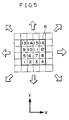
- the items of information representing the brightnesses of these 16 regions may be respectively termed B1 through B16.
- setting a total of eight new target object follow up regions by sliding the current target object follow up region R forwards and backwards by one region respectively in the X direction, in the Y direction, and in the two diagonal directions, a total of 9 possible new target object follow up regions including the present target object follow up region R are considered.
- the information recorded in the step S3 is used as the brightness information Bx when this program loop is being executed for the first time, while when this program loop is being executed for the second and subsequent times the information recorded during the previous execution of this program loop is used.
- the newest brightness information obtained just previously in the preceding step S7 is used as the brightness information Bx'.
- the comparison values D are obtained for the 9 possible new target object follow up regions, and that one thereof for which the comparison value D thus obtained from the equation (2) is the smallest is taken as the follow up region to which the object to be photographed has moved, i.e. as the new target object follow up region R.
- Fig. 6A there is shown the position of the target object within the target object follow up region R calculated by the target object follow up calculation performed in the step S8 as described above.
- the brightness information and the positional information for the 16 photometric regions included in the target object follow up region R as shown by the solid line are recorded as the follow up target object information.
- the comparison value D calculated according to the equation (2) between the target object follow up region R the time before as shown in Fig. 6B by the dotted line and the region R' shifted in the upwards and rightwards diagonal direction therefrom as shown by the solid line will be the smallest one of these nine comparison values which are calculated. Therefore, because the mutual relationship between these two regions is found to be the strongest, accordingly the object to be photographed follow up region R is shifted from its position as shown by the dotted line to the new position as shown by the solid line, i.e. is displaced in the upwards and rightwards direction, and thereby follow up of the moving target object to be photographed is performed. And the target object follow up section 12 records the positional information and the brightness information for each of the sixteen photometric regions within this new target object follow up region R, and makes them available for the next time this program loop is executed.
- the velocity of movement of the target object to be photographed is calculated. This calculated velocity of movement will be used in the prediction of the position of the target object to be photographed after the conclusion of the exposure procedure.
- the velocity of movement is calculated based upon the newest position of the target object to be photographed as obtained in the step S8 during this current execution of the program loop and upon the position of the target object to be photographed as obtained in the step S8 during the previous execution of the program loop. Now, supposing that as shown in Fig.
- the addresses of the leftmost and lowermost photometric regions in the previous follow up region R and in the new follow up region R' for the target object to be photographed are respectively (x1,y1) and (x2,y2), and supposing that the time period taken from sampling the data shown in Fig. 6A to sampling the data shown in Fig.
- step S10 of Fig. 4B a decision is made from the output of the first stroke switch 16 as to whether or not the shutter release button is being pressed through its first stroke, and if the shutter release button is being pressed through its first stroke then the flow of control returns to the previously described step S4, while if the shutter release button is not being pressed through its first stroke then the flow of control passes to the step S11.
- step S11 a decision is made as to whether or not a first stroke timer, which measures time for a set time period from when the shutter release button is pressed through its first stroke, has run out. If the first stroke timer has run out then processing ends, while if the first stroke timer has not run out then the flow of control returns to the previously described step S4.
- step S5 a decision is made as to whether or not the value of the register n is unity, i.e. as to whether or not the program loop is being executed for the first time. Since the execution of the program loop for the first time has already been completed, the value of the register n is set to zero, and the flow of control passes next to the step S12.
- step S12 a decision is made according to the output of the second stroke switch 17 as to whether or not the shutter release button is being pressed through its second stroke. If the shutter release button is being pressed through its second stroke, then the flow of control proceeds to the step S13, while if not then the flow of control is transferred to the step S7 and the above described processing is repeated.
- the shutter is thus being second stroke released, prediction of the position of the target object to be photographed is performed in the step S13 by the movement prediction section 15.
- Figs. 7A through 7C The method for prediction of the movement of the position of the target object to be photographed will now be explained with reference to Figs. 7A through 7C.
- the target object S to be photographed within the target object follow up region R has been followed up, and that this target object S, as shown by the arrow sign, is moving in the rightwards direction in the figure.
- the target object S to be photographed moves as far as the position shown in Fig.
- the thus calculated predicted position (Xn+1, Yn+1) of the target object S to be photographed is used as recorded data for refreshment of the positional information for the target object S after the conclusion of the exposure process, and the system continues to follow up the moving target object based upon this positional information.
- the target object follow up region R is shifted along to the predicted position, whereby it is possible to acquire the target object S, so that it becomes possible to continue accurate follow up of the target object S.
- step S14 of Fig. 4 based upon the appropriate exposure value obtained in the step S4, an limiting aperture mechanism and a shutter mechanism are operated by the exposure control section 14 so as to perform the exposure process, and thereafter the flow of control returns to the step S7 and the above described process is repeated.
- Fig. 9 is a sectional view of the camera according to the second preferred embodiment of the present invention.
- a ray bundle from the target object to be photographed passes through a photographic lens 53 and an limiting aperture 54 within a photographic lens unit 52 and is reflected off a main mirror 55 (in its state shown by the dashed lines) included in the camera body 51, and then passes through a screen 56, a pentaprism 57, and an eyepiece lens 58 to reach the eyeball of the photographer. Further, a portion of the ray bundle passes from the pentaprism 57 through a prism 59 and a focusing lens 60 and arrives at a photometric element 61. Yet further, another portion of the ray bundle passes from the pentaprism 57 through a focusing lens 68 and arrives at a photometric element 69.
- Various data relating to the photographic lens 53 are recorded within a ROM 62 within the lens, and photographic distance information X is obtained based upon these data and upon the position of the photographic lens 53, and is transmitted to the camera body 51 along with aperture opening value of the limiting aperture 54 and the like. And an attitude detection device 63 detects the attitude of the camera body 51.
- a photometric element 67 is an element for measuring the brightness level of flash illumination, which is used when performing flash photography with a flash device not shown in the drawings. Light emitted from the flash device and reflected from the object to be photographed passes through the photographic lens 53 and through the limiting aperture 54 and is reflected from the surface of the film 65, passes through a focusing lens 66, and arrives at the photometric element 67 for flash photometry.
- Fig. 10 shows a first possible example for the disposition of the photometric elements 61, 69a, and 69b.
- Fig. 10 is a view as seen looking at the pentaprism 57 from the vicinity of the eyepiece lens 58, and, in order conveniently to explain the arrangement of the elements, the orientations of the elements and the like are drawn somewhat differently from those shown in Fig. 9.
- the photometric element 61 which performs photometry using a ray bundle at the upper side of the eyepiece lens 58
- the photometric element 69 is split into two portions 69a and 69b which perform photometry using ray bundles on both the left and the right sides of the eyepiece lens 58.
- the photometry is performed by splitting up the photographic field into a central portion and four regions surrounding it, so as to give a total of five regions, and for the central portion the pair of left and right elements are superimposed upon the photometric region, and the two photometric values produced thereby are compounded together and taken as the photometric value for the central portion.
- Fig. 11 shows a second possible example for the disposition of the photometric elements 61 and 69.
- Fig. 11 is a view as seen looking at the pentaprism 57 from the vicinity of the eyepiece lens 58, and, in order conveniently to explain the arrangement of the elements, the orientations of the elements and the like are drawn somewhat differently from those shown in Fig. 9.
- the figure shows a view as seen from the side of the eyepiece lens 58 looking at the pentaprism 57, and therefore, since the explanation of the arrangement is the primary objective, the orientation of the elements and the like is drawn considerably differently from Fig. 51.
- the photometric element 69 performs photometry using a ray bundle at the left side of the eyepiece lens 58. In this case the photometry is performed in a unitary fashion, and the photographic field is not split up into regions.
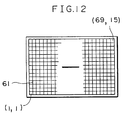
- the photometric element 61 is a two dimensional color CCD of the same type as is used in a video camera or the like, and as shown in Fig. 12 performs photometry by, via the focusing lens 60, splitting up the image of the photographic field on the screen 56 into a total of 1035 photometric regions, 69 horizontally by 15 vertically, and can then detect the brightness of each of these individual photometric regions. An address is appended to each of these regions, and, with the camera body 51 being held in the horizontal position, the lower leftmost region is addressed as (1,1) and the upper rightmost region is addressed as (69,15). Further, filters colored in the three primary colors R, G, and B are arranged over the photometric regions of the photometric element 61 in a repeated fashion as shown in Fig.
- the construction is enabled to detect the brightness of each of the photometric regions along with separating the image into the three primary colors.
- the filters it would also be acceptable for the filters to be colored, not in the primary colors R, G, and B, but in the complementary colors.
- Fig. 14 is a figure showing the internal construction of the photometric element 61.
- photoelectric conversion elements (photodiodes) 61a are provided, arranged in 69 columns as seen in the horizontal direction and in 15 rows as seen in the vertical direction.
- a row of shift registers 61b (hereinafter termed the H registers) is provided under each horizontally extending of these photoelectric conversion elements 61a, and the electric charges generated by the photoelectric conversion performed by the photoelectric conversion elements 61a are accumulated for a predetermined time period by a charge accumulation section not shown in the figure, and then are transferred to the H registers 61b all together.
- V registers 61c At the left ends in the figure of the H registers there are provided V registers 61c, and the electric charges transferred from the H registers 61b are transmitted in the upwards direction in the figure and are converted into voltages by a floating diffusion amplifier not shown in the drawings, and thereafter are output to an amplifier, also not shown.
- Optically black portions 61d are provided for interrupting light from the faces of photoelectric conversion elements 61a, and they output dark signals.
- H registers 61b are also provided under these optically black portions 61d, and, after the electric charges of the dark signals generated by the optically black portions 61d have been accumulated for a predetermined time period by a charge accumulation section not shown in the figure, they are then transferred to the H registers 61b all together, and further are transferred in the upward direction in the direction by the H registers 61b and the V registers 61c, are converted into voltages, and are output to an amplifier, also not shown.
- dark signal value compensation for the photoelectric conversion elements 61a can be performed.
- Separate optically black portions 61e and 61f are also provided for interrupting light from the faces of photoelectric conversion elements 61a, just like the optically black portions 61d, and mutually different predetermined amounts of electric charge are input from the charge accumulation section 61g to the 61e row of photoelectric conversion elements 61a and to the 61f row of photoelectric conversion elements 61a respectively. Since outputs are obtained from the rows including these optically black portions 61e and 61f which correspond to the temperatures of their photoelectric conversion elements 61a, thereby, based upon these signals, temperature variations of the photometric outputs of the photometric elements 61 output from the amplifier can be compensated for.
- the photometric element 69 is a photodiode which has been used in the prior art for photometry in a camera, and its output is an electric current which corresponds to the strength of the light which is measured.
- This photometric element 69 is used instead of the photometric element 61 for measuring the brightness of the object to be photographed, when light of high brightness falls upon some of the photoelectric conversion elements 61a of the photometric element 61 and they overflow, and this affects the outputs of the others of the photoelectric conversion elements 61a.
- a photometric element 69 of a type which performs photometry on 5 regions into which the photographic field is divided is used.
- the number of regions into which the photometric element 69 splits the photographic field is not, in this second preferred embodiment, to be considered as being particularly limited.
- Fig. 15 is a functional block diagram showing the general construction of the second preferred embodiment of the present invention.
- the outputs LV(m,n) of the photometric element 61 on the one hand are conversion calculated into brightness values BV(m,n) by a brightness information calculation conversion device 71 and are inputted to a microcomputer 73, and further on the other hand are converted into a color temperature CT by a color temperature information calculation conversion device 72 and are input to the microcomputer 73.
- the photometric element 61 is a sensor of a charge accumulation type, which accumulates the electric charges output from the photoelectric conversion elements 61a for a predetermined time period and reads out the accumulated charges in order. Since with the charge accumulation type of photoelectric conversion element a comparatively high bias voltage is applied, the problems have arisen that the dark signal is increased and the noise level is elevated, and in low illumination the photometric capability is bad. In particular, the dark signal is increased in high temperature conditions.
- the photometric element 69 is a photoelectric conversion element which outputs a current corresponding to the brightness of the light which is incident upon it, and a comparatively low bias voltage is applied to such a photoelectric conversion element. For this reason the dark signal is low, and no problem of the type described above with regard to the photometric element 61 occurs. Furthermore, even in high temperature conditions the dark signal does not become particularly high, and no such problem occurs.
- the attitude detection device 63 detects the attitude of the camera body 51 and inputs its result to the microcomputer 73.
- the attitude of the camera which is sensed can be either of three attitudes: a horizontal or landscape position, a vertical or portrait position in which the pentaprism 57 lies on the right side, and a vertical or portrait position in which the pentaprism 57 lies on the left side.
- An image sensor 77 and a focus detection circuit 78 detect the focus adjustment condition of the photographic lens for a left region thereof, for a middle region thereof, and for a right region thereof, and transfer the result of detection to the microcomputer 73.
- Lens data such as photographic distance information X which is detected based upon the position of the photographic lens 53, information regarding the aperture value of the limiting aperture 54, and the like are transferred from the photographic lens unit 52 to the microcomputer 73 within the camera body 51.
- the microcomputer 73 calculates the most appropriate exposure value BVans based upon the information which is input from the various devices described above, and controls a display control device 75 so as to display the result on a display device 76, and further, when the shutter release button of the camera is pressed through its second stroke, controls a exposure control device 74 so as to drive the limiting aperture 54 and the shutter 64 in such a manner as to expose the current film frame according to this calculated most appropriate exposure value BVans.
- Figs. 16 through 18 are for explanation of the operation of the color temperature information calculation conversion device 72.
- Fig. 18 is a figure showing the Planckian locus and isocolor-temperature lines.
- the color temperature is determined from the x-y values obtained from the previous equations by seeing on which isocolor-temperature line they fall.
- 345 items of color temperature information are obtained corresponding to a third of 1035, i.e. 345 regions, but the color temperature information calculation conversion device 72 determines the average value thereof, and takes it as the color temperature for the entire photographic field as a whole.
- Fig. 19 is a figure showing the gist of the follow up process for a moving target object.
- the photographer captures the object to be photographed which is to be the target for follow up in a follow up frame set in the center of the photographic field, and, when the shutter release button is pressed through its first stroke, the camera discerns the object to be photographed which lies in this follow up frame in the center of the photographic field as being the target object to be photographed, and records the photometric data within the follow up frame as information representative of the principal object to be photographed.
- the time point t1 which may for example be 20 ms later, photometry of the target object is performed, and all of the photometric data for the entire photographic field and the thus recorded photometric data for the object to be photographed which is the follow up target are compared.
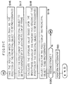
- Figs. 20A through 20C are flow charts for the operation of the microcomputer 73, showing a first variant of the target object follow up operation of this second preferred embodiment of the present invention.
- the first variant of the operation of target object follow up in this second preferred embodiment will now be explained with reference to these flow charts.
- step S51 the outputs BV(m,n) from the 27 photometric regions (31,7) to (39,9) which constitute the central portion of the photographic field on the photometric element 9 are read in.
- m ranges from 31 through 39
- n ranges from 7 through 9.
- step S52 a follow up frame on the display device 76 which surrounds the region corresponding to these 27 central photometric regions (31,7) to (39,9) on the photometric element 9 is displayed as flashing.
- step S53 a decision is made as to whether or the shutter release button of the camera is being depressed by the photographer as far as its first stroke position, and if the shutter release button is being first stroke depressed the flow of control proceeds to the step S54, while if the shutter release button is not being first stroke depressed the flow of control returns to the step S51 and the above described procedure is repeated.
- step S54 the display of the follow up frame in the central portion of the photographic field is turned off as a sign that the image of the object to be photographed at the central portion of the field has been discerned by the photographer as the follow up target object to be photographed.
- the count variables f and g which are for counting around the inner loops of this section of the program, are set to their initial values of zero, and the value Pmin which shows the correlation and the parameter Po are respectively set to predetermined values C1 and C2.
- the count variable f is incremented
- the count variable g is incremented.
- step S61 a decision is made as to whether or not the value of P is less than the current value of Pmin, and if P is smaller than Pmin the flow of control passes to the step S62, while if P is not smaller than Pmin then the flow of control skips past the step S62 to the step S63.
- step S62 Pmin is reset to the current value of P, and the current values of f and g are stored respectively in the memory f0 and g0.
- step S63 a decision is made as to whether or not the value of g is equal to 13, and if g is equal to 13 then the flow of control proceeds to the next step S64, while if g is not yet equal to 13 then the flow of control loops back to the step S59 again.
- step S64 a decision is made as to whether or not the value of f is equal to 61, and if f is equal to 61 then the flow of control proceeds to the next step S65, while if f is not yet equal to 61 then the flow of control loops back to the step S58 again.
- step S65 a decision is made as to whether or not Pmin is greater than the value P0, and if Pmin is greater than the predetermined P0 then follow up of the target object to be photographed is deemed to be impossible (the target has been lost) and the flow of control returns back to the step S51, and the system goes into waiting state until again the shutter release button of the camera is depressed as far as its first stroke position by the photographer, at which time the image of the object to be photographed which is currently at the central portion of the photographic field is discerned as the follow up target object to be photographed. At this time, the display of the follow up frame at the central portion of the photographic field is flashed, and the driving of the lens for focus adjustment is prevented.
- step S65 it is deemed that Pmin is not greater than the predetermined value P0, then the flow of control is transferred to the step S66 of the Fig. 20C flow chart, and the new position of the principal object to be photographed is taken as being the position of the 27 photometric regions which gives the value Pmin. That is to say, it is deemed that the principal object to be photographed which is the subject of follow up as recorded in the step S55 has moved within the photographic field, and to have moved to the position which determined from the values of f and g stored in the memory f0 and g0.
- step S67 the 27 photometric elements constituting the field which in the step S66 was decided to be the position of the principal object to be photographed are displayed by a flashing follow up frame surrounding them.
- step S68 an exposure value is calculated based upon the brightness values Bv of these 27 photometric elements constituting the field which in the step S66 was decided to be the position of the principal object to be photographed.
- step S69 the focus of the photographic lens 53 is adjusted for the position decided in the step S66 to be the position of the principal object to be photographed.
- step S70 a decision is made as to whether or not the shutter release button of the camera is being pressed through its second stroke by the photographer, and if the shutter release button is in fact being second stroke pressed for performing shutter release then the flow of control passes to the next step S71 and photography is performed and then this control program terminates, while if the shutter release button is not being second stroke pressed then the flow of control returns back to the step S56 of Fig. 20A and the above described process is repeated.
- Figs. 21A through 21C are flow charts for the operation of the microcomputer 73, showing a second variant of the target object follow up operation of the second preferred embodiment of the present invention.
- step S65 when in the step S65 the value of Pmin was found not to be less than or equal to the predetermined value P0, target follow up was considered to be impossible, and the flow of control returned to the step S51, and the system went into the waiting state until the time point when again the photographer pressed the shutter release button as far as its first stroke, at which time the image of the object at the center of the photographic field was discerned as the follow up target.
- step S115 the decision is made as to whether or not the value of Pmin is greater than the predetermined value P0, and when the value of Pmin is found not to be less than or equal to the predetermined value P0, then target follow up is considered to be impossible, and the flow of control is transferred to the step S122, in which the position of the object to be photographed which gave the value Pmin during the correlation calculation for the previous iteration of the program loop is shown by a flashing follow up box around it, and the driving of the lens for focus adjustment is prevented and the flow of control returns to the step S106.
- the brightness pattern of the object to be photographed which was discerned in the beginning in the center of the photographic field and the brightness patterns of each of the possible sets of 27 (9 ⁇ 3) photometric regions in the photographic field are compared and correlation calculation is performed again.
- the process of follow up of the target object to be photographed described above with reference to Figs. 20A through 20C when target follow up was considered to be impossible, the process was performed again by discerning the object to be photographed at the center of the photographic field as the target object to be followed up.
Landscapes
- Engineering & Computer Science (AREA)
- Multimedia (AREA)
- Signal Processing (AREA)
- Physics & Mathematics (AREA)
- Electromagnetism (AREA)
- General Physics & Mathematics (AREA)
- Radar, Positioning & Navigation (AREA)
- Remote Sensing (AREA)
- Exposure Control For Cameras (AREA)
Applications Claiming Priority (4)
| Application Number | Priority Date | Filing Date | Title |
|---|---|---|---|
| JP39367/93 | 1993-02-02 | ||
| JP03936793A JP3237273B2 (ja) | 1993-02-02 | 1993-02-02 | 被写体追尾機能を有するカメラ |
| JP5027066A JPH06242486A (ja) | 1993-02-17 | 1993-02-17 | カメラの主要被写体認識装置 |
| JP27066/93 | 1993-02-17 |
Publications (1)
| Publication Number | Publication Date |
|---|---|
| EP0609948A1 true EP0609948A1 (fr) | 1994-08-10 |
Family
ID=26364947
Family Applications (1)
| Application Number | Title | Priority Date | Filing Date |
|---|---|---|---|
| EP94200265A Ceased EP0609948A1 (fr) | 1993-02-02 | 1994-02-01 | Caméra ayant une fonction de poursuite de cible |
Country Status (2)
| Country | Link |
|---|---|
| US (1) | US5475466A (fr) |
| EP (1) | EP0609948A1 (fr) |
Families Citing this family (9)
| Publication number | Priority date | Publication date | Assignee | Title |
|---|---|---|---|---|
| US5739856A (en) * | 1993-10-07 | 1998-04-14 | Nikon Corporation | Photographic subject position predicting apparatus |
| US6441848B1 (en) | 2000-05-19 | 2002-08-27 | Damon L. Tull | Preventing blur caused by motion of the subject in a digital image |
| JP4366023B2 (ja) * | 2001-03-16 | 2009-11-18 | インターナショナル・ビジネス・マシーンズ・コーポレーション | ビデオ・イメージの部分イメージ領域抽出方法、部分イメージ領域抽出システム、部分イメージ領域抽出のためのプログラム、抽出されたビデオ・イメージの配信方法およびコンテンツ作成方法 |
| JP4574220B2 (ja) * | 2004-04-30 | 2010-11-04 | 富士フイルム株式会社 | 撮像装置及び撮像方法 |
| JP5321070B2 (ja) * | 2009-01-08 | 2013-10-23 | カシオ計算機株式会社 | 撮影装置、撮影方法及びプログラム |
| KR101597823B1 (ko) * | 2009-03-19 | 2016-02-26 | 삼성전자주식회사 | 움직임 보상 장치 |
| US8761594B1 (en) | 2013-02-28 | 2014-06-24 | Apple Inc. | Spatially dynamic illumination for camera systems |
| US11265480B2 (en) * | 2019-06-11 | 2022-03-01 | Qualcomm Incorporated | Systems and methods for controlling exposure settings based on motion characteristics associated with an image sensor |
| CN117245641A (zh) * | 2022-12-06 | 2023-12-19 | 北京小米机器人技术有限公司 | 目标跟随方法、装置及存储介质 |
Citations (2)
| Publication number | Priority date | Publication date | Assignee | Title |
|---|---|---|---|---|
| US5031049A (en) * | 1984-05-25 | 1991-07-09 | Canon Kabushiki Kaisha | Automatic object image follow-up device |
| GB2246261A (en) * | 1990-07-16 | 1992-01-22 | Roke Manor Research | Tracking arrangements and systems |
Family Cites Families (6)
| Publication number | Priority date | Publication date | Assignee | Title |
|---|---|---|---|---|
| JPS6033350B2 (ja) * | 1979-12-17 | 1985-08-02 | 三菱電機株式会社 | 相関追尾装置 |
| JPH01136460A (ja) * | 1987-11-20 | 1989-05-29 | Sanyo Electric Co Ltd | 読取り装置 |
| US5196929A (en) * | 1989-07-05 | 1993-03-23 | Olympus Optical Co., Ltd. | Display system of camera having tracking apparatus |
| KR950003569B1 (ko) * | 1990-04-19 | 1995-04-14 | 미쯔비시덴끼 가부시끼가이샤 | 촬상장치 및 이를 이용한 자동 초점맞춤 장치 |
| US5255044A (en) * | 1990-06-05 | 1993-10-19 | Nikon Corporation | Automatic exposure control apparatus with improved exposure value calculation for photographing a moving object |
| JP3103897B2 (ja) * | 1991-03-19 | 2000-10-30 | ソニー株式会社 | 手振れ補正装置および手振れ補正方法 |
-
1994
- 1994-01-27 US US08/187,310 patent/US5475466A/en not_active Expired - Fee Related
- 1994-02-01 EP EP94200265A patent/EP0609948A1/fr not_active Ceased
Patent Citations (2)
| Publication number | Priority date | Publication date | Assignee | Title |
|---|---|---|---|---|
| US5031049A (en) * | 1984-05-25 | 1991-07-09 | Canon Kabushiki Kaisha | Automatic object image follow-up device |
| GB2246261A (en) * | 1990-07-16 | 1992-01-22 | Roke Manor Research | Tracking arrangements and systems |
Also Published As
| Publication number | Publication date |
|---|---|
| US5475466A (en) | 1995-12-12 |
Similar Documents
| Publication | Publication Date | Title |
|---|---|---|
| US4716434A (en) | Focus condition detecting device | |
| US5758210A (en) | Focus detecting photoelectric converting apparatus for a camera | |
| US4851657A (en) | Focus condition detecting device using weighted center or contrast evaluation | |
| US5475466A (en) | Camera having target follow up function | |
| US4905032A (en) | Automatic focus detecting device | |
| JPS59126517A (ja) | カメラのピント検出装置 | |
| JPH10160410A (ja) | 測距装置 | |
| JPH0439635A (ja) | 測光装置 | |
| US5541706A (en) | Exposure calculation device for a camera | |
| US5144357A (en) | Automatic focus detecting means | |
| US5138358A (en) | Autofocusing apparatus utilizing intermittent light projection | |
| US5192998A (en) | In-focus detecting device | |
| US5721977A (en) | Distance measuring apparatus of camera improved in measuring process | |
| US5534968A (en) | Camera having variable photometry conditions | |
| JPH09127408A (ja) | イメージセンサおよびこれを用いた測距装置 | |
| US5835143A (en) | Automatic focusing system for a still video camera | |
| US5434640A (en) | Exposure calculation device for camera | |
| US5402201A (en) | Automatic flash control device of camera | |
| JPH04261508A (ja) | ピント検出用光電変換素子 | |
| JPH09121312A (ja) | イメージセンシングシステム | |
| JPH0727608A (ja) | カメラの測光装置 | |
| EP0436511B1 (fr) | Dispositif de détection de mise au point | |
| JPH03174127A (ja) | カメラの露出制御装置 | |
| JP4140069B2 (ja) | 焦点検出装置 | |
| JPH01289905A (ja) | カメラおよびカメラボディ |
Legal Events
| Date | Code | Title | Description |
|---|---|---|---|
| PUAI | Public reference made under article 153(3) epc to a published international application that has entered the european phase |
Free format text: ORIGINAL CODE: 0009012 |
|
| AK | Designated contracting states |
Kind code of ref document: A1 Designated state(s): DE FR |
|
| 17P | Request for examination filed |
Effective date: 19941025 |
|
| 17Q | First examination report despatched |
Effective date: 19970129 |
|
| GRAG | Despatch of communication of intention to grant |
Free format text: ORIGINAL CODE: EPIDOS AGRA |
|
| STAA | Information on the status of an ep patent application or granted ep patent |
Free format text: STATUS: THE APPLICATION HAS BEEN REFUSED |
|
| 18R | Application refused |
Effective date: 19980830 |