EP0609981A2 - Appareil de gonflage - Google Patents
Appareil de gonflage Download PDFInfo
- Publication number
- EP0609981A2 EP0609981A2 EP94300154A EP94300154A EP0609981A2 EP 0609981 A2 EP0609981 A2 EP 0609981A2 EP 94300154 A EP94300154 A EP 94300154A EP 94300154 A EP94300154 A EP 94300154A EP 0609981 A2 EP0609981 A2 EP 0609981A2
- Authority
- EP
- European Patent Office
- Prior art keywords
- gas generating
- generating material
- stage
- surface area
- igniting
- Prior art date
- Legal status (The legal status is an assumption and is not a legal conclusion. Google has not performed a legal analysis and makes no representation as to the accuracy of the status listed.)
- Granted
Links
- 239000000463 material Substances 0.000 claims abstract description 97
- 238000002485 combustion reaction Methods 0.000 claims description 82
- 239000007789 gas Substances 0.000 description 91
- 239000002893 slag Substances 0.000 description 8
- 238000011045 prefiltration Methods 0.000 description 6
- 238000003466 welding Methods 0.000 description 3
- OKTJSMMVPCPJKN-UHFFFAOYSA-N Carbon Chemical compound [C] OKTJSMMVPCPJKN-UHFFFAOYSA-N 0.000 description 2
- 230000000712 assembly Effects 0.000 description 2
- 238000000429 assembly Methods 0.000 description 2
- 229910002804 graphite Inorganic materials 0.000 description 2
- 239000010439 graphite Substances 0.000 description 2
- 229910052751 metal Inorganic materials 0.000 description 2
- 239000002184 metal Substances 0.000 description 2
- 230000004048 modification Effects 0.000 description 2
- 238000012986 modification Methods 0.000 description 2
- IJGRMHOSHXDMSA-UHFFFAOYSA-N Atomic nitrogen Chemical compound N#N IJGRMHOSHXDMSA-UHFFFAOYSA-N 0.000 description 1
- 229910052782 aluminium Inorganic materials 0.000 description 1
- XAGFODPZIPBFFR-UHFFFAOYSA-N aluminium Chemical compound [Al] XAGFODPZIPBFFR-UHFFFAOYSA-N 0.000 description 1
- 229910001873 dinitrogen Inorganic materials 0.000 description 1
- 229910001220 stainless steel Inorganic materials 0.000 description 1
- 239000010935 stainless steel Substances 0.000 description 1
- 230000002889 sympathetic effect Effects 0.000 description 1
Images
Classifications
-
- B—PERFORMING OPERATIONS; TRANSPORTING
- B60—VEHICLES IN GENERAL
- B60R—VEHICLES, VEHICLE FITTINGS, OR VEHICLE PARTS, NOT OTHERWISE PROVIDED FOR
- B60R21/00—Arrangements or fittings on vehicles for protecting or preventing injuries to occupants or pedestrians in case of accidents or other traffic risks
- B60R21/02—Occupant safety arrangements or fittings, e.g. crash pads
- B60R21/16—Inflatable occupant restraints or confinements designed to inflate upon impact or impending impact, e.g. air bags
- B60R21/26—Inflatable occupant restraints or confinements designed to inflate upon impact or impending impact, e.g. air bags characterised by the inflation fluid source or means to control inflation fluid flow
- B60R21/264—Inflatable occupant restraints or confinements designed to inflate upon impact or impending impact, e.g. air bags characterised by the inflation fluid source or means to control inflation fluid flow using instantaneous generation of gas, e.g. pyrotechnic
- B60R21/2644—Inflatable occupant restraints or confinements designed to inflate upon impact or impending impact, e.g. air bags characterised by the inflation fluid source or means to control inflation fluid flow using instantaneous generation of gas, e.g. pyrotechnic using only solid reacting substances, e.g. pellets, powder
-
- B—PERFORMING OPERATIONS; TRANSPORTING
- B60—VEHICLES IN GENERAL
- B60R—VEHICLES, VEHICLE FITTINGS, OR VEHICLE PARTS, NOT OTHERWISE PROVIDED FOR
- B60R21/00—Arrangements or fittings on vehicles for protecting or preventing injuries to occupants or pedestrians in case of accidents or other traffic risks
- B60R21/02—Occupant safety arrangements or fittings, e.g. crash pads
- B60R21/16—Inflatable occupant restraints or confinements designed to inflate upon impact or impending impact, e.g. air bags
- B60R21/26—Inflatable occupant restraints or confinements designed to inflate upon impact or impending impact, e.g. air bags characterised by the inflation fluid source or means to control inflation fluid flow
- B60R2021/26029—Ignitors
-
- B—PERFORMING OPERATIONS; TRANSPORTING
- B60—VEHICLES IN GENERAL
- B60R—VEHICLES, VEHICLE FITTINGS, OR VEHICLE PARTS, NOT OTHERWISE PROVIDED FOR
- B60R21/00—Arrangements or fittings on vehicles for protecting or preventing injuries to occupants or pedestrians in case of accidents or other traffic risks
- B60R21/02—Occupant safety arrangements or fittings, e.g. crash pads
- B60R21/16—Inflatable occupant restraints or confinements designed to inflate upon impact or impending impact, e.g. air bags
- B60R21/26—Inflatable occupant restraints or confinements designed to inflate upon impact or impending impact, e.g. air bags characterised by the inflation fluid source or means to control inflation fluid flow
- B60R21/263—Inflatable occupant restraints or confinements designed to inflate upon impact or impending impact, e.g. air bags characterised by the inflation fluid source or means to control inflation fluid flow using a variable source, e.g. plural stage or controlled output
- B60R2021/2633—Inflatable occupant restraints or confinements designed to inflate upon impact or impending impact, e.g. air bags characterised by the inflation fluid source or means to control inflation fluid flow using a variable source, e.g. plural stage or controlled output with a plurality of inflation levels
Definitions
- the present invention relates to an apparatus for inflating an inflatable vehicle occupant restraint, such as an air bag.
- U.S. Patent No. 5,100,174 An apparatus for inflating an air bag is disclosed in U.S. Patent No. 5,100,174.
- the apparatus disclosed in the '174 patent includes an inflator which generates gas for inflating the air bag.
- the inflator and the air bag are contained in a module which is mounted on a vehicle steering wheel.
- the inflator in the apparatus disclosed in the '174 patent contains a body of gas generating material which, when ignited, produces the gas for inflating the air bag.
- the inflator also contains an igniter which is actuated upon the occurrence of vehicle deceleration indicative of a collision.
- the igniter includes an ignition charge and an output charge. When the vehicle experiences deceleration indicative of a collision, the ignition charge is ignited electrically. The ignition charge then produces combustion products which ignite the output charge. The output charge, in turn, produces combustion products which emerge from the igniter to ignite the body of gas generating material in the inflator.
- a large volume of gas is rapidly generated as a product of combustion of the gas generating material.
- the gas flows through a plurality of filters in the inflator and outward from the inflator to the air bag for inflation of the air bag.
- an apparatus for use in inflating an inflatable vehicle occupant restraint comprises gas generating means and igniting means.
- the gas generating means generates gas to inflate the inflatable vehicle occupant restraint.
- the gas generating means includes an ignitable body of gas generating material which, when ignited, generates combustion products including the gas which inflates the vehicle occupant restraint.
- the igniting means ignites the body of gas generating material.
- the igniting means is actuatable in a first stage and, alternatively, in a second stage.
- the igniting means when actuated in the first stage, ignites the body of gas generating material at a first surface area of the body of gas generating material.
- the igniting means when actuated in the second stage, ignites the body of gas generating material at a second surface area which is greater than the first surface area.
- An apparatus constructed in accordance with the present invention enables an inflatable vehicle occupant restraint, such as an air bag, to be inflated at two different rates of inflation.
- the igniting means When the igniting means is actuated in the first stage, the body of gas generating material is ignited at the first surface area. The body of gas generating material then burns at a first rate of combustion, and generates gas at a first rate of gas generation. The air bag is thus inflated at a corresponding first rate of inflation.
- the igniting means is actuated in the second stage, the body of gas generating material is ignited at the second, greater surface area. The body of gas generating material then burns at a second, faster rate of combustion. The gas is then generated at a second, faster rate of gas generation, and the air bag is inflated at a corresponding second, faster rate of inflation.
- the igniting means includes an igniter containing output charge material.
- the output charge material when ignited, produces combustion products which emerge from the igniter to ignite the body of gas generating material.
- the output charge material includes a first output charge and a second output charge.
- the first output charge is ignited in response to a first electrical signal.
- the second output charge is subsequently ignited by the products of combustion emitted from the first output charge.
- the first and second output charges are thus ignited sequentially.
- the air bag is to be inflated at the second, relatively faster rate of inflation, the first and second output charges are ignited simultaneously in response to a second electrical signal.
- the resulting products of combustion emerge from the igniter more rapidly and forcefully than when the first and second output charges are ignited sequentially.
- the more rapidly emerging combustion products move against the body of gas generating material forcefully enough to cause a substantial increase in the surface area of the body by breaking the body.
- the body of gas generating material is ignited at a substantially greater surface area.
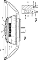
- a preferred embodiment of the present invention is a vehicle occupant restraint apparatus 10.
- the apparatus 10 includes an air bag 12, an inflator 14 and a cover 16.
- the air bag 12, the inflator 14 and the cover 16 are components of a module 18 which is mounted on a vehicle steering wheel 20.
- the inflator 14 Upon the occurrence of sudden vehicle deceleration, such as occurs in a collision, the inflator 14 is energized and produces a large volume of gas. The gas produced by the inflator 14 inflates the air bag 12. As the air bag 12 begins to inflate, it ruptures weakened portions 22 of the cover 16, one of which is shown in Figure 1. As the air bag 12 continues to inflate, it moves past the ruptured cover 16 and into the space between the driver of the vehicle and the steering wheel 20 to restrain movement of the driver, as is known.
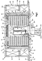
- the inflator 14 includes a housing 40.
- the housing 40 is made of three pieces, namely a diffuser cup 42, a combustion cup 44, and a combustion chamber cover 46.
- the diffuser cup 42, the combustion cup 44 and the combustion chamber cover 46 are made of metal, such as UNS S30100 stainless steel.
- the diffuser cup 42 is generally cup shaped, and has a cylindrical side wall 50 centered on the central axis 52 of the inflator 14.
- the side wall 50 of the diffuser cup 42 extends axially between a flat upper end wall 54 and a flat lower flange 55.
- the upper end wall 54 and the lower flange 55 are generally parallel to each other and perpendicular to the central axis 52.
- An annular inner surface 56 on the upper end wall 54 defines a central opening 57 in the upper end wall 54.
- An array of gas outlet openings 58 extends circumferentially around an upper portion of the cylindrical side wall 50.
- the combustion cup 44 also is generally cup shaped, and is located coaxially within the diffuser cup 42.
- the combustion cup 44 thus has a cylindrical side wall 60 centered on the axis 52.
- the cylindrical side wall 60 extends axially between a flat upper end wall 64 and a flat lower flange 66.
- the upper end wall 64 and the lower flange 66 are generally parallel to each other and perpendicular to the axis 52.
- An array of gas flow openings 68 extends circumferentially around a lower portion of the cylindrical side wall 60 of the combustion cup 44.
- the combustion cup 44 is welded to the diffuser cup 42, preferably by laser welding. Specifically, the upper end wall 64 of the combustion cup 44 is welded with a continuous weld to the upper end wall 54 of the diffuser cup 42 at a weld location 70 extending circumferentially about the annular inner surface 56 on the upper end wall 54.
- the lower flange 66 on the combustion cup 44 is welded to the lower flange 55 on the diffuser cup 42 at a weld location 72 extending circumferentially about the lower flanges 55 and 66.
- the combustion chamber cover 46 is a generally flat metal piece with a circular central portion 74 and an annular outer flange 76.
- the central portion 74 has an annular inner surface 77 defining a circular opening 78 which is centered on the axis 52.
- the flange 76 is parallel to, but axially offset from, the central portion 74.
- the flange 76 on the combustion chamber cover 46 is welded to the flange 66 on the combustion cup 44 at a circumferentially extending weld location 79, again preferably by laser welding.
- a canister 80 is contained within the combustion cup 44.
- the canister 80 has a generally cylindrical body 82 and a generally circular cover 84.
- the cover 84 supports a packet 86 of auto-ignition material 88.
- the packet 86 of auto-ignition material 88 is preferably designed and constructed in accordance with the invention set forth in U.S. Patent No. 5,100,174.
- the canister 80 is preferably made of relatively thin aluminum.
- the canister body 82 has a cylindrical inner side wall 90 and a cylindrical outer side wall 92.
- the outer side wall 92 of the canister body 82 is spaced radially from the inner side wall 90, and adjoins the cylindrical side wall 60 of the combustion cup 44.
- the outer side wall 92 of the canister body 82 has a relatively thin portion 94 extending over the gas flow openings 68 in the side wall 60 of the combustion cup 44.
- the canister body 82 further has a lower end wall 100 and an upper end wall 102.
- the lower end wall 100 is a flat, ring shaped portion of the canister body 82 which connects the cylindrical outer side wall 92 with the cylindrical inner side wall 90.
- a compartment 104 is thus defined within the canister 80.
- the compartment 104 extends radially between the inner and outer side walls 90 and 92, and extends axially between the lower end wall 100 and the cover 84.
- the radially outer edge portion of the cover 84 is crimped to an adjacent edge portion of the body 82 to close the canister 80 and to seal the compartment 104 hermetically.
- the upper end wall 102 of the canister body 82 is a cap shaped portion of the canister body 82 which closes the upper end of the cylindrical inner side wall 90.
- the lower end wall 100, the cylindrical inner side wall 90 and the upper end wall 102 thus define a cylindrical recess 108 extending axially upward into the center of the canister 80 from the lower end wall 100 to the upper end wall 102.
- a body 110 of gas generating material is contained in the canister 80.
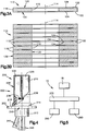
- the body 110 of gas generating material includes a plurality of individual elements 112 (Figs. 3A and 3B) of gas generating material.
- Each of the elements 112 of gas generating material is made of a known ignitable material which, when ignited, generates nitrogen gas.
- gas generating material could be used, especially suitable gas generating materials are disclosed in U.S. Patent No. 3,895,098.
- each of the elements 112 of gas generating material is a flat, ring shaped member having a central axis 114.
- Each of the elements 112 of gas generating material further has a cylindrical inner surface 116, a cylindrical outer surface 118, and a pair of annular opposite side surfaces 120.
- Each of the opposite side surfaces 120 has an annular abutment portion 122 and an annular recessed portion 124.
- the abutment portion 122 of each opposite side surface 120 extends radially inward from the cylindrical outer surface 118.
- the recessed portion 124 of each opposite side surface 120 extends radially outward from the cylindrical inner surface 116 to the associated abutment portion 122.
- the elements 112 of gas generating material are arranged in a stack. Adjoining pairs of the annular abutment surface portions 122 are contiguous with each other, and are thus coaxial with each other. Adjoining pairs of the cylindrical inner surfaces 116, and adjoining pairs of the cylindrical outer surfaces 118, likewise are coaxial with each other.
- the body 110 of gas generating material thus has a tubular shape with a cylindrical outer surface 130 and a cylindrical inner surface 132.
- the cylindrical outer surface 130 is defined by the individual cylindrical outer surfaces 118.
- the cylindrical inner surface 132 is defined by the individual cylindrical inner surfaces 116. However, the cylindrical inner surface 132 is interrupted axially by each of a plurality of annular gaps 134 located axially between adjoining pairs of the recessed annular surface portions 124.
- the tubular body 110 of gas generating material is contained in the hermetically sealed compartment 104 within the canister 80.
- the cylindrical inner surface 132 of the body 110 is spaced slightly from the cylindrical inner side wall 90 of the canister 80.
- the cylindrical outer surface 130 of the body 110 is spaced a greater distance from the cylindrical outer side wall 92 of the canister 80.
- a resilient elastomeric spacing member 140 located between the body 110 of gas generating material and the canister cover 84 holds the body 110 from shifting out of the position shown in Figure 2.
- a prefilter 150 also is contained in the compartment 104 within the canister 80.
- the prefilter 150 has a cylindrical shape, and is located radially between the cylindrical outer surface 130 of the body 110 of gas generating material and the cylindrical outer side wall 92 of the canister 80.
- the prefilter 150 can be constructed as known in the art.
- the inflator 14 further includes a slag screen 180 and a final filter 182, as shown schematically in Fig. 2.
- the slag screen 180 and the final filter 182 are both located in the annular space defined between the combustion cup 44 and the diffuser cup 42.
- the slag screen 180 is a ring shaped member which extends circumferentially around, and axially across, the array of gas flow openings 68 in the cylindrical side wall 60 of the combustion cup 44.
- the final filter 182 also is a ring shaped member.
- the final filter 182 similarly extends circumferentially around and axially across the array of gas outlet openings 58 in the cylindrical side wall 50 of the diffuser cup 42.
- the final filter 182 is radially narrower than the slag screen 180, and is thus spaced radially from the cylindrical side wall 60 of the combustion cup 44.
- An annular filter shield 184 separates the slag screen 180 from the final filter 182.
- a first annular graphite seal 186 seals the gap between the top of the final filter 182 and the flat upper end wall 54 of the diffuser cup 42.
- a second annular graphite seal 188 similarly seals the gap between the bottom of the final filter 182 and the filter shield 184.
- the slag screen 180 and the final filter 182 can be constructed as known in the art.
- the inflator 14 is constructed to direct gas from the hermetically sealed compartment 104 in the canister 80 to the gas outlet openings 58 in the housing 40.
- the body 110 of gas generating material When the body 110 of gas generating material is ignited in the compartment 104, it produces combustion products including a large volume of gas.
- the gas produced by the body 110 of gas generating material moves radially outward from the body 110 and through the prefilter 150 to the cylindrical outer side wall 92 of the canister 80.
- the gas moves radially outward against the thin portion 94 of the outer side wall 92 forcefully enough to rupture the thin portion 94 at the gas flow openings 68 in the combustion cup 44.
- the gas is then directed radially outward through the gas flow openings 68 and into the slag screen 180.
- the gas is further directed axially upward past the filter shield 184, and radially outward through the final filter 182 to the gas outlet openings 58 in the diffuser cup 42.
- the prefilter 150, the slag screen 180 and the final filter 182 remove other combustion products from the gas so that the gas is cooled and filtered before it flows from the gas outlet openings 58 to the air bag 12.
- the inflator 14 further includes an igniter assembly 200.
- the igniter assembly 200 extends axially through the lower opening 78 in the housing 40 and into the cylindrical recess 108 at the center of the canister 80.
- the igniter assembly 200 has a circular base plate 202 which is welded, preferably by laser welding, to the circular central portion 74 of the combustion chamber cover 46 at a circumferentially extending weld location 204.
- the igniter assembly 200 includes a pressure cartridge 206.
- the pressure cartridge 206 has a cylindrical housing 208 with an upper portion 210, a lower portion 212, and a flange portion 214 between the upper and lower portions 210 and 212.
- the lower portion 212 of the housing 208 is closely received through an opening 216 in the center of the base plate 202, and the flange portion 214 of the housing 208 is supported on a flat upper surface 218 of the base plate 202.
- the upper portion 210 of the housing 208 is formed as a thin, rupturable closure wall of the pressure cartridge 206.
- the pressure cartridge 206 contains ignitable material for igniting the body 110 of gas generating material in the canister 80.
- the ignitable material contained in the pressure cartridge 206 includes a first output charge 230 and a second output charge 232.
- Each of the first and second output charges 230 and 232 is formed as a body of ignitable material which, when ignited, produces combustion products for igniting the body 110 of gas generating material in the canister 80.
- Both the first and second output charges 230 and 232 are preferably formed of BKNO3.
- the ignitable material contained in the pressure cartridge 206 further includes first and second ignition charges 236 and 238.
- the first ignition charge 236 is located within the housing 208 in a position adjoining the lower end of the first output charge 230.
- the first ignition charge 236, when ignited, produces combustion products which ignite the first output charge 230.
- the second ignition charge 238 is located within the housing 208 in a position adjoining the lower end of the second output charge 232.
- the second ignition charge 238, when ignited, produces combustion products which ignite the second output charge 232.
- the igniter assembly 200 further includes electrical lead wires extending into the pressure cartridge 206.
- a pair of first lead wires 240 is associated with the first ignition charge 236 in a known manner to ignite the first ignition charge 236 upon the passage of electric current through the pressure cartridge 206 between the first lead wires 240.
- a pair of second lead wires 242 is similarly associated with the second ignition charge 238 to ignite the second ignition charge 238 upon the passage of electric current through the pressure cartridge 206 between the second lead wires 242.
- the igniter assembly 200 can be actuated in a first stage or in a second stage.
- electric current is directed through the pressure cartridge 206 between the first lead wires 240 but not between the second lead wires 242.
- the first ignition charge 236 is thus ignited electrically, and produces combustion products which ignite the first output charge 230.
- the second output 232 charge is then ignited by sympathetic ignition by the heat produced by the first output charge 230.
- the first and second output charges 230 and 232 are thus ignited sequentially. As the first and second output charges 230 and 232 burn following sequential ignition, they produce first stage combustion products including heat and a pressure wave.
- the first stage combustion products produced by the first and second output charges 230 and 232 rupture the closure wall 210, and move from the pressure cartridge 206 toward the cylindrical inner side wall 90 of the canister 80.
- the first stage combustion products also rupture the cylindrical inner side wall 90 and move into the compartment 104 within the canister 80 to ignite the body 110 of gas generating material in the compartment 104.
- the first stage combustion products move against each of the elements 112 of the gas generating material simultaneously.
- the first stage combustion products thus move against the entire cylindrical inner surface 132 of the body 110, and also move against the recessed surface portions 124 of the body 110 within the gaps 134.
- the first stage combustion products thus ignite the body 110 of gas generating material at a first ignitable surface area of the body 110 which is defined by the cylindrical inner surface 132 and the recessed surface portions 124.
- the first stage combustion products may form cracks in the body 110 of gas generating material, in which case the first ignitable surface area of the body 110 would further include the surfaces located within the cracks.
- the body 110 of gas generating material When the body 110 of gas generating material has been ignited at the first ignitable surface area by the first stage combustion products, it proceeds to burn at a first rate of combustion. As a result, the body 110 of gas generating material generates gas for inflating the air bag 12 at a first rate of gas generation.
- first and second ignition charges 236 and 238 are thus ignited simultaneously.
- the first and second ignition charges 236 and 238 then produce combustion products which ignite the first and second output charges 230 and 232 simultaneously.
- the first and second output charges 230 and 232 burn following simultaneous ignition, they produce second stage combustion products.
- the second stage combustion products include heat and a pressure wave.
- the second stage combustion products are produced more rapidly because the first and second output charges 230 and 232 are ignited in the second stage simultaneously rather than sequentially.
- the second stage combustion products therefore include a greater amount of heat and a more forceful pressure wave.
- the second stage combustion products move from the pressure cartridge 206 into the compartment 104 in the canister 80 more rapidly and forcefully than the first stage combustion products.
- the second stage combustion products also move against each of the elements 112 of gas generating material simultaneously.
- the second stage combustion products move against the surfaces 132 and 124 of the body 110 forcefully enough to form cracks at those surfaces which are substantially wider and deeper than cracks that might otherwise be formed by the first stage combustion products.
- the newly exposed surfaces located within the wider and deeper cracks define a second ignitable surface area in addition to the first ignitable surface area described above, and thus increase the total ignitable surface area of the body 110.
- the second stage combustion products move against both the first and second ignitable surface areas to ignite the body 110 at the greater total ignitable surface area.
- the body 110 of the gas generating material When the body 110 of the gas generating material has been ignited at the greater total ignitable surface area by the second stage combustion products, it proceeds to burn at a second, faster rate of combustion because a greater amount of surface area has been ignited to initiate combustion of the body 110. As a result, the body 110 of gas generating material generates gas for inflating the air bag 12 at a second, faster rate of gas generation.
- the module 18 on the steering wheel 20 includes the air bag 12, the inflator 14 and the cover 16.
- Other parts of the vehicle occupant restraint apparatus 10 in addition to the module 18 are illustrated schematically in Fig. 5.
- the vehicle occupant restraint apparatus 10 further includes a deceleration sensing assembly 250, a position sensing assembly 260, and a controller 270.
- the deceleration sensing assembly 250 senses the occurrence of a predetermined amount of vehicle deceleration which is indicative of a collision, and responds by sending a deceleration signal to the controller 270.
- the deceleration sensing assembly 250 can be constructed to generate a single deceleration signal in response to any amount of deceleration which indicates the occurrence of a collision.
- the deceleration sensing assembly 250 can be constructed to generate two or more differing deceleration signals, each of which indicates both the occurrence and the relative amount of deceleration.
- Such deceleration sensing assemblies are known in the art.
- the position sensing assembly 260 senses the position of a vehicle occupant. Preferably, the position sensing assembly 260 senses when the vehicle driver has moved into a position other than a predetermined, upright seated position facing the module 18 containing the air bag 12 on the steering wheel 20. When the driver moves into a position other than the predetermined, upright seated position, the position sensing assembly 260 generates an out-of-position signal and sends the out-of-position signal to the controller 270. Such position sensing assemblies also are known in the art.
- the vehicle occupant restraint apparatus 10 has two different modes of operation. In the first mode of operation, the air bag 12 is inflated at a first rate of inflation. In the second mode of operation, the air bag 12 is inflated more rapidly at a second, faster rate of inflation. When the vehicle experiences a collision, the mode of operation, and hence the rate of inflation of the air bag 12, is selected by the controller 270 in response to the signals generated by the deceleration sensing assembly 250 and the position sensing assembly 260.
- the controller 270 will select the first mode of operation so that the air bag 12 will be inflated at the first, relatively slow rate of inflation.
- the position sensing assembly 260 provides the controller 270 with an out-of-position signal indicating that the driver is not in the predetermined, upright seated position.
- the deceleration sensing assembly 250 provides the controller 270 with a deceleration signal indicating that a collision has occurred.
- the controller 270 then generates a first actuating signal which indicates that the air bag 12 is to be inflated at the first rate of inflation.
- the first actuating signal generated by the controller 270 is transmitted to the inflator 14 in the module 18.
- the inflator 14 receives the first actuating signal in the form of electric current which is directed through the igniter assembly 200 between the first lead wires 240.
- the igniter assembly 200 is actuated in the first stage, as described above. This causes the body 110 of gas generating material to generate gas for inflating the air bag 12 at the first rate of gas generation.
- the gas which is generated at the first rate of gas generation moves outward from the inflator 14 and into the air bag 12 at a first flow rate. The gas thus inflates the air bag 12 at the first rate of inflation.
- the controller 270 will select the second mode of operation so that the air bag 12 will be inflated at the second, faster rate of inflation.
- the deceleration sensing assembly 250 provides the controller 270 with a deceleration signal indicating that a collision has occurred, but the position sensing assembly 260 does not provide the controller 270 with an out-of-position signal.
- the controller 270 then generates a second actuating signal which indicates that the air bag 12 is to be inflated at the second rate of inflation.
- the second actuating signal also is transmitted from the controller 270 to the inflator 14 in the module 18.
- the second actuating signal is received by the inflator 14 in the form of electric current which is directed between the first lead wires 240 and electric current which is simultaneously directed between the second lead wires 242.
- the igniter assembly 200 is actuated in the second stage. This causes the body 110 of gas generating material to generate gas for inflation of the air bag 12 at the second, faster rate of gas generation.
- the gas which is generated at the second rate of gas generation moves outward from the inflator 14 and into the air bag 12 at a second, faster flow rate to inflate the air bag 12 at the second, faster rate of inflation.
- the deceleration sensing assembly 250 can be constructed to generate a deceleration signal which indicates both the occurrence and the relative amount of vehicle deceleration upon the occurrence of a collision.
- the deceleration sensing assembly 250 could then indicate that the severity of the collision is of a predetermined low level or of a predetermined high level.
- the controller 270 could respond to a low-severity deceleration signal by selecting the first mode of operation of the apparatus 10 to inflate the air bag 12 at the first, relatively slow rate of inflation.
- the controller 270 could respond to a high-severity deceleration signal by selecting the second mode of operation to inflate the air bag 12 at the second, faster rate of inflation.
- the controller 270 would alternatively select the first mode of operation in response to a high-severity deceleration signal if the position sensing assembly 260 has generated an out-of-position signal.
- An alternative embodiment of the present invention is a vehicle occupant restraint apparatus including an alternative igniter assembly 300 in place of the igniter assembly 200 described above.
- the igniter assembly 300 includes a first output charge 302 and a second output charge 304.
- the second output charge 304 is more powerful than the first output charge 302.
- the igniter assembly 300 also has first and second ignition charges 306 and 308, as well as first and second pairs of lead wires 310 and 312, which are respectively associated with the first and second output charges 302 and 304.
- the igniter assembly 300 is actuatable in a first stage and, alternatively, in a second stage.
- the controller 270 When the igniter assembly 300 is to be actuated in the first stage, the controller 270 generates a first actuating signal in the form of electric current which is directed between the first lead wires 310 but not between the second lead wires 312.
- the first ignition charge 306 is then ignited electrically, and produces combustion products which ignite the first output charge 302.
- the first output charge 302 burns, it produces first stage combustion products which include heat and a pressure wave.
- the first stage combustion products produced by the first output charge 302 ignite the body 110 of gas generating material at a first ignitable surface area of the body 110, and thus cause the air bag 12 to be inflated at a first rate of inflation.
- the controller 270 When the igniter assembly 300 is to be actuated in the second stage, the controller 270 generates a second actuating signal in the form of electric current which is directed between the second lead wires 312 but not between the first lead wires 310.
- the second ignition charge 308 is then ignited electrically, and produces combustion products which ignite the second output charge 304.
- the second output charge 304 As the second output charge 304 burns, it produces second stage combustion products which include a greater amount of heat and a more forceful pressure wave as compared with the first stage combustion products produced by the first output charge 302.
- the second stage combustion products produced by the igniter assembly 300 break the body 110 of gas generating material sufficiently to cause a substantial increase in the total ignitable surface area of the body 110.
- the second stage combustion products produced by the igniter assembly 300 thus cause the air bag 12 to be inflated at a second, faster rate of inflation as compared with the first stage combustion products.
Landscapes
- Engineering & Computer Science (AREA)
- Mechanical Engineering (AREA)
- Physics & Mathematics (AREA)
- Fluid Mechanics (AREA)
- Air Bags (AREA)
Applications Claiming Priority (2)
| Application Number | Priority Date | Filing Date | Title |
|---|---|---|---|
| US08/012,054 US5346254A (en) | 1993-02-01 | 1993-02-01 | Inflator assembly |
| US12054 | 1993-02-01 |
Publications (3)
| Publication Number | Publication Date |
|---|---|
| EP0609981A2 true EP0609981A2 (fr) | 1994-08-10 |
| EP0609981A3 EP0609981A3 (en) | 1995-09-13 |
| EP0609981B1 EP0609981B1 (fr) | 1998-06-24 |
Family
ID=21753154
Family Applications (1)
| Application Number | Title | Priority Date | Filing Date |
|---|---|---|---|
| EP94300154A Expired - Lifetime EP0609981B1 (fr) | 1993-02-01 | 1994-01-10 | Appareil de gonflage |
Country Status (5)
| Country | Link |
|---|---|
| US (1) | US5346254A (fr) |
| EP (1) | EP0609981B1 (fr) |
| JP (1) | JP2661867B2 (fr) |
| KR (1) | KR0168471B1 (fr) |
| DE (1) | DE69411204T2 (fr) |
Cited By (10)
| Publication number | Priority date | Publication date | Assignee | Title |
|---|---|---|---|---|
| EP0728634A1 (fr) * | 1995-02-23 | 1996-08-28 | S.N.C. Livbag | Générateur pyrotechnique de gaz pour coussin gonflable d'un véhicule automobile |
| FR2740545A1 (fr) * | 1995-10-30 | 1997-04-30 | Livbag Snc | Generateur pyrotechnique de gaz,a debit variable,pour coussins de protection |
| EP0896911A1 (fr) * | 1997-08-12 | 1999-02-17 | Daicel Chemical Industries, Ltd. | Elément amortisseur dans un générateur de gaz pour coussin de sécurité |
| DE19740531A1 (de) * | 1997-09-15 | 1999-03-18 | Trw Airbag Sys Gmbh | Pyrotechnischer Gasgenerator |
| US6068291A (en) * | 1997-05-23 | 2000-05-30 | Livbag Snc | Adaptive pyrotechnic gas generator with tubular chambers, for airbags |
| EP1029748A3 (fr) * | 1998-09-28 | 2001-03-14 | Daicel Chemical Industries, Ltd. | Générateur de gaz pour coussin gonflable et système de coussin gonflable |
| US6286863B1 (en) * | 1997-12-05 | 2001-09-11 | Honda Giken Kogyo Kabushiki Kaisha | Process for deploying air bag in air bag device |
| US6364354B1 (en) | 1998-09-28 | 2002-04-02 | Daicel Chemical Industries, Ltd. | Air bag gas generator and air bag apparatus |
| US6491321B1 (en) | 1999-02-16 | 2002-12-10 | Daicel Chemical Industries, Ltd. | Multistage gas generator for air bag and air bag apparatus |
| US6547275B2 (en) | 1998-11-30 | 2003-04-15 | Daicel Chemical Industries, Ltd. | Air bag gas generator and air bag device |
Families Citing this family (36)
| Publication number | Priority date | Publication date | Assignee | Title |
|---|---|---|---|---|
| US5368329A (en) * | 1993-03-03 | 1994-11-29 | Morton International, Inc. | Dual stage inflator |
| US5483896A (en) * | 1994-07-12 | 1996-01-16 | Morton International, Inc. | Pyrotechnic inflator for an air bag |
| US5542150A (en) * | 1994-08-30 | 1996-08-06 | Tu; A-Shih | Simple push button type link control structure |
| US5468017A (en) * | 1994-10-17 | 1995-11-21 | Trw Inc. | Auto ignition package for an air bag inflator |
| US5489349A (en) * | 1995-04-06 | 1996-02-06 | Trw Inc. | Grains of gas generating material and process for forming the grains |
| US5585597A (en) * | 1995-05-15 | 1996-12-17 | Trw Vehicle Safety Systems Inc. | Air bag inflator |
| US5759219A (en) * | 1995-09-22 | 1998-06-02 | Morton International, Inc. | Unitary drop-in airbag filters |
| US5625164A (en) * | 1995-09-22 | 1997-04-29 | Trw Inc. | Air bag inflator |
| US5613706A (en) * | 1995-12-13 | 1997-03-25 | Morton International, Inc. | Self-contained inflator pyrotechnic initiator |
| US5746793A (en) * | 1996-01-16 | 1998-05-05 | Morton International, Inc. | Reinforced ceramic air bag filters |
| EP0934854A4 (fr) * | 1996-11-14 | 2002-07-17 | Nippon Kayaku Kk | Generateur de gaz pour coussin gonflable de securite |
| US6126197A (en) * | 1997-04-24 | 2000-10-03 | Talley Defense Systems, Inc. | Lightweight discoidal filterless air bag inflator |
| US6474684B1 (en) | 1997-04-24 | 2002-11-05 | Talley Defense Systems, Inc. | Dual stage inflator |
| US6070531A (en) | 1997-07-22 | 2000-06-06 | Autoliv Asp, Inc. | Application specific integrated circuit package and initiator employing same |
| US6189924B1 (en) | 1997-11-21 | 2001-02-20 | Autoliv Asp, Inc. | Plural stage inflator |
| US6032979C1 (en) * | 1998-02-18 | 2001-10-16 | Autoliv Asp Inc | Adaptive output inflator |
| JP2000016226A (ja) * | 1998-06-26 | 2000-01-18 | Daicel Chem Ind Ltd | エアバッグ用ガス発生器及びエアバッグ装置 |
| DE19843214A1 (de) * | 1998-09-15 | 2000-03-23 | Petri Ag | Airbagmodul mit mehrstufigem Gasgenerator |
| US6139055A (en) * | 1999-05-10 | 2000-10-31 | Autoliv Asp, Inc. | Adaptive heated stage inflator |
| US6149193A (en) * | 1999-08-06 | 2000-11-21 | Breed Automotive Technology, Inc. | Variable output inflator |
| US6199906B1 (en) * | 1999-08-12 | 2001-03-13 | Breed Automotive Technology, Inc. | Dual stage pyrotechnic inflator |
| US7188567B1 (en) | 1999-11-12 | 2007-03-13 | Zodiac Automotive Us Inc. | Gas generation system |
| US6189927B1 (en) | 1999-12-16 | 2001-02-20 | Autoliv Asp, Inc. | Adaptive output inflator |
| US6607214B2 (en) | 2001-08-17 | 2003-08-19 | Autoliv Asp, Inc. | Gas generation via indirect ignition |
| EP1487676A2 (fr) * | 2002-03-26 | 2004-12-22 | Automotive Systems Laboratory, Inc. | Dispositif de gonflage a deux etages a plusieurs chambres |
| US7162958B2 (en) * | 2002-05-17 | 2007-01-16 | Zodiac Automotive Us Inc. | Distributed charge inflator system |
| US7137341B2 (en) * | 2002-05-17 | 2006-11-21 | Zodiac Automotive Us Inc. | Distributed charge inflator system |
| US7204512B2 (en) * | 2004-01-28 | 2007-04-17 | Automotive Systems Laboratory, Inc. | Multi-stage inflator with sympathetic ignition enhancement device |
| US7275760B2 (en) * | 2004-07-23 | 2007-10-02 | Automotive Systems Laboratory, Inc. | Multi-chamber gas generating system |
| DE102007031899A1 (de) | 2007-07-09 | 2009-01-15 | GM Global Technology Operations, Inc., Detroit | Mehrstufiger Gasgenerator für ein Airbag-Modul mit einem Luftsack und Verfahren zum Befüllen des Luftsackes |
| DE102007031900B4 (de) | 2007-07-09 | 2017-03-09 | GM Global Technology Operations LLC (n. d. Ges. d. Staates Delaware) | Mehrstufiger Gasgenerator für ein Airbag-Modul mit einem Luftsack und Verfahren zum Befüllen des Luftsackes |
| DE102007031913A1 (de) | 2007-07-09 | 2009-01-15 | GM Global Technology Operations, Inc., Detroit | Airbag-Modul mit einem Luftsack und Verfahren zum Befüllen des Luftsackes |
| KR101782076B1 (ko) * | 2008-09-30 | 2017-09-26 | 티알더블유 에어백 시스템즈 게엠베하 | 가스 발생기, 가스 발생기 제조 방법 및 가스 발생기를 구비하는 모듈 |
| JP5956308B2 (ja) * | 2012-11-02 | 2016-07-27 | 株式会社ダイセル | 人員拘束装置用のガス発生器 |
| JP6749788B2 (ja) * | 2016-05-18 | 2020-09-02 | 株式会社ダイセル | ガス発生器 |
| US11560113B2 (en) * | 2021-01-06 | 2023-01-24 | ZF Passive Safety Systems US Inc. | Airbag module with airbag retainer filter layer |
Family Cites Families (14)
| Publication number | Priority date | Publication date | Assignee | Title |
|---|---|---|---|---|
| US3868124A (en) * | 1972-09-05 | 1975-02-25 | Olin Corp | Inflating device for use with vehicle safety systems |
| US4018457A (en) * | 1972-09-05 | 1977-04-19 | Olin Corporation | Inflating device for use with vehicle safety systems |
| US3972545A (en) * | 1975-03-10 | 1976-08-03 | Thiokol Corporation | Multi-level cool gas generator |
| JPS52129127A (en) * | 1976-04-22 | 1977-10-29 | Nippon Soken Inc | Gas bag operation device |
| US4902036A (en) * | 1988-01-19 | 1990-02-20 | Talley Automotive Products, Inc. | Deflector ring for use with inflators with passive restraint devices |
| DE68911428T2 (de) * | 1988-07-29 | 1994-06-30 | Mazda Motor | Luftsackvorrichtung für ein Kraftfahrzeug. |
| JPH02147357U (fr) * | 1989-05-18 | 1990-12-14 | ||
| US5071160A (en) * | 1989-10-02 | 1991-12-10 | Automotive Systems Laboratory, Inc. | Passenger out-of-position sensor |
| DE4006741C1 (en) * | 1990-03-03 | 1991-08-22 | Bayern-Chemie Gesellschaft Fuer Flugchemische Antriebe Mbh, 8261 Aschau, De | Gas generator to inflate protective bag - includes moulded propellant body in ring-shaped combustion chamber, that extends through central tube |
| JPH0450549U (fr) * | 1990-09-05 | 1992-04-28 | ||
| US5199741A (en) * | 1990-12-18 | 1993-04-06 | Trw Inc. | Method of assembling an inflator |
| US5100174A (en) * | 1990-12-18 | 1992-03-31 | Trw, Inc. | Auto ignition package for an air bag inflator |
| US5232243A (en) * | 1991-04-09 | 1993-08-03 | Trw Vehicle Safety Systems Inc. | Occupant sensing apparatus |
| US5221109A (en) * | 1992-07-23 | 1993-06-22 | Morton International, Inc. | Airbag inflator having vents to terminate inflation |
-
1993
- 1993-02-01 US US08/012,054 patent/US5346254A/en not_active Expired - Fee Related
-
1994
- 1994-01-10 EP EP94300154A patent/EP0609981B1/fr not_active Expired - Lifetime
- 1994-01-10 DE DE69411204T patent/DE69411204T2/de not_active Expired - Fee Related
- 1994-01-26 KR KR1019940001336A patent/KR0168471B1/ko not_active Expired - Fee Related
- 1994-02-01 JP JP6010593A patent/JP2661867B2/ja not_active Expired - Lifetime
Cited By (23)
| Publication number | Priority date | Publication date | Assignee | Title |
|---|---|---|---|---|
| EP0728634A1 (fr) * | 1995-02-23 | 1996-08-28 | S.N.C. Livbag | Générateur pyrotechnique de gaz pour coussin gonflable d'un véhicule automobile |
| FR2730965A1 (fr) * | 1995-02-23 | 1996-08-30 | Livbag Snc | Generateur pyrotechnique de gaz pour coussin gonflable d'un vehicule automobile |
| US5738374A (en) * | 1995-02-23 | 1998-04-14 | Snc Livbag | Pyrotechnic gas generator for inflatable air-bag of a motor vehicle |
| FR2740545A1 (fr) * | 1995-10-30 | 1997-04-30 | Livbag Snc | Generateur pyrotechnique de gaz,a debit variable,pour coussins de protection |
| WO1997016695A1 (fr) * | 1995-10-30 | 1997-05-09 | Livbag S.N.C. | Generateur pyrotechnique de gaz, a debit adaptable, pour coussins de protection |
| US6079739A (en) * | 1995-10-30 | 2000-06-27 | Livbag S.N.C. | Pyrotechnic gas generator with an adaptable flow rate for air bags |
| US6068291A (en) * | 1997-05-23 | 2000-05-30 | Livbag Snc | Adaptive pyrotechnic gas generator with tubular chambers, for airbags |
| EP0896911A1 (fr) * | 1997-08-12 | 1999-02-17 | Daicel Chemical Industries, Ltd. | Elément amortisseur dans un générateur de gaz pour coussin de sécurité |
| DE19740531A1 (de) * | 1997-09-15 | 1999-03-18 | Trw Airbag Sys Gmbh | Pyrotechnischer Gasgenerator |
| US6286863B1 (en) * | 1997-12-05 | 2001-09-11 | Honda Giken Kogyo Kabushiki Kaisha | Process for deploying air bag in air bag device |
| EP1029749A3 (fr) * | 1998-09-28 | 2001-03-14 | Daicel Chemical Industries, Ltd. | Générateur de gaz pour coussin gonflable et système de coussin gonflable |
| EP1029748A3 (fr) * | 1998-09-28 | 2001-03-14 | Daicel Chemical Industries, Ltd. | Générateur de gaz pour coussin gonflable et système de coussin gonflable |
| US6364354B1 (en) | 1998-09-28 | 2002-04-02 | Daicel Chemical Industries, Ltd. | Air bag gas generator and air bag apparatus |
| US6412815B1 (en) | 1998-09-28 | 2002-07-02 | Daicel Chemical Industries, Ltd. | Gas generator for air bag and air bag device |
| US6460883B1 (en) | 1998-09-28 | 2002-10-08 | Daicel Chemical Industries, Ltd. | Air bag gas generator and air bag apparatus |
| US6460884B1 (en) | 1998-09-28 | 2002-10-08 | Daicel Chemical Industries, Ltd. | Air bag gas generator and air bag apparatus |
| US6491320B1 (en) | 1998-09-28 | 2002-12-10 | Daicel Chemical Industries, Ltd. | Air bag gas generator and air bag apparatus |
| US6557888B1 (en) | 1998-09-28 | 2003-05-06 | Daicel Chemical Industries, Ltd. | Air bag gas generator and air bag apparatus |
| US6547275B2 (en) | 1998-11-30 | 2003-04-15 | Daicel Chemical Industries, Ltd. | Air bag gas generator and air bag device |
| US6598901B2 (en) | 1998-11-30 | 2003-07-29 | Daicel Chemical Industries, Ltd. | Gas generator for air bag and air bag apparatus |
| US6491321B1 (en) | 1999-02-16 | 2002-12-10 | Daicel Chemical Industries, Ltd. | Multistage gas generator for air bag and air bag apparatus |
| US6669230B1 (en) | 1999-02-16 | 2003-12-30 | Daicel Chemical Industries, Ltd. | Multistage gas generator for air bag and air bag apparatus |
| US6722694B1 (en) | 1999-02-16 | 2004-04-20 | Daicel Chemical Industries, Ltd. | Gas generator for multi-stage air bag and air bag device |
Also Published As
| Publication number | Publication date |
|---|---|
| EP0609981A3 (en) | 1995-09-13 |
| KR940019530A (ko) | 1994-09-14 |
| DE69411204D1 (de) | 1998-07-30 |
| KR0168471B1 (ko) | 1999-02-01 |
| EP0609981B1 (fr) | 1998-06-24 |
| DE69411204T2 (de) | 1999-03-25 |
| JPH06239193A (ja) | 1994-08-30 |
| JP2661867B2 (ja) | 1997-10-08 |
| US5346254A (en) | 1994-09-13 |
Similar Documents
| Publication | Publication Date | Title |
|---|---|---|
| US5346254A (en) | Inflator assembly | |
| US6315322B1 (en) | Air bag inflator | |
| US5131679A (en) | Initiator assembly for air bag inflator | |
| US6543805B2 (en) | Dual stage air bag inflator | |
| EP1658204B1 (fr) | Dispositif de gonflage pyrotechnique pour parer les chocs lateraux | |
| US4530516A (en) | Aluminum inflator with steel center-tie | |
| US6142515A (en) | Air bag inflator with heat sink and retainer | |
| EP0580286B1 (fr) | Gonfleur pour coussin d'air avec réponse temporisée | |
| US4547342A (en) | Light weight welded aluminum inflator | |
| EP0359408B1 (fr) | Ensemble de filtre pour dispositif gonfleur de construction non-soudée | |
| CN101316744B (zh) | 充气机两级燃烧控制系统 | |
| JP2665470B2 (ja) | 膨張可能な乗車人拘束具を膨張させるための装置 | |
| US6012737A (en) | Vehicle occupant protection apparatus | |
| US5624133A (en) | Prefilter for gas generating air bag inflator | |
| US6886856B2 (en) | Dual stage inflator | |
| JP2732560B2 (ja) | 乗物搭乗者用拘束具の膨張装置 | |
| US6701849B2 (en) | Dual stage air bag inflator with secondary propellant cap | |
| US20010001523A1 (en) | Dual stage air bag inflator | |
| US5570904A (en) | Air bag inflator with movable container | |
| US5584506A (en) | Filter assembly for an air bag inflator | |
| US5221107A (en) | Prefilter assembly | |
| AU6756896A (en) | Hybrid air bag system having an improved hybrid inflator | |
| US20060267322A1 (en) | Apparatus for inflating an inflatable vehicle occupant restraint | |
| US5951042A (en) | Vehicle occupant protection apparatus | |
| US5625164A (en) | Air bag inflator |
Legal Events
| Date | Code | Title | Description |
|---|---|---|---|
| PUAI | Public reference made under article 153(3) epc to a published international application that has entered the european phase |
Free format text: ORIGINAL CODE: 0009012 |
|
| AK | Designated contracting states |
Kind code of ref document: A2 Designated state(s): DE FR GB IT |
|
| PUAL | Search report despatched |
Free format text: ORIGINAL CODE: 0009013 |
|
| AK | Designated contracting states |
Kind code of ref document: A3 Designated state(s): DE FR GB IT |
|
| 17P | Request for examination filed |
Effective date: 19950904 |
|
| 17Q | First examination report despatched |
Effective date: 19951129 |
|
| GRAG | Despatch of communication of intention to grant |
Free format text: ORIGINAL CODE: EPIDOS AGRA |
|
| GRAG | Despatch of communication of intention to grant |
Free format text: ORIGINAL CODE: EPIDOS AGRA |
|
| GRAH | Despatch of communication of intention to grant a patent |
Free format text: ORIGINAL CODE: EPIDOS IGRA |
|
| GRAH | Despatch of communication of intention to grant a patent |
Free format text: ORIGINAL CODE: EPIDOS IGRA |
|
| GRAA | (expected) grant |
Free format text: ORIGINAL CODE: 0009210 |
|
| AK | Designated contracting states |
Kind code of ref document: B1 Designated state(s): DE FR GB IT |
|
| ITF | It: translation for a ep patent filed | ||
| REF | Corresponds to: |
Ref document number: 69411204 Country of ref document: DE Date of ref document: 19980730 |
|
| ET | Fr: translation filed | ||
| PLBE | No opposition filed within time limit |
Free format text: ORIGINAL CODE: 0009261 |
|
| STAA | Information on the status of an ep patent application or granted ep patent |
Free format text: STATUS: NO OPPOSITION FILED WITHIN TIME LIMIT |
|
| 26N | No opposition filed | ||
| PGFP | Annual fee paid to national office [announced via postgrant information from national office to epo] |
Ref country code: GB Payment date: 20001211 Year of fee payment: 8 |
|
| PGFP | Annual fee paid to national office [announced via postgrant information from national office to epo] |
Ref country code: FR Payment date: 20010103 Year of fee payment: 8 |
|
| PGFP | Annual fee paid to national office [announced via postgrant information from national office to epo] |
Ref country code: DE Payment date: 20010126 Year of fee payment: 8 |
|
| REG | Reference to a national code |
Ref country code: GB Ref legal event code: IF02 |
|
| PG25 | Lapsed in a contracting state [announced via postgrant information from national office to epo] |
Ref country code: GB Free format text: LAPSE BECAUSE OF NON-PAYMENT OF DUE FEES Effective date: 20020110 |
|
| PG25 | Lapsed in a contracting state [announced via postgrant information from national office to epo] |
Ref country code: DE Free format text: LAPSE BECAUSE OF NON-PAYMENT OF DUE FEES Effective date: 20020801 |
|
| GBPC | Gb: european patent ceased through non-payment of renewal fee |
Effective date: 20020110 |
|
| PG25 | Lapsed in a contracting state [announced via postgrant information from national office to epo] |
Ref country code: FR Free format text: LAPSE BECAUSE OF NON-PAYMENT OF DUE FEES Effective date: 20020930 |
|
| REG | Reference to a national code |
Ref country code: FR Ref legal event code: ST |
|
| PG25 | Lapsed in a contracting state [announced via postgrant information from national office to epo] |
Ref country code: IT Free format text: LAPSE BECAUSE OF NON-PAYMENT OF DUE FEES Effective date: 20050110 |