EP0610025B1 - Carte electronique pliable - Google Patents
Carte electronique pliable Download PDFInfo
- Publication number
- EP0610025B1 EP0610025B1 EP94300583A EP94300583A EP0610025B1 EP 0610025 B1 EP0610025 B1 EP 0610025B1 EP 94300583 A EP94300583 A EP 94300583A EP 94300583 A EP94300583 A EP 94300583A EP 0610025 B1 EP0610025 B1 EP 0610025B1
- Authority
- EP
- European Patent Office
- Prior art keywords
- section
- card assembly
- electronic card
- sections
- hinge
- Prior art date
- Legal status (The legal status is an assumption and is not a legal conclusion. Google has not performed a legal analysis and makes no representation as to the accuracy of the status listed.)
- Expired - Lifetime
Links
Images


Classifications
-
- H—ELECTRICITY
- H01—ELECTRIC ELEMENTS
- H01Q—ANTENNAS, i.e. RADIO AERIALS
- H01Q1/00—Details of, or arrangements associated with, antennas
- H01Q1/12—Supports; Mounting means
- H01Q1/22—Supports; Mounting means by structural association with other equipment or articles
- H01Q1/2258—Supports; Mounting means by structural association with other equipment or articles used with computer equipment
- H01Q1/2275—Supports; Mounting means by structural association with other equipment or articles used with computer equipment associated to expansion card or bus, e.g. in PCMCIA, PC cards, Wireless USB
-
- G—PHYSICS
- G06—COMPUTING OR CALCULATING; COUNTING
- G06F—ELECTRIC DIGITAL DATA PROCESSING
- G06F1/00—Details not covered by groups G06F3/00 - G06F13/00 and G06F21/00
- G06F1/16—Constructional details or arrangements
-
- G—PHYSICS
- G06—COMPUTING OR CALCULATING; COUNTING
- G06K—GRAPHICAL DATA READING; PRESENTATION OF DATA; RECORD CARRIERS; HANDLING RECORD CARRIERS
- G06K19/00—Record carriers for use with machines and with at least a part designed to carry digital markings
- G06K19/04—Record carriers for use with machines and with at least a part designed to carry digital markings characterised by the shape
- G06K19/041—Constructional details
-
- G—PHYSICS
- G06—COMPUTING OR CALCULATING; COUNTING
- G06K—GRAPHICAL DATA READING; PRESENTATION OF DATA; RECORD CARRIERS; HANDLING RECORD CARRIERS
- G06K19/00—Record carriers for use with machines and with at least a part designed to carry digital markings
- G06K19/06—Record carriers for use with machines and with at least a part designed to carry digital markings characterised by the kind of the digital marking, e.g. shape, nature, code
- G06K19/067—Record carriers with conductive marks, printed circuits or semiconductor circuit elements, e.g. credit or identity cards also with resonating or responding marks without active components
- G06K19/07—Record carriers with conductive marks, printed circuits or semiconductor circuit elements, e.g. credit or identity cards also with resonating or responding marks without active components with integrated circuit chips
- G06K19/077—Constructional details, e.g. mounting of circuits in the carrier
- G06K19/07749—Constructional details, e.g. mounting of circuits in the carrier the record carrier being capable of non-contact communication, e.g. constructional details of the antenna of a non-contact smart card
-
- G—PHYSICS
- G06—COMPUTING OR CALCULATING; COUNTING
- G06K—GRAPHICAL DATA READING; PRESENTATION OF DATA; RECORD CARRIERS; HANDLING RECORD CARRIERS
- G06K19/00—Record carriers for use with machines and with at least a part designed to carry digital markings
- G06K19/06—Record carriers for use with machines and with at least a part designed to carry digital markings characterised by the kind of the digital marking, e.g. shape, nature, code
- G06K19/067—Record carriers with conductive marks, printed circuits or semiconductor circuit elements, e.g. credit or identity cards also with resonating or responding marks without active components
- G06K19/07—Record carriers with conductive marks, printed circuits or semiconductor circuit elements, e.g. credit or identity cards also with resonating or responding marks without active components with integrated circuit chips
- G06K19/077—Constructional details, e.g. mounting of circuits in the carrier
- G06K19/07749—Constructional details, e.g. mounting of circuits in the carrier the record carrier being capable of non-contact communication, e.g. constructional details of the antenna of a non-contact smart card
- G06K19/07766—Constructional details, e.g. mounting of circuits in the carrier the record carrier being capable of non-contact communication, e.g. constructional details of the antenna of a non-contact smart card comprising at least a second communication arrangement in addition to a first non-contact communication arrangement
- G06K19/07769—Constructional details, e.g. mounting of circuits in the carrier the record carrier being capable of non-contact communication, e.g. constructional details of the antenna of a non-contact smart card comprising at least a second communication arrangement in addition to a first non-contact communication arrangement the further communication means being a galvanic interface, e.g. hybrid or mixed smart cards having a contact and a non-contact interface
-
- H—ELECTRICITY
- H05—ELECTRIC TECHNIQUES NOT OTHERWISE PROVIDED FOR
- H05K—PRINTED CIRCUITS; CASINGS OR CONSTRUCTIONAL DETAILS OF ELECTRIC APPARATUS; MANUFACTURE OF ASSEMBLAGES OF ELECTRICAL COMPONENTS
- H05K5/00—Casings, cabinets or drawers for electric apparatus
- H05K5/02—Details
- H05K5/0256—Details of interchangeable modules or receptacles therefor, e.g. cartridge mechanisms
- H05K5/026—Details of interchangeable modules or receptacles therefor, e.g. cartridge mechanisms having standardized interfaces
- H05K5/0265—Details of interchangeable modules or receptacles therefor, e.g. cartridge mechanisms having standardized interfaces of PCMCIA type
- H05K5/0269—Card housings therefor, e.g. covers, frames, PCB
Definitions
- the present invention relates to electronic assemblies, and more particularly to plug-in folding electronic card assemblies.
- PCMCIA devices Personal Computer Memory Card International Association
- PCMCIA devices Personal Computer Memory Card International Association
- portable computers palm top computers
- lap top computers personal communication devices
- PCMCIA devices Personal Computer Memory Card International Association
- An example of this type of electronic assembly can be found in U. S. patent 5,061,845 entitled "Memory Card”.
- PCMCIA devices the dimensions of these devices have been standardized. The standardization of these devices has broadened their acceptance by the consumer, however, the small standard sizes minimize the amount of circuitry that can be included in a PCMCIA device.
- the present invention provides a folding electronic card assembly that satisfies the standard dimensions for PCMCIA devices while providing extra space to mount additional circuitry.
- the additional space not only provides for additional circuitry, but it also provides a desirable location for an antenna that supports wireless communications.
- the folding electronic assembly also offers the advantage of interfacing to several different size PCMCIA slots.
- Plug-in folding electronic card assemblies according to the invention are defined in claims 1, 5 and 6.
- An embodiment of the present invention comprises a first section with an electronic component and a second section with an additional electronic component.
- a hinge connects the first and second sections so that the sections can move between an open position and a closed position.
- a connector provides an electrical interface between the electronic card assembly and a portable computer.
- a second connector is provided so that another electrical interface is provided to the electronic card assembly.
- the second connector is part of the second section of the folding assembly and the first connector is part of the first section of the folding assembly.
- a first section with a first electronic component, a second section with a second electronic component and a third section with a third electronic component are interconnected using hinges.
- a first hinge connects the first and second sections so that they can move between an open and closed position
- a second hinge connects the second and third sections so that they can move between an open and closed position.
- This embodiment also comprises a connector that provides an electrical interface between the electronic card assembly and a portable computer.
- a first section has an electronic component and a second section has a transmitter and/or receiver for transmitting and/or receiving information.
- a connector provides an electrical interface between the electronic card assembly and a portable computer, and a hinge connects the first and second sections so that they can move between an open and closed position.
- FIG. 1 illustrates folding electronic card assembly 10 in an open position.
- Sections 12 and 14 are interconnected by hinge 16 so that they can move between an open and closed position.
- Connector 18 is positioned at the end of section 12 and is typically used to interface to a mating connector in a PCMCIA slot of an external piece of equipment such as a portable computer.
- FIG. 2 illustrates electronic card assembly 10 in a closed position.
- Section 14 has been rotated using hinge 16 so that it is parallel and adjacent to section 12. It is preferable to manufacture section 12 with an x-dimension of approximately 85.6mm, a y-dimension of approximately 54.0mm and a z-dimension of approximately 3.3mm so that it can fit within a Type I PCMCIA card slot. It is also preferable to manufacture section 14 with an x-dimension of less than approximately 80mm, a y-dimension of approximately 54.0mm and a z-dimension of less than approximately 6.2mm so that the closed electronic card assembly can fit within a Type III or Type IV PCMCIA slot.
- the closed electronic card assembly has an x-dimension of approximately 85.6mm, a y-dimension of approximately 54.0mm and a z-dimension of approximately 9.5mm. These dimensions are smaller than a Type III standard PCMCIA card (85.6mm x 54.0mm x 10.5mm), and PCMCIA card (85.6mm x 54.0mm x 18mm). Therefore, the folding assembly can fit within a type III or Type IV PCMCIA card slot.
- FIG. 3 illustrates section 12 of folding electronic card assembly 10 inserted into Type I PCMCIA slot 30 of portable computer 32.
- Slot 30 is typically a Type I slot in palm top computers, and slot 30 is typically a Type II slot in lap top computers.
- Portable computer 32 includes display 34 and keyboard 36.
- Section 12 of electronic folding card assembly 10 is in slot 30 and connector 18 on the end of section 12 interfaces to a mating connector within slot 30.
- Section 14 remains outside of slot 30.
- section 14 remains parallel to surface 38 of portable computer 32.
- Positioning section 14 parallel to surface 38 maintains the portable computer's convenient shape, and reduces the probability of accidentally impacting section 14.
- the maximum angle between sections 12 and 14 can be controlled by including stops in hinge 16.
- the stops are used to restrict the amount of rotation permitted by hinge 16. In this example, the stops in hinge 16 do not allow angle ⁇ to exceed 90 degrees. It is also possible to use multiple stops so that hinge 16 can be set in one of several positions.
- Folding electronic card assembly 10 offers a great deal of flexibility by interfacing to several types of PCMCIA slots.
- Assembly 10 interfaces to a Type I or Type II slot by positioning the assembly in the open position and by inserting section 12 into the slot.
- Section 12 fits within a Type I or Type II slot because a Type II slot is larger than a Type I slot, and section 12 was manufactured to fit within a Type I slot.
- assembly 10 interfaces to a Type III or Type IV slot by positioning the assembly in the closed position and by inserting the assembly into the slot.
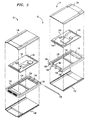
- FIG. 4 illustrates an exploded view of folding electronic card assembly 10.
- Section 12 of the electronic card assembly comprises frame section 50.
- Frame section 50 has connector 18 at one end and outer hinge sections 52 at an opposite end.
- Connector 18 is used to provide an electrical interface to a mating connector within an external device such as a portable computer.
- Connector 18 is in electrical contact with circuit card 54 via contacts 56.
- Circuit card 54 is received by frame 50 and is supported by ledge 58.
- Card 54 can include any variety of electronic components 60 that are required to support the function that the PCMCIA device is to perform. These functions can include providing extra memory, extra programming, a modem or a facsimile.
- Outer hinge sections 52 are connected to inner hinge sections 64 of frame 66 using pin 68.
- Hinge sections 52 and 64 are assembled to form hinge 16 by placing inner hinge sections 64 between outer hinge sections 52 so that pin holes 70 are co-linear. Pin 68 is inserted through pin holes 70 to provide a rotational axis. Hinge sections 52 and 64 may include stops 72 and 74, respectively. Stops 72 and 74 interact to restrict the range of rotation of hinge 16, and thereby limit the maximum angle of separation between sections 12 and 14.
- Circuit card 76 is received by frame 66 and is supported by ledge 78.
- Circuit card 76 can include battery 80, antenna 82, infra-red transceiver 84, transmit/receive electronics 86 and/or other components that perform functions such as interfacing to a cellular communications system. It is also possible to attach antenna 82 to frame 66, or to fabricate frame 66 with antenna 82 embedded in the material composing frame 66.
- the components on circuit cards 54 and 76 can be placed on either of the two cards; however, it is preferable to place antenna 82 and/or transceiver 84 in a section that is not inserted into a PCMCIA slot. Flex circuit or flex cable 88 is used to establish an electrical connection between card 54 and card 76.
- Contacts 90 of flex circuit 88 are connected to contacts 92 of card 76, and contacts 94 of flex circuit 88 are connected to contacts 95 of card 54. This establishes a flexible electrical interface between cards 54 and 76. It is desirable to use a flex circuit or flex cable that has a width that allows it to fit between hinge sections 64.
- Lids 96 and 98 are attached to the upper and lower perimeters, respectively, of frame 50 using an adhesive.
- the lids protect circuit card 54 and its associated electronic components.
- lids 100 and 102 are attached to the upper and lower perimeters of frame 66 using an adhesive. If antenna 82 is included in section 14, lids 100 and 102 should be should be transparent to the frequencies that antenna 82 is designed to receive and/or transmit. If infra-red transceiver 84 is included in section 14, the portions of lids 100 and 102 that cover transceiver 84 should be transparent to infra-red energy.
- FIG. 5 illustrates an embodiment of the present invention with a slidable contact which replaces flex circuit or flex cable 88, and connector 118 which provides an additional electrical interface to the assembly.
- Frame 122 includes hinge section 124 and frame 120 includes hinge sections 126.
- Hinge section 124 fits between hinge sections 126 so that pin holes 128 are co-linear.
- the two hinge sections are connected by inserting pin 130 through pin holes 128 while the pin holes are in a co-linear relationship.
- Circuit card 132 is received by frame 122 and is supported by ledge 134. Electrical contacts 136 of card 132 make electrical contact with conductive strips 138. conductive strips 138 extend around the outer circumference of hinge section 124.
- conductive strips 138 make electrical contact with j-shaped contacts 140.
- j-shaped contacts 140 slide along conductive strips 138 to maintain electrical contact.
- Card 142 has electrical contacts 144 which make electrical contact with j-shaped contacts 140 when card 142 is received by frame 120.
- Card 142 is supported by ledge 144 of frame 120.
- the combination of contacts 136, conductive strips 138, j-shaped contacts 140 and contacts 144 maintain an electrical interface between cards 132 and 142.
- Connector 118 of frame 120 provides an additional electrical interface to the assembly via contacts 145 of card 142.
- lids 146, 148, 150 and 15 are attached to the frames with an adhesive.
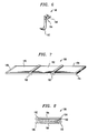
- FIG. 6 illustrates a cross-section of j-shaped contact 140.
- Curved section 162 of j-shaped contact 140 makes electrical contact with conductive strip 138 of hinge section 124 when hinge sections 124 and 126 are joined by pin 130.
- Bracket section 164 of contact 140 fits tightly over ridge 166 of frame 120, and extension 168 of j-shape contact 140 makes electrical contact with contact 144 of card 142.
- FIG. 7 illustrates another embodiment of the present invention where there are three sections composing a folding electronic card assembly.
- Sections 180, 182 and 184 compose folding electronic card assembly 186.
- Connector 188 is used to interface to a mating connector within an external device such as a portable computer.
- Hinge section 190 connects sections 180 and 182 so that they can rotate about an axis through hinge 190.
- Hinge 192 interconnects sections 182 and 184 so that they may rotate about an axis through hinge 192. It is also possible to include connector 194 on one end of section 184 to provide an interface between electronic folding card assembly 186 and other devices. It is also possible to place connector 194 or additional connectors at any convenient location on assembly 186.
- FIG. 8 illustrates assembly 186 in a partially folded or closed position.
- Section 182 has been rotated using hinge 190 so that section 182 is nearly parallel and adjacent to section 180.
- section 184 has been rotated using hinge 192 so that section 184 is nearly parallel and adjacent to section 182.
Landscapes
- Engineering & Computer Science (AREA)
- Theoretical Computer Science (AREA)
- Physics & Mathematics (AREA)
- General Physics & Mathematics (AREA)
- Computer Hardware Design (AREA)
- Microelectronics & Electronic Packaging (AREA)
- General Engineering & Computer Science (AREA)
- Computer Networks & Wireless Communication (AREA)
- Human Computer Interaction (AREA)
- Telephone Set Structure (AREA)
- Credit Cards Or The Like (AREA)
- Transceivers (AREA)
Claims (10)
- Dispositif à carte électronique pliable enfichable, comprenant :une première section (12) ayant un composant (60) électronique;une seconde section (14) ayant un composant (86) électronique supplémentaire;des premiers moyens (18) connecteur pour réaliser une interface électrique avec le dispositif à carte électronique; etdes moyens (16) charnières pour connecter la première section (12) et la seconde section (14) de façon que ces sections puissent être déplacées entre une position ouverte et une position fermée.
- Dispositif à carte électronique pliable enfichable selon la revendication 1, comprenant en outre des moyens (88) conducteurs souples pour réaliser une interface électrique entre les première et seconde sections.
- Dispositif à carte électronique pliable enfichable selon la revendication 1, comprenant en outre des moyens (140) à contact coulissant pour réaliser une interface électrique entre les première et seconde sections.
- Dispositif à carte électronique pliable enfichable selon la revendication 1, comprenant en outre une batterie (80).
- Dispositif à carte électronique pliable enfichable, comprenant :une première section (180) ayant un premier composant électronique;une seconde section (182) ayant un second composant électronique;une troisième section (184) ayant un troisième composant électronique;des premiers moyens (188) connecteurs pour réaliser une interface électrique avec le dispositif à carte électronique ;des premiers moyens (190) à charnière pour connecter la première section (180) et la seconde section (182) de façon que la première section (180) et que la seconde section (182) puissent être déplacées entre une première position ouverte et une première position fermée; etdes seconds moyens (192) à charnière pour connecter la seconde section (182) et la troisième section (184), de façon que la seconde section (182) et la troisième section (184) puissent être déplacées entre une seconde position ouverte et une seconde position fermée.
- Dispositif à carte électronique pliable enfichable, comprenant :une première section (12) ayant un composant (60) électronique;une seconde section (14);des moyens (86) d'émission dans la seconde section (14) pour émettre des informations;un premier connecteur (18) dans la première section (12) pour réaliser une interface électrique avec le dispositif à carte électronique; etdes moyens (16) à charnière pour connecter la première section (12) et la seconde section (14) de façon que ces sections puissent être déplacées entre une position ouverte et une position fermée.
- Dispositif à carte électronique pliable enfichable selon la revendication 6, comprenant en outre des moyens (88) conducteurs souples pour réaliser une interface électrique entre les première et seconde sections.
- Dispositif à carte électronique pliable enfichable selon la revendication 6, comprenant en outre des moyens (140) à contact coulissant pour réaliser une interface électrique entre les première et seconde sections.
- Dispositif à carte électronique pliable enfichable selon la revendication 6, dans lequel les moyens (86) d'émission comprennent une antenne (82).
- Dispositif à carte électronique pliable enfichable selon la revendication 6, dans lequel les moyens (86) d'émission comprennent un émetteur-récepteur infrarouge (84) .
Applications Claiming Priority (2)
| Application Number | Priority Date | Filing Date | Title |
|---|---|---|---|
| US11603 | 1993-02-01 | ||
| US08/011,603 US5373149A (en) | 1993-02-01 | 1993-02-01 | Folding electronic card assembly |
Publications (2)
| Publication Number | Publication Date |
|---|---|
| EP0610025A1 EP0610025A1 (fr) | 1994-08-10 |
| EP0610025B1 true EP0610025B1 (fr) | 1996-06-19 |
Family
ID=21751148
Family Applications (1)
| Application Number | Title | Priority Date | Filing Date |
|---|---|---|---|
| EP94300583A Expired - Lifetime EP0610025B1 (fr) | 1993-02-01 | 1994-01-26 | Carte electronique pliable |
Country Status (5)
| Country | Link |
|---|---|
| US (1) | US5373149A (fr) |
| EP (1) | EP0610025B1 (fr) |
| JP (1) | JPH06282703A (fr) |
| CA (1) | CA2112174C (fr) |
| DE (1) | DE69400248T2 (fr) |
Families Citing this family (146)
| Publication number | Priority date | Publication date | Assignee | Title |
|---|---|---|---|---|
| US5708833A (en) | 1993-04-27 | 1998-01-13 | Norand Corporation | Antenna cap, antenna connectors and telephone line connectors for computer devices utilizing radio and modem cards |
| US7537167B1 (en) | 1993-08-31 | 2009-05-26 | Broadcom Corporation | Modular, portable data processing terminal for use in a radio frequency communication network |
| US7383038B2 (en) * | 1990-01-18 | 2008-06-03 | Broadcom Corporation | Modular, portable data processing terminal for use in a radio frequency communication network |
| JPH04329415A (ja) * | 1991-04-30 | 1992-11-18 | Fujitsu Ltd | カード型入出力インタフェース装置及びシステム |
| US6266017B1 (en) * | 1992-04-08 | 2001-07-24 | 3Com Corporation | Retractable antenna system |
| US5799067A (en) * | 1992-06-29 | 1998-08-25 | Elonex I.P. Holdings Ltd. | Smart phone integration with computer systems |
| US5963872A (en) * | 1993-03-04 | 1999-10-05 | Telefonaktiebolaget Lm Ericsson (Publ) | Electronic equipment audio system |
| US6016432A (en) * | 1993-03-04 | 2000-01-18 | Telefonaktiebolaget L/M Ericsson (Publ) | Electronic metering equipment system |
| US5905947A (en) * | 1993-03-04 | 1999-05-18 | Telefonaktiebolaget Lm Ericsson | Electronic audio system capable of communicating data signals over wireless networks |
| US5890074A (en) * | 1993-03-04 | 1999-03-30 | Telefonaktiebolaget L M Ericsson | Modular unit headset |
| AU690099B2 (en) * | 1993-03-04 | 1998-04-23 | Telefonaktiebolaget Lm Ericsson (Publ) | Modular radio communications system |
| US6928302B1 (en) * | 1993-04-27 | 2005-08-09 | Broadcom Corporation | Radio card having independent antenna interface supporting antenna diversity |
| US7119750B2 (en) * | 1993-04-27 | 2006-10-10 | Broadcom Corporation | Radio transceiver card communicating in a plurality of frequency bands |
| US7469150B2 (en) * | 1993-04-27 | 2008-12-23 | Broadcom Corporation | Radio card having independent antenna interface supporting antenna diversity |
| GB2277841A (en) * | 1993-05-06 | 1994-11-09 | Plessey Semiconductors Ltd | Plug in transmitter/receiver for LAN |
| US7853254B2 (en) * | 1993-08-31 | 2010-12-14 | Broadcom Corp. | Modular, portable data processing terminal for use in a radio frequency communication network |
| US5887145A (en) * | 1993-09-01 | 1999-03-23 | Sandisk Corporation | Removable mother/daughter peripheral card |
| US7137011B1 (en) * | 1993-09-01 | 2006-11-14 | Sandisk Corporation | Removable mother/daughter peripheral card |
| CA2149016C (fr) * | 1993-09-15 | 2005-07-12 | Ericsson Inc. | Systemes d'alimentation de modules enfichables |
| FR2714236B1 (fr) * | 1993-12-17 | 1996-01-26 | Telemecanique | Module additif pour variateur de vitesse. |
| US6295031B1 (en) | 1993-12-23 | 2001-09-25 | Symbol Technologies, Inc. | Memory card assembly having an integral antenna |
| US5519577A (en) * | 1993-12-23 | 1996-05-21 | Symbol Technologies, Inc. | Spread spectrum radio incorporated in a PCMCIA Type II card holder |
| US5537293A (en) * | 1993-12-28 | 1996-07-16 | Nec Corporation | IC card having an electronic apparatus |
| WO1995022183A1 (fr) * | 1994-02-10 | 1995-08-17 | Elonex Technologies, Inc. | Telephone intelligent |
| JP2713155B2 (ja) * | 1994-03-15 | 1998-02-16 | 日本電気株式会社 | Pcカード一体型電子機器 |
| FI102495B1 (fi) * | 1994-03-16 | 1998-12-15 | Nokia Mobile Phones Ltd | Luku/tulostuslaite |
| US5606732A (en) * | 1994-04-26 | 1997-02-25 | Rockwell International Corporation | Direct connect radio and antenna assembly |
| JPH0823149A (ja) * | 1994-05-06 | 1996-01-23 | Seiko Epson Corp | 半導体装置及びその製造方法 |
| JPH07321726A (ja) | 1994-05-20 | 1995-12-08 | Fujitsu Ltd | Icカード型無線通信装置 |
| GB2290923A (en) * | 1994-07-02 | 1996-01-10 | Ghazala Shaheen Jamil Malik | Circuit board to facilitate connection of a computer to a mobile phone system |
| US5463531A (en) * | 1994-07-05 | 1995-10-31 | Motorola, Inc. | PCMCIA electronics housing |
| JP2589963B2 (ja) * | 1994-09-07 | 1997-03-12 | インターナショナル・ビジネス・マシーンズ・コーポレイション | 携帯型情報処理装置のための無線通信装置 |
| US5621363A (en) * | 1994-10-03 | 1997-04-15 | Motorola, Inc. | Modem having an electromagnetic shield for a controller |
| JP2723059B2 (ja) * | 1994-10-31 | 1998-03-09 | 日本電気株式会社 | 折り畳み式データ通信装置 |
| USD368267S (en) | 1994-11-10 | 1996-03-26 | Motorola, Inc. | Protective cover for a PCMCIA radio modem card |
| GB9422838D0 (en) * | 1994-11-11 | 1995-01-04 | Plessey Semiconductors Ltd | Conformal antenna for wireless local area network transceivers |
| JP2959666B2 (ja) * | 1994-11-15 | 1999-10-06 | インターナショナル・ビジネス・マシーンズ・コーポレイション | 無線通信装置 |
| MY114912A (en) * | 1994-12-22 | 2003-02-28 | Ibm | Removable electronic subassembly with a compressible shock absorbing device |
| EP0722138A1 (fr) * | 1995-01-04 | 1996-07-17 | International Business Machines Corporation | Système basé sur un module pour ordinateurs portables et non-portables |
| DE19601949B4 (de) * | 1995-01-13 | 2004-08-12 | Stratos Lightwave, Inc. (n.d.Ges.d. Staates Delaware), Harwood Heights | System zum Schaffen einer statischen Entladung und einer elektromagnetischen Abschirmung |
| GB9501506D0 (en) * | 1995-01-26 | 1995-03-15 | Symbionics Dev Ltd | Antennas |
| US5619396A (en) * | 1995-02-21 | 1997-04-08 | Intel Corporation | Modular PCMCIA card |
| US5848298A (en) * | 1995-02-21 | 1998-12-08 | Intel Corporation | System having two PC cards in a hinged carrying case with battery compartment within in the hinge section |
| US5667390A (en) * | 1995-03-06 | 1997-09-16 | Hon Hai Precision Ind. Co., Ltd. | I/O card and its associated cable harness assembly |
| USRE39052E1 (en) | 1995-03-07 | 2006-03-28 | Tao Logic Systems Llc | System and method for expansion of a computer |
| EP0765502B1 (fr) | 1995-03-07 | 2005-01-26 | Mobility Electronics, Inc. | Systeme et procede d'extension d'un ordinateur |
| US5918163A (en) * | 1995-03-31 | 1999-06-29 | Compaq Computer Corporation | Electronic card assembly having a retractable antenna |
| US5657028A (en) * | 1995-03-31 | 1997-08-12 | Nokia Moblie Phones Ltd. | Small double C-patch antenna contained in a standard PC card |
| US5668654A (en) * | 1995-05-30 | 1997-09-16 | The Whitaker Corporation | Package for an infrared communications adapter |
| US5627550A (en) * | 1995-06-15 | 1997-05-06 | Nokia Mobile Phones Ltd. | Wideband double C-patch antenna including gap-coupled parasitic elements |
| DE19523916A1 (de) * | 1995-06-30 | 1997-01-02 | Telefunken Microelectron | Chip-Karte |
| US5812371A (en) * | 1995-07-25 | 1998-09-22 | Compal Electronics, Inc. | Orientation-adjustable infrared transceiver used in a notebook type computer |
| US5583521A (en) * | 1995-08-11 | 1996-12-10 | Gec Plessey Semiconductors, Inc. | Compact antenna for portable microwave radio |
| US5646635A (en) * | 1995-08-17 | 1997-07-08 | Centurion International, Inc. | PCMCIA antenna for wireless communications |
| USD379983S (en) * | 1995-09-28 | 1997-06-17 | Sony Corporation | Wireless telephone |
| US6618013B1 (en) | 1996-01-16 | 2003-09-09 | 3Com Corporation | Retractable antenna assembly |
| USD382297S (en) * | 1996-02-28 | 1997-08-12 | Hewlett-Packard Company | Infrared communication port for a portable inkjet printer |
| US5680144A (en) * | 1996-03-13 | 1997-10-21 | Nokia Mobile Phones Limited | Wideband, stacked double C-patch antenna having gap-coupled parasitic elements |
| US5941965A (en) * | 1996-05-16 | 1999-08-24 | Electronics Accessory Specialists International, Inc. | Universal docking station |
| KR100213373B1 (ko) * | 1996-05-28 | 1999-08-02 | 이형도 | 무선 랜 카드용 안테나 |
| US6697415B1 (en) * | 1996-06-03 | 2004-02-24 | Broadcom Corporation | Spread spectrum transceiver module utilizing multiple mode transmission |
| JPH103312A (ja) * | 1996-06-17 | 1998-01-06 | Fanuc Ltd | 数値制御装置の管理方法 |
| US6005700A (en) * | 1996-06-26 | 1999-12-21 | Aironet Wireless Communications, Inc. | Computer peripheral device with detachable portion and light display |
| NL1003693C2 (nl) * | 1996-07-26 | 1998-01-28 | Nederland Ptt | Connector gevormd als chipkaart, inrichting voor samenwerking daarmee en inrichting voorzien daarvan. |
| KR100408264B1 (ko) * | 1996-08-21 | 2004-04-14 | 삼성전자주식회사 | 컴퓨터 |
| FR2755566B1 (fr) * | 1996-11-04 | 1998-12-11 | Alsthom Cge Alcatel | Modem radio equipe d'un lecteur de carte a memoire |
| US6424722B1 (en) * | 1997-01-13 | 2002-07-23 | Micro Ear Technology, Inc. | Portable system for programming hearing aids |
| US7787647B2 (en) | 1997-01-13 | 2010-08-31 | Micro Ear Technology, Inc. | Portable system for programming hearing aids |
| US6449662B1 (en) | 1997-01-13 | 2002-09-10 | Micro Ear Technology, Inc. | System for programming hearing aids |
| US5978379A (en) | 1997-01-23 | 1999-11-02 | Gadzoox Networks, Inc. | Fiber channel learning bridge, learning half bridge, and protocol |
| FI102927B1 (fi) * | 1997-02-14 | 1999-03-15 | Nokia Mobile Phones Ltd | Kommunikointiyksikkö, antenni ja menetelmä antennin liittämiseksi |
| US6031503A (en) * | 1997-02-20 | 2000-02-29 | Raytheon Company | Polarization diverse antenna for portable communication devices |
| USD396044S (en) | 1997-03-04 | 1998-07-14 | Northrop Grumman Corporation | Modem |
| US5987547A (en) * | 1997-03-31 | 1999-11-16 | Texas Instruments Incorporated | Network computer with interchangeable hard drive and data transceiver |
| US6002946A (en) | 1997-04-14 | 1999-12-14 | Motorola, Inc. | Handheld device having an optical data reader |
| US5959979A (en) * | 1997-05-05 | 1999-09-28 | Northrop Grumman Corporation | Half-duplex communication system for telemetry modems |
| JP3393789B2 (ja) * | 1997-05-20 | 2003-04-07 | インターナショナル・ビジネス・マシーンズ・コーポレーション | 情報処理端末 |
| US6032866A (en) * | 1997-09-10 | 2000-03-07 | Motorola, Inc. | Foldable apparatus having an interface |
| WO1999014993A2 (fr) * | 1997-09-15 | 1999-03-25 | Berg Technology, Inc. | Carte electronique a extension rf |
| US6115242A (en) * | 1997-10-24 | 2000-09-05 | Advanced Micro Devices, Inc. | Chip chassis including a micro-backplane for receiving and connecting a plurality of computer chips |
| US7248626B2 (en) | 1997-12-05 | 2007-07-24 | Paradyne Corporation | System and method of communication via embedded modulation |
| US9432172B2 (en) | 1997-12-05 | 2016-08-30 | Rembrandt Wireless Technologies, Lp | System and method of communication using at least two modulation methods |
| US6366863B1 (en) | 1998-01-09 | 2002-04-02 | Micro Ear Technology Inc. | Portable hearing-related analysis system |
| FI980300L (fi) * | 1998-02-10 | 1999-08-11 | Nokia Mobile Phones Ltd | Korttimainen langaton viestin |
| JP3192402B2 (ja) * | 1998-04-14 | 2001-07-30 | 日本圧着端子製造株式会社 | Pcカード用フレームキットおよびpcカードならびにpcカードの製造方法 |
| US7734852B1 (en) | 1998-08-06 | 2010-06-08 | Ahern Frank W | Modular computer system |
| US7430171B2 (en) | 1998-11-19 | 2008-09-30 | Broadcom Corporation | Fibre channel arbitrated loop bufferless switch circuitry to increase bandwidth without significant increase in cost |
| US6522299B2 (en) | 1999-04-08 | 2003-02-18 | Cypress Semiconductor Corp. | PC card retractable antenna |
| FI111420B (fi) | 1999-05-07 | 2003-07-15 | Nokia Corp | Elektroniikkalaitteen laajennuskortin antennirakenne |
| US6897697B2 (en) | 1999-06-28 | 2005-05-24 | Broadcom Corporation | Current-controlled CMOS circuit using higher voltage supply in low voltage CMOS process |
| US6911855B2 (en) | 1999-06-28 | 2005-06-28 | Broadcom Corporation | Current-controlled CMOS circuit using higher voltage supply in low voltage CMOS process |
| US6424194B1 (en) | 1999-06-28 | 2002-07-23 | Broadcom Corporation | Current-controlled CMOS logic family |
| US6424177B1 (en) * | 1999-06-28 | 2002-07-23 | Broadcom Corporation | Universal single-ended parallel bus |
| US6418325B1 (en) | 1999-07-12 | 2002-07-09 | Motorola, Inc. | Handheld device having an optical data reader |
| DE19934837A1 (de) * | 1999-07-24 | 2001-01-25 | Bosch Gmbh Robert | Adapterkarte, Naviagtionsgerät und Funkgerät |
| US6366450B1 (en) * | 1999-12-09 | 2002-04-02 | Gateway, Inc. | Hideaway integrated docking cradle |
| EP1252799B2 (fr) | 2000-01-20 | 2022-11-02 | Starkey Laboratories, Inc. | Procédé et appareil pour l'adaptation des prothèses auditives |
| US6295197B1 (en) | 2000-01-25 | 2001-09-25 | Dell Usa, L.P. | Wireless communication apparatus |
| US6963757B1 (en) | 2000-01-25 | 2005-11-08 | Dell Usa, L.P. | Wireless communication apparatus |
| US6340899B1 (en) | 2000-02-24 | 2002-01-22 | Broadcom Corporation | Current-controlled CMOS circuits with inductive broadbanding |
| KR20010092569A (ko) * | 2000-03-22 | 2001-10-26 | 이은복 | 탈착 가능한 전자 기기를 포함하는 이동 전화기 |
| US6594719B1 (en) | 2000-04-19 | 2003-07-15 | Mobility Electronics Inc. | Extended cardbus/pc card controller with split-bridge ™technology |
| FR2812167B1 (fr) * | 2000-07-19 | 2004-09-10 | Fci Besancon Sa | Boitier muni d'une extension d'antenne pour carte electronique et procede d'assemblage du boitier |
| US6545643B1 (en) | 2000-09-08 | 2003-04-08 | 3Com Corporation | Extendable planar diversity antenna |
| GB0024083D0 (en) * | 2000-10-02 | 2000-11-15 | Ubinetics Ltd | Peripheral device for a computer |
| KR20020027732A (ko) * | 2000-10-04 | 2002-04-15 | 윤종용 | 디스크 드라이브 |
| US6824066B2 (en) * | 2000-10-06 | 2004-11-30 | Leon H. Weyant | Electronic access security key card pamphlet |
| US7050306B1 (en) * | 2000-10-17 | 2006-05-23 | Spx Corporation | Plug-in module for portable computing device |
| CA2357236C (fr) * | 2000-10-17 | 2011-09-06 | Spx Development Corporation | Module enfichable pour dispositif d'informatique portatif |
| US6573868B2 (en) | 2001-02-28 | 2003-06-03 | 3Com Corporation | Retractable antenna for electronic devices |
| US6556170B2 (en) | 2001-04-02 | 2003-04-29 | Fci Americas Technology, Inc. | Retractable and rotatable antenna for an electronic card |
| USD470845S1 (en) | 2001-04-17 | 2003-02-25 | Samsung Electronics Co., Ltd. | Wireless keyboard for portable telephone |
| US6864558B2 (en) | 2001-05-17 | 2005-03-08 | Broadcom Corporation | Layout technique for C3MOS inductive broadbanding |
| DE20108778U1 (de) * | 2001-05-25 | 2001-08-02 | Mannesmann VDO AG, 60388 Frankfurt | Gehäuse für ein in einem Fahrzeug verwendbares Gerät zur automatischen Ermittlung von Straßenbenutzungsgebühren |
| JP2003006603A (ja) * | 2001-06-26 | 2003-01-10 | Toshiba Corp | Icカードおよびこのicカードを有する情報処理装置 |
| US7239636B2 (en) | 2001-07-23 | 2007-07-03 | Broadcom Corporation | Multiple virtual channels for use in network devices |
| US6807432B2 (en) * | 2001-08-08 | 2004-10-19 | Hong-Wen Hwang | Wireless transmission network card |
| DE20114246U1 (de) | 2001-08-29 | 2001-10-31 | Siemens AG, 80333 München | Antennenvorrichtung zum Anschluss an einen Rechner |
| JP2003108955A (ja) * | 2001-09-27 | 2003-04-11 | Toshiba Corp | Pcカードおよびこのpcカードを備える情報処理装置 |
| US6624699B2 (en) | 2001-10-25 | 2003-09-23 | Broadcom Corporation | Current-controlled CMOS wideband data amplifier circuits |
| US7295555B2 (en) | 2002-03-08 | 2007-11-13 | Broadcom Corporation | System and method for identifying upper layer protocol message boundaries |
| US7346701B2 (en) | 2002-08-30 | 2008-03-18 | Broadcom Corporation | System and method for TCP offload |
| US7934021B2 (en) | 2002-08-29 | 2011-04-26 | Broadcom Corporation | System and method for network interfacing |
| US7411959B2 (en) | 2002-08-30 | 2008-08-12 | Broadcom Corporation | System and method for handling out-of-order frames |
| US8180928B2 (en) | 2002-08-30 | 2012-05-15 | Broadcom Corporation | Method and system for supporting read operations with CRC for iSCSI and iSCSI chimney |
| US7313623B2 (en) | 2002-08-30 | 2007-12-25 | Broadcom Corporation | System and method for TCP/IP offload independent of bandwidth delay product |
| US6822878B2 (en) * | 2002-10-09 | 2004-11-23 | Hewlett-Packard Development Company, L.P. | Circuit board support arrangement, method, and method for using the same |
| TWI264144B (en) * | 2002-12-10 | 2006-10-11 | Hon Hai Prec Ind Co Ltd | Panel antenna and the method for installing the same |
| TW200410122A (en) * | 2002-12-13 | 2004-06-16 | Apacer Technology Inc | Direct coupling type serial transmitting interface card |
| US7715867B2 (en) * | 2003-09-26 | 2010-05-11 | Lenovo (Beijing) Limited | Mobile communication terminal and wireless communication module thereof |
| US6939182B1 (en) * | 2004-04-20 | 2005-09-06 | C-One Technology Corporation | Fool-proof mechanism for memory card |
| US7711377B2 (en) | 2004-06-10 | 2010-05-04 | Qualcomm Incorporated | Efficient paging in a wireless communication system |
| JP2006340367A (ja) * | 2005-06-02 | 2006-12-14 | Behavior Tech Computer Corp | 内蔵式アンテナ及びコネクタを備える無線送信装置 |
| US7598811B2 (en) | 2005-07-29 | 2009-10-06 | Broadcom Corporation | Current-controlled CMOS (C3MOS) fully differential integrated wideband amplifier/equalizer with adjustable gain and frequency response without additional power or loading |
| US7362174B2 (en) | 2005-07-29 | 2008-04-22 | Broadcom Corporation | Current-controlled CMOS (C3MOS) wideband input data amplifier for reduced differential and common-mode reflection |
| US7598788B2 (en) | 2005-09-06 | 2009-10-06 | Broadcom Corporation | Current-controlled CMOS (C3MOS) fully differential integrated delay cell with variable delay and high bandwidth |
| US7554812B2 (en) * | 2005-10-11 | 2009-06-30 | Apple Inc. | Structural support for portable electronic devices |
| US7623357B2 (en) * | 2005-11-02 | 2009-11-24 | Symbol Technologies, Inc. | Card holder arrangement for circuit assembly |
| US20070246545A1 (en) * | 2006-04-25 | 2007-10-25 | Ceramate Technical Co., Ltd. | Receiving module with a built-in antenna |
| CA2601662A1 (fr) | 2006-09-18 | 2008-03-18 | Matthias Mullenborn | Interface sans fil pour programmer des dispositifs d'aide auditive |
| US7990724B2 (en) | 2006-12-19 | 2011-08-02 | Juhasz Paul R | Mobile motherboard |
| CN201238309Y (zh) * | 2008-08-13 | 2009-05-13 | 深圳华为通信技术有限公司 | 一种通信设备 |
| JP2010211700A (ja) * | 2009-03-12 | 2010-09-24 | Panasonic Corp | 半導体カード |
| CN106650895A (zh) * | 2016-12-23 | 2017-05-10 | 安徽大鸿智能科技有限公司 | 折叠信息存储卡片 |
| DE112022007196T5 (de) * | 2022-07-20 | 2025-04-17 | Mitsubishi Electric Corporation | Elektronische Vorrichtung |
| EP4738188A1 (fr) * | 2024-10-30 | 2026-05-06 | Giesecke+Devrient ePayments GmbH | Carte à puce ainsi que procédé de fabrication et kit de construction pour une carte à puce comprenant une section d'extension |
Family Cites Families (6)
| Publication number | Priority date | Publication date | Assignee | Title |
|---|---|---|---|---|
| JPH0696356B2 (ja) * | 1986-03-17 | 1994-11-30 | 三菱電機株式会社 | 薄型半導体カード |
| US4885430A (en) * | 1986-05-29 | 1989-12-05 | Hewlett-Packard Company | Flexible printed circuit assembly with torsionly rotated conductors |
| JPS643966U (fr) * | 1987-06-26 | 1989-01-11 | ||
| US5061845A (en) * | 1990-04-30 | 1991-10-29 | Texas Instruments Incorporated | Memory card |
| JP2872793B2 (ja) * | 1990-10-01 | 1999-03-24 | 株式会社日立製作所 | Icカード |
| JP4133391B2 (ja) * | 2002-02-06 | 2008-08-13 | 山佐株式会社 | スロットマシン |
-
1993
- 1993-02-01 US US08/011,603 patent/US5373149A/en not_active Expired - Lifetime
- 1993-12-22 CA CA002112174A patent/CA2112174C/fr not_active Expired - Fee Related
-
1994
- 1994-01-26 EP EP94300583A patent/EP0610025B1/fr not_active Expired - Lifetime
- 1994-01-26 DE DE69400248T patent/DE69400248T2/de not_active Expired - Fee Related
- 1994-01-31 JP JP6025907A patent/JPH06282703A/ja active Pending
Also Published As
| Publication number | Publication date |
|---|---|
| CA2112174A1 (fr) | 1994-08-02 |
| US5373149A (en) | 1994-12-13 |
| CA2112174C (fr) | 1996-07-16 |
| DE69400248D1 (de) | 1996-07-25 |
| EP0610025A1 (fr) | 1994-08-10 |
| DE69400248T2 (de) | 1996-11-28 |
| JPH06282703A (ja) | 1994-10-07 |
Similar Documents
| Publication | Publication Date | Title |
|---|---|---|
| US5373149A (en) | Folding electronic card assembly | |
| US6870733B2 (en) | Standardized RF module insert for a portable electronic processing device | |
| US5440449A (en) | Wireless communication connector and module for notebook personal computers | |
| EP3355160B1 (fr) | Élément de recouvrement, ensemble boîtier et dispositif électronique | |
| EP1381207B1 (fr) | Terminal mobile avec un module doté d'objectif de caméra monté en manière rotatif | |
| US6049450A (en) | Portable computer on which a communication device can be mounted | |
| JP3516329B2 (ja) | 無線アンテナ及びモバイル・コンピュータ | |
| US6473296B2 (en) | Information processing device | |
| EP2124297B1 (fr) | Carte de données | |
| JPH08279027A (ja) | 無線通信カード | |
| EP1202378B1 (fr) | Antenne rétractable avec systeme de blocage en position pour carte d'ordinateur portable | |
| US20070076387A1 (en) | Usb device with plastic housing having integrated plastic plug shell | |
| US20080166902A1 (en) | Dongle device | |
| US20100279694A1 (en) | Display panel structure, electronic device using the same, and mobile information equipment | |
| EP0696855A3 (fr) | Module enfichable sans fil pour ordinateur portable | |
| US6419506B2 (en) | Combination miniature cable connector and antenna | |
| EP2302568A2 (fr) | Dispositif d'antenne | |
| CN1773769B (zh) | 用于便携式终端的天线装置 | |
| US6766402B1 (en) | computer in which an optional unit is installable | |
| US6594506B1 (en) | Antenna structure in an expansion card for an electronic device | |
| EP1125368B1 (fr) | Logement de batterie pour modem a carte pcmcia avec antenne | |
| GB2277841A (en) | Plug in transmitter/receiver for LAN | |
| GB2357190A (en) | Extending antenna on/off switch; reconfigurable wireless device | |
| US20050049014A1 (en) | Wireless local area network device | |
| US20060046779A1 (en) | Method and apparatus for providing enhanced functionality for a mobile communication device |
Legal Events
| Date | Code | Title | Description |
|---|---|---|---|
| PUAI | Public reference made under article 153(3) epc to a published international application that has entered the european phase |
Free format text: ORIGINAL CODE: 0009012 |
|
| AK | Designated contracting states |
Kind code of ref document: A1 Designated state(s): DE FR GB IT |
|
| 17P | Request for examination filed |
Effective date: 19950126 |
|
| 17Q | First examination report despatched |
Effective date: 19950818 |
|
| GRAH | Despatch of communication of intention to grant a patent |
Free format text: ORIGINAL CODE: EPIDOS IGRA |
|
| GRAH | Despatch of communication of intention to grant a patent |
Free format text: ORIGINAL CODE: EPIDOS IGRA |
|
| GRAA | (expected) grant |
Free format text: ORIGINAL CODE: 0009210 |
|
| AK | Designated contracting states |
Kind code of ref document: B1 Designated state(s): DE FR GB IT |
|
| REF | Corresponds to: |
Ref document number: 69400248 Country of ref document: DE Date of ref document: 19960725 |
|
| ET | Fr: translation filed | ||
| ITF | It: translation for a ep patent filed | ||
| PGFP | Annual fee paid to national office [announced via postgrant information from national office to epo] |
Ref country code: FR Payment date: 19970115 Year of fee payment: 4 |
|
| PGFP | Annual fee paid to national office [announced via postgrant information from national office to epo] |
Ref country code: DE Payment date: 19970117 Year of fee payment: 4 |
|
| PLBE | No opposition filed within time limit |
Free format text: ORIGINAL CODE: 0009261 |
|
| STAA | Information on the status of an ep patent application or granted ep patent |
Free format text: STATUS: NO OPPOSITION FILED WITHIN TIME LIMIT |
|
| 26N | No opposition filed | ||
| PG25 | Lapsed in a contracting state [announced via postgrant information from national office to epo] |
Ref country code: GB Free format text: LAPSE BECAUSE OF NON-PAYMENT OF DUE FEES Effective date: 19980126 |
|
| PG25 | Lapsed in a contracting state [announced via postgrant information from national office to epo] |
Ref country code: FR Free format text: THE PATENT HAS BEEN ANNULLED BY A DECISION OF A NATIONAL AUTHORITY Effective date: 19980131 |
|
| GBPC | Gb: european patent ceased through non-payment of renewal fee |
Effective date: 19980126 |
|
| PG25 | Lapsed in a contracting state [announced via postgrant information from national office to epo] |
Ref country code: DE Free format text: LAPSE BECAUSE OF NON-PAYMENT OF DUE FEES Effective date: 19981001 |
|
| REG | Reference to a national code |
Ref country code: FR Ref legal event code: ST |
|
| PG25 | Lapsed in a contracting state [announced via postgrant information from national office to epo] |
Ref country code: IT Free format text: LAPSE BECAUSE OF NON-PAYMENT OF DUE FEES;WARNING: LAPSES OF ITALIAN PATENTS WITH EFFECTIVE DATE BEFORE 2007 MAY HAVE OCCURRED AT ANY TIME BEFORE 2007. THE CORRECT EFFECTIVE DATE MAY BE DIFFERENT FROM THE ONE RECORDED. Effective date: 20050126 |