EP0610044B1 - Assemblage modulair d'une barrette de raccordement d'un disjoncteur à boíte moulé - Google Patents
Assemblage modulair d'une barrette de raccordement d'un disjoncteur à boíte moulé Download PDFInfo
- Publication number
- EP0610044B1 EP0610044B1 EP94300690A EP94300690A EP0610044B1 EP 0610044 B1 EP0610044 B1 EP 0610044B1 EP 94300690 A EP94300690 A EP 94300690A EP 94300690 A EP94300690 A EP 94300690A EP 0610044 B1 EP0610044 B1 EP 0610044B1
- Authority
- EP
- European Patent Office
- Prior art keywords
- support plate
- strap assembly
- line strap
- brace
- circuit breaker
- Prior art date
- Legal status (The legal status is an assumption and is not a legal conclusion. Google has not performed a legal analysis and makes no representation as to the accuracy of the status listed.)
- Expired - Lifetime
Links
- RYGMFSIKBFXOCR-UHFFFAOYSA-N Copper Chemical compound [Cu] RYGMFSIKBFXOCR-UHFFFAOYSA-N 0.000 description 3
- 229910052802 copper Inorganic materials 0.000 description 3
- 239000010949 copper Substances 0.000 description 3
- 239000004033 plastic Substances 0.000 description 3
- 229910001316 Ag alloy Inorganic materials 0.000 description 2
- 239000000463 material Substances 0.000 description 2
- 239000002991 molded plastic Substances 0.000 description 2
- BQCADISMDOOEFD-UHFFFAOYSA-N Silver Chemical compound [Ag] BQCADISMDOOEFD-UHFFFAOYSA-N 0.000 description 1
- 239000000654 additive Substances 0.000 description 1
- 230000000996 additive effect Effects 0.000 description 1
- 230000002411 adverse Effects 0.000 description 1
- 230000009286 beneficial effect Effects 0.000 description 1
- 238000005219 brazing Methods 0.000 description 1
- 238000010276 construction Methods 0.000 description 1
- 230000005520 electrodynamics Effects 0.000 description 1
- 239000011213 glass-filled polymer Substances 0.000 description 1
- 238000010438 heat treatment Methods 0.000 description 1
- 238000003780 insertion Methods 0.000 description 1
- 230000037431 insertion Effects 0.000 description 1
- 238000011068 loading method Methods 0.000 description 1
- 239000002184 metal Substances 0.000 description 1
- 229910052751 metal Inorganic materials 0.000 description 1
- 238000013021 overheating Methods 0.000 description 1
- 238000000926 separation method Methods 0.000 description 1
- 229910052709 silver Inorganic materials 0.000 description 1
- 239000004332 silver Substances 0.000 description 1
- 238000003466 welding Methods 0.000 description 1
Images


Classifications
-
- H—ELECTRICITY
- H01—ELECTRIC ELEMENTS
- H01H—ELECTRIC SWITCHES; RELAYS; SELECTORS; EMERGENCY PROTECTIVE DEVICES
- H01H71/00—Details of the protective switches or relays covered by groups H01H73/00 - H01H83/00
- H01H71/74—Means for adjusting the conditions under which the device will function to provide protection
- H01H71/7409—Interchangeable elements
-
- H—ELECTRICITY
- H01—ELECTRIC ELEMENTS
- H01H—ELECTRIC SWITCHES; RELAYS; SELECTORS; EMERGENCY PROTECTIVE DEVICES
- H01H9/00—Details of switching devices, not covered by groups H01H1/00 - H01H7/00
- H01H9/30—Means for extinguishing or preventing arc between current-carrying parts
- H01H9/46—Means for extinguishing or preventing arc between current-carrying parts using arcing horns
Definitions
- the present invention relates to a line strap assembly for a molded case circuit breaker according to the preamble of claim 1.
- U.S. Patent 4,754,247 entitled “Molded Case Circuit Breaker Accessory Enclosure” describes a so-called “integrated” circuit breaker that provides both circuit interruption as well as accessory function.
- This Patent should be reviewed for its disclosure of an accessory cover mounted on the circuit breaker cover for providing access to field-installable accessory devices.
- the integrated circuit breaker includes an integrated circuit electronic trip unit which allows one circuit breaker design to be used over a wide range of ampere ratings in combination with a rating plug, also mounted in the circuit breaker cover.
- the electronic trip unit is described within U.S. Patent 4,589,052 and the rating plug is described within U.S. Patent 4,649,455.
- one purpose of the invention is to provide a circuit breaker line strap modular assembly whereby the line strap components are additively combined for each circuit breaker ampere rating.
- line strap assembly for a molded case circuit breaker comprising in combination: an electrically-conductive support plate having means at one end for receiving a line terminal connector; and an electrically-insulative plate having an aperture formed within one end and arranged on a top surface of the support plate; characterized by an arc runner having an offset formed at one end and an upturned tab formed at an opposite end thereof, the offset being arranged within the aperture and the tab being arranged over said insulative plate; and a brace attached to a bottom surface of the support plate providing additional support to the support plate.
- the brace may be U-shaped.
- An integrated circuit breaker 10 is shown in Figure 1 and consists of a molded plastic case 11 to which a molded plastic cover 12 is attached.
- An accessory cover 13 as described in the aforementioned U.S. Patent 4,754,247 is arranged on the top of the cover around the handle slot opening 14 through which the handle operator 15 extends.
- the rating plug 21 is also accessible from the circuit breaker cover to allow the ampere rating of the circuit breaker to be adjusted as described within aforementioned U.S. Patent 4,649,455.
- Electrical connection with an industrial power distribution circuit is made by means by the line terminal lugs 16 that are supported upon a line terminal inset 17 within the line terminal compartments 19 and attached to the threaded opening 35.
- a similar load terminal inset 18 is arranged at the load terminal end, as indicated.
- the line terminal strap 20 electrically connects with the circuit breaker current-carrying components as best seen by now referring to Figure 2.
- the circuit breaker 10 is depicted in Figure 2 with the cover removed to show the circuit breaker operating mechanism 22 which is better described in U.S. Patent 5,004,878 entitled "Molded Case Circuit Breaker Movable Contact Arm Arrangement".
- the circuit current transfers between the line terminal lugs 16 and line terminal straps 20 that are arranged within the line terminal compartments 19 at one end, through the fixed arcing contact 28.
- the fixed contacts transfer current to the movable arcing contacts 25 that are arranged on the movable arcing contact arms 24 and which connect with the load terminal straps 20A and load terminal lugs 16A arranged within the load terminal compartment 31.
- the operating mechanism Upon the occurrence of an overcurrent condition, the operating mechanism lifts the movable arcing contact arms 24 to rapidly separate the movable arcing contacts 25 from the fixed arcing contact 28, and thereby separate the circuit existing between the line and load terminal lugs.
- the current transfers from the fixed main contacts 29 to the fixed arcing contacts 28 and then to the associated arc runners 30.
- the arc that is generated during the contact separation is extinguished in the arc chutes 26 within the arc plates 27.
- the crossbar 23 interconnects each of the three movable arcing contact arms 24 to insure that the contact arms respond simultaneously within the operating mechanism 22.
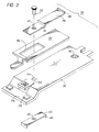
- the line strap 20 is shown in Fig. 3 to consist of a basic support plate 32 of silver-plated copper stock which is formed to an off-set end 34 to which the fixed main contacts 29 of a silver alloy are attached.
- the lanced upper part 33 supports the fixed arcing contact 28 also formed from a silver alloy.
- a thru-hole 44 formed in the support plate locates both the arc runner 30 and the high temperature plastic insulating plate 37 on the support plate 32.
- the off-set end 41 is sized to fit within the rectangular slot 38 and is attached to the support plate 32 by insertion of the screw 52 through the thru-hole 42 in the offset end 41 through the thru-hole 44 and into the threaded opening 45 of the support 43 to trap the plastic plate 37 between the arc runner 30 and the support plate 32.
- the upstanding tab 40 at the end of the arc runner is operationally positioned at one end of the plastic plate 37 and the tongue 39 extending from the opposite end is operationally positioned between the fixed main contacts 29. Since the thickness of the support plate 32 is reduced to approximately fifty percent of the prior art line strap thickness, additional strength must be provided to compensate for the corresponding reduction in the mass of material.
- This support is in the form of a U-shaped support brace 43 formed from a metal plate to define a pair of downwardly depending tabs or legs 46, the bottom of which are co-extensive with the bottom of the off-set end 34 of the support plate 32.
- the threaded opening 45 formed in the support brace is aligned with the thru-holes 42,44 to receive the attachment screw 52.
- the line strap 20 (depicted in Figure 2) includes the fixed arcing contact 28 and fixed main contacts 29.
- a conductive plate 47 consisting of silver-plated copper is attached to a bottom part thereof in place of the U-shaped support brace, described earlier.
- the conductive plate includes an opening 53 oversized to receive the collar 36 extending from the bottom of the thru-hole 35 formed in the line strap support plate 32.
- the conductive plate 47 is attached to the support plate 32 by welding or brazing.
- the conductive plate can also be attached by means of thru-holes 48 in the conductive plate, threaded openings 50 in the support plate and screws 51 to form the higher current line strap 20' shown in Figure 5.
- the screw 52 passes though the thru-hole 42 in the arc runner 30, the thru-hole 44 in the support plate 32 and the threaded opening 49 in the conductive plate 47 to provide further attachment between the conductive plate 47 and the support plate 32.
- the attachment of the conductive plate increases the mass of the line strap such that the support brace 43 of Figure 3 is no longer required.
- a modular line strap assembly having both high and low current capability has herein been described.
- the arrangement of an additive conductive plate allows higher currents to transfer without adverse heating while the absence of the conductive plate allows lower currents without over-heating and at a substantial cost savings.
Landscapes
- Breakers (AREA)
Claims (11)
- Assemblage de barrette de raccordement pour disjoncteur à boítier moulé, comprenant, en combinaison:une plaque de support électriquement conductrice (32) ayant à une première extrémité un moyen pour recevoir un connecteur (29) de bornes de ligne; etune plaque électriquement isolante (37) disposée sur la surface supérieure de la plaque de support (32), et à une extrémité de laquelle est formée une ouverture (38); et caractérisé parun guide (30) d'arc ayant une partie décalée (41) formée à une première extrémité et une languette (40) tournée vers le haut formée à une extrémité opposée de celle-ci, la partie décalée (41) étant disposée dans l'ouverture (38) et la languette (40) étant disposée par-dessus ladite plaque isolante (37); etun renfort (43, 47) fixé à la surface inférieure de la plaque de support (32) assurant un support supplémentaire pour la plaque de support (32).
- Assemblage de barrette de raccordement selon la revendication 1, dans laquelle le renfort (43) est en U.
- Assemblage de barrette de raccordement selon la revendication 1 ou 2, caractérisé par une première ouverture (42) formée dans la partie décalée (41), une deuxième ouverture (44) formée dans la plaque de support (32) et ayant la même extension que la première ouverture (42), et une troisième ouverture (45) formée dans le renfort (43) et ayant la même extension que la première et la deuxième ouvertures (42, 44).
- Assemblage de barrette de raccordement selon la revendication 3, caractérisé par un moyen (52) s'étendant à travers les première, deuxième et troisième ouvertures (42, 44, 45) pour fixer le guide (30) d'arc à la plaque de support (32) et au renfort (43), grâce à quoi la plaque isolante (37) est immobilisée entre le guide (30) d'arc et la plaque de support (32).
- Assemblage de barrette de raccordement selon l'une quelconque des revendications 1 à 4, caractérisé par une partie incisée (33) formée sur la plaque de support (32) et supportant un contact d'arc fixe (28).
- Assemblage de barrette de raccordement selon l'une quelconque des revendications précédentes, caractérisé par une paire de contacts principaux fixes (29) fixés à la plaque de support (32).
- Assemblage de barrette de raccordement selon la revendication 6, caractérisé par une langue (39) formée à une extrémité de la plaque isolante (37) et disposée entre les contacts principaux (29).
- Assemblage de barrette de raccordement selon la revendication 3 où toute revendication dépendant directement ou indirectement de celle-ci, caractérisé en ce que la troisième ouverture (45) comporte un orifice fileté.
- Assemblage de barrette de raccordement selon l'une quelconque des revendications précédentes, caractérisé en ce que le renfort (47) comporte une plaque conductrice.
- Assemblage de barrette de raccordement selon la revendication 9, caractérisé en ce que le renfort (47) est soudé ou brasé sur la plaque de support (32).
- Assemblage de barrette de raccordement selon l'une quelconque des revendications précédentes, caractérisé en ce que la plaque de support (32) comporte à une extrémité une partie décalée (34) et le renfort (43) comporte une paire de languettes (46) en déport vers le bas, le bas de ces languettes (46) ayant la même extension que le bas de la partie décalée (34) de la plaque de support.
Applications Claiming Priority (2)
| Application Number | Priority Date | Filing Date | Title |
|---|---|---|---|
| US08/011,816 US5323130A (en) | 1993-02-01 | 1993-02-01 | Molded case circuit breaker modular line strap assembly |
| US11816 | 1993-02-01 |
Publications (2)
| Publication Number | Publication Date |
|---|---|
| EP0610044A1 EP0610044A1 (fr) | 1994-08-10 |
| EP0610044B1 true EP0610044B1 (fr) | 2000-08-02 |
Family
ID=21752092
Family Applications (1)
| Application Number | Title | Priority Date | Filing Date |
|---|---|---|---|
| EP94300690A Expired - Lifetime EP0610044B1 (fr) | 1993-02-01 | 1994-01-31 | Assemblage modulair d'une barrette de raccordement d'un disjoncteur à boíte moulé |
Country Status (3)
| Country | Link |
|---|---|
| US (1) | US5323130A (fr) |
| EP (1) | EP0610044B1 (fr) |
| DE (1) | DE69425387T2 (fr) |
Families Citing this family (10)
| Publication number | Priority date | Publication date | Assignee | Title |
|---|---|---|---|---|
| US5479059A (en) * | 1993-08-23 | 1995-12-26 | United Technologies Corporation | Thin film superconductor magnetic bearings |
| US6384702B1 (en) * | 1998-09-30 | 2002-05-07 | Rockwell Automation Technologies, Inc. | Stationary contact for an electrical contactor and method for conducting current through same |
| US6912443B2 (en) | 2000-03-10 | 2005-06-28 | David W. Duemler | Modular automated assembly system |
| US6535786B1 (en) | 2000-03-10 | 2003-03-18 | David W. Duemler | Modular automated assembly system |
| US6437670B1 (en) * | 2002-02-12 | 2002-08-20 | General Electric Company | Magnetic release system for a circuit breaker |
| US7551050B2 (en) * | 2006-09-22 | 2009-06-23 | Rockwell Automation Technologies, Inc. | Contactor assembly with arc steering system |
| US7716816B2 (en) * | 2006-09-22 | 2010-05-18 | Rockwell Automation Technologies, Inc. | Method of manufacturing a switch assembly |
| US7863537B2 (en) * | 2007-10-09 | 2011-01-04 | Eaton Corporation | Gassing insulator assembly, and conductor assembly and electrical switching apparatus employing the same |
| DE102011003598B4 (de) * | 2011-02-03 | 2023-02-02 | Siemens Aktiengesellschaft | Elektronische Auslöseeinheit für einen elektrischen Schalter |
| US8759697B2 (en) | 2011-10-12 | 2014-06-24 | Schneider Electric USA, Inc. | Molded case circuit breaker capable of withstanding short circuit conditions |
Family Cites Families (8)
| Publication number | Priority date | Publication date | Assignee | Title |
|---|---|---|---|---|
| DE7402766U (de) * | 1974-01-28 | 1976-05-02 | Bbc Ag | Elektrische Anschlußschiene für Schaltgeräte |
| US4086460A (en) * | 1977-03-17 | 1978-04-25 | General Electric Company | Circuit breaker having improved line strap construction |
| US4589052A (en) * | 1984-07-17 | 1986-05-13 | General Electric Company | Digital I2 T pickup, time bands and timing control circuits for static trip circuit breakers |
| US4649455A (en) * | 1986-04-28 | 1987-03-10 | General Electric Company | Rating plug for molded case circuit breaker |
| US4754247A (en) * | 1987-06-12 | 1988-06-28 | General Electric Company | Molded case circuit breaker accessory enclosure |
| US5004878A (en) * | 1989-03-30 | 1991-04-02 | General Electric Company | Molded case circuit breaker movable contact arm arrangement |
| US4975667A (en) * | 1989-08-30 | 1990-12-04 | General Electric Company | Molded case circuit breaker with increased ampere rating |
| US5172088A (en) * | 1992-02-06 | 1992-12-15 | General Electric Company | Molded case circuit breaker combined accessory actuator-reset lever |
-
1993
- 1993-02-01 US US08/011,816 patent/US5323130A/en not_active Expired - Fee Related
-
1994
- 1994-01-31 EP EP94300690A patent/EP0610044B1/fr not_active Expired - Lifetime
- 1994-01-31 DE DE69425387T patent/DE69425387T2/de not_active Expired - Fee Related
Also Published As
| Publication number | Publication date |
|---|---|
| US5323130A (en) | 1994-06-21 |
| DE69425387T2 (de) | 2001-03-29 |
| DE69425387D1 (de) | 2000-09-07 |
| EP0610044A1 (fr) | 1994-08-10 |
Similar Documents
| Publication | Publication Date | Title |
|---|---|---|
| CA2077826C (fr) | Disjoncteur en boitier moule avec circuits de declenchement interchangeables | |
| US6172586B1 (en) | Terminal barrier system for molded case circuit breaker | |
| US4654491A (en) | Circuit breaker with contact support and arc runner | |
| US6838962B2 (en) | Wire lug/arc vent barrier molded case circuit breaker | |
| EP0610044B1 (fr) | Assemblage modulair d'une barrette de raccordement d'un disjoncteur à boíte moulé | |
| US6396370B2 (en) | Bi-metal trip unit for a molded case circuit breaker | |
| EP0755566A1 (fr) | Disjoncteur | |
| US5146194A (en) | Screw adjustable clinch joint with bosses | |
| JP2006032319A (ja) | 回路遮断器 | |
| EP1267449B1 (fr) | Disjoncteur à boîtier moulé avec fixation de cosse | |
| US6274833B1 (en) | Plug-in trip unit joint for a molded case circuit breaker | |
| US6392512B1 (en) | Stationary line bus assembly | |
| US4713504A (en) | Circuit breaker with hinged arcing contact | |
| US4975667A (en) | Molded case circuit breaker with increased ampere rating | |
| US5153545A (en) | Molded case circuit breaker arc baffle insert | |
| CA1231124A (fr) | Coupe-circuit electrique a energie d'arc reduite | |
| US5485134A (en) | Auxiliary switch accessory module unit for high ampere-rated circuit breaker | |
| US5319166A (en) | Molded case circuit breaker modular contact arm arrangement | |
| US5294901A (en) | Molded case circuit breaker insulated armature latch arrangement | |
| US5797483A (en) | Operating mechanism linkage assembly for high ampere-rated circuit breakers | |
| EP1098339B1 (fr) | Disjoncteur à boîtier moulé avec systeme auxiliaire | |
| AU2002212566B2 (en) | Circuit breaker with bypass for redirecting high transient current and associated method | |
| JP3698394B2 (ja) | 配線用遮断器 | |
| US3305653A (en) | Circuit breaker trip assembly with increased compensation for misalignment | |
| MXPA96002930A (es) | Un disyuntor de circuito |
Legal Events
| Date | Code | Title | Description |
|---|---|---|---|
| PUAI | Public reference made under article 153(3) epc to a published international application that has entered the european phase |
Free format text: ORIGINAL CODE: 0009012 |
|
| AK | Designated contracting states |
Kind code of ref document: A1 Designated state(s): DE FR IT |
|
| 17P | Request for examination filed |
Effective date: 19950210 |
|
| 17Q | First examination report despatched |
Effective date: 19960102 |
|
| GRAG | Despatch of communication of intention to grant |
Free format text: ORIGINAL CODE: EPIDOS AGRA |
|
| GRAG | Despatch of communication of intention to grant |
Free format text: ORIGINAL CODE: EPIDOS AGRA |
|
| GRAH | Despatch of communication of intention to grant a patent |
Free format text: ORIGINAL CODE: EPIDOS IGRA |
|
| GRAH | Despatch of communication of intention to grant a patent |
Free format text: ORIGINAL CODE: EPIDOS IGRA |
|
| GRAA | (expected) grant |
Free format text: ORIGINAL CODE: 0009210 |
|
| AK | Designated contracting states |
Kind code of ref document: B1 Designated state(s): DE FR IT |
|
| REF | Corresponds to: |
Ref document number: 69425387 Country of ref document: DE Date of ref document: 20000907 |
|
| ET | Fr: translation filed | ||
| ITF | It: translation for a ep patent filed | ||
| PLBE | No opposition filed within time limit |
Free format text: ORIGINAL CODE: 0009261 |
|
| STAA | Information on the status of an ep patent application or granted ep patent |
Free format text: STATUS: NO OPPOSITION FILED WITHIN TIME LIMIT |
|
| 26N | No opposition filed | ||
| PGFP | Annual fee paid to national office [announced via postgrant information from national office to epo] |
Ref country code: DE Payment date: 20090302 Year of fee payment: 16 |
|
| PGFP | Annual fee paid to national office [announced via postgrant information from national office to epo] |
Ref country code: IT Payment date: 20090129 Year of fee payment: 16 |
|
| PGFP | Annual fee paid to national office [announced via postgrant information from national office to epo] |
Ref country code: FR Payment date: 20090119 Year of fee payment: 16 |
|
| REG | Reference to a national code |
Ref country code: FR Ref legal event code: ST Effective date: 20100930 |
|
| PG25 | Lapsed in a contracting state [announced via postgrant information from national office to epo] |
Ref country code: FR Free format text: LAPSE BECAUSE OF NON-PAYMENT OF DUE FEES Effective date: 20100201 |
|
| PG25 | Lapsed in a contracting state [announced via postgrant information from national office to epo] |
Ref country code: DE Free format text: LAPSE BECAUSE OF NON-PAYMENT OF DUE FEES Effective date: 20100803 |
|
| PG25 | Lapsed in a contracting state [announced via postgrant information from national office to epo] |
Ref country code: IT Free format text: LAPSE BECAUSE OF NON-PAYMENT OF DUE FEES Effective date: 20100131 |