EP0610054B1 - Soupape pour appareil respiratoire - Google Patents
Soupape pour appareil respiratoire Download PDFInfo
- Publication number
- EP0610054B1 EP0610054B1 EP94300714A EP94300714A EP0610054B1 EP 0610054 B1 EP0610054 B1 EP 0610054B1 EP 94300714 A EP94300714 A EP 94300714A EP 94300714 A EP94300714 A EP 94300714A EP 0610054 B1 EP0610054 B1 EP 0610054B1
- Authority
- EP
- European Patent Office
- Prior art keywords
- diaphragm
- chamber
- spring means
- leaf spring
- gas inlet
- Prior art date
- Legal status (The legal status is an assumption and is not a legal conclusion. Google has not performed a legal analysis and makes no representation as to the accuracy of the status listed.)
- Expired - Lifetime
Links
- 230000029058 respiratory gaseous exchange Effects 0.000 title claims description 15
- 238000007789 sealing Methods 0.000 claims description 20
- 241000205572 Jeffersonia diphylla Species 0.000 claims description 7
- 230000009471 action Effects 0.000 claims description 6
- 230000005484 gravity Effects 0.000 claims description 5
- 238000012360 testing method Methods 0.000 description 11
- 230000007246 mechanism Effects 0.000 description 6
- 239000012858 resilient material Substances 0.000 description 3
- 230000006835 compression Effects 0.000 description 2
- 238000007906 compression Methods 0.000 description 2
- 230000000694 effects Effects 0.000 description 2
- 239000013536 elastomeric material Substances 0.000 description 2
- 210000004072 lung Anatomy 0.000 description 2
- 230000004048 modification Effects 0.000 description 2
- 238000012986 modification Methods 0.000 description 2
- 230000001681 protective effect Effects 0.000 description 2
- 230000009467 reduction Effects 0.000 description 2
- 230000003466 anti-cipated effect Effects 0.000 description 1
- 239000000919 ceramic Substances 0.000 description 1
- 230000008859 change Effects 0.000 description 1
- 238000004519 manufacturing process Methods 0.000 description 1
- 239000000463 material Substances 0.000 description 1
- 238000000034 method Methods 0.000 description 1
- 239000004033 plastic Substances 0.000 description 1
- 229920003023 plastic Polymers 0.000 description 1
- 238000003825 pressing Methods 0.000 description 1
- 230000000750 progressive effect Effects 0.000 description 1
- 210000002345 respiratory system Anatomy 0.000 description 1
- 230000004044 response Effects 0.000 description 1
Images


Classifications
-
- A—HUMAN NECESSITIES
- A62—LIFE-SAVING; FIRE-FIGHTING
- A62B—DEVICES, APPARATUS OR METHODS FOR LIFE-SAVING
- A62B9/00—Component parts for respiratory or breathing apparatus
- A62B9/02—Valves
- A62B9/022—Breathing demand regulators
- A62B9/027—Breathing demand regulators pilot operated, i.e. controlled by valve means sensitive to a reduced downstream pressure
Definitions
- This invention relates to a valve for use in breathing apparatus and more particularly to a demand valve.
- a valve for use in breathing apparatus which includes a housing having a diaphragm mounted therein to define with the housing two chambers, a first one of which has a gas inlet for receiving breathing gas and a gas outlet through which breathing gas may be supplied to a face piece or mask for a user.
- the second chamber includes pivot means eccentrically mounted such that the diaphragm is pivoted at a position between its centre of gravity and the gas inlet to the first chamber.
- the second chamber is vented direct to atmosphere, and , when a pressure sufficiently greater than atmospheric pressure is present in the first chamber, the diaphragm is pivoted to close the gas inlet against the pressure of the inflowing gas.
- a reduction of pressure in the first chamber when inhalation commences causes the diaphragm to pivot away from the gas inlet and allow gas to flow into the first chamber.
- the known valve as described in outline above may be a demand valve per se or may be a pilot valve used in conjunction with a main valve as a pilot-operated demand valve.
- the first chamber of the known valve may additionally include spring means located at or near the gas inlet, the spring means exerting a biasing force on the diaphragm to ensure that the closing pressure required in the first chamber for pivoting the diaphragm to close the gas inlet is always sufficiently greater than the atmospheric pressure.
- a biasing spring is usually employed when the valve is a pilot valve and the pressure exerted on the diaphragm is a low pressure resulting from the small gas inlet to the first chamber which is the pilot jet.
- valves described in the aforesaid patents are all positive pressure valves because the pressure required in the first chamber to close the gas inlet is always greater than atmospheric pressure as discussed above.
- Positive pressure valves are used in protective respiratory systems where the user is isolated from the atmosphere by a face mask or other sealing means, and the positive pressure in the system ensures that any leakage past the sealing means is leakage from the protective system to atmosphere.
- the outlet of the demand regulators is open to atmosphere for a substantial part of the time and if a valve according to the aforesaid patents were to be used for such an application, the positive pressure valve would deliver unrestricted flow to atmosphere.
- a further alternative possibility for making the valve of the aforesaid patents into a negative pressure demand valve is to change the positions of the pivot and the spring to the opposite sides of the diaphragm so that the pivot is in the first chamber and the spring is in the second chamber on the same side of the pivot as the gas inlet.
- Such a modification will not function satisfactorily since the normal level of pressure above atmospheric experienced during exhalation and communicated to the first chamber would lift the diaphragm off the pivot.
- a valve for use in breathing apparatus comprising a housing, a diaphragm mounted within the housing and, together with the housing, defining a first chamber on one side of the diaphragm and a second chamber on the other side of the diaphragm, a gas inlet to the first chamber, a gas outlet from the first chamber, vent means in the housing connecting the second chamber to ambient atmosphere, pivot means in the first chamber for engaging the diaphragm on a pivot axis between the centre of gravity of the diaphragm and the gas inlet, first spring means mounted to the housing within the second chamber and extending into engagement with the opposite side of the diaphragm to the pivot means and applying to the diaphragm a force directed toward the pivot axis to maintain the diaphragm in engagement with the pivot means, and further spring means mounted to the housing and extending into the first chamber into contact with the diaphragm at a position on the opposite side of the pivot means to the gas inlet and urging the di
- a valve according to the present invention further includes adjustment means for adjusting the further spring means to vary the moment about the pivot exerted by the further spring means, and so to adjust the opening pressure of the valve (i.e. the pressure in the first chamber at which the diaphragm will start to pivot away from the gas inlet to allow gas to flow into the first chamber from the gas inlet).
- adjustment means enables a valve in accordance with the present invention to be manufactured to substantially lower manufacturing tolerances than are required if a valve according to the aforesaid U.K. Patents is to be manufactured to provide an opening pressure within acceptable limits.
- adjustment means for the further spring means enables a valve in accordance with the present invention to be operated at a wide range of negative pressures.
- the adjustment means may enable the valve according to the present invention to be converted from a negative pressure demand valve to a positive pressure demand valve acting at a range of positive pressures.
- the spring means employed in a valve according to the present invention may be helical compression springs.
- the first spring means is a first leaf spring means.
- the further spring means is a further leaf spring means.
- the adjustment means conveniently comprises a screw located in the housing and acting on the further leaf spring means at a position between the mounting of the further leaf spring means to the housing and the contact of the further leaf spring means with the diaphragm.
- a valve according to the present invention includes additional spring means, advantageously additional leaf spring means, mounted to the housing within the second chamber and extending into contact with the diaphragm at a position on the opposite side of the pivot means from the gas inlet.
- the first spring means and additional spring means may conveniently be combined in a single part comprising a common base member and two twin leaf springs extending therefrom, one twin leaf spring being the first spring means and the other twin leaf spring being the additional spring means.
- said further spring means comprises a V-shaped leaf spring means mounted to the housing within the second chamber such that the apex of the V-shaped leaf spring means contacts the diaphragm at a position in the second chamber opposite to the pivot axis to urge the diaphragm into engagement with the pivot under all operating conditions while imparting to the diaphragm negligible moment to pivot about the pivot means
- said further spring means comprises an adjustable leaf spring means mounted to the housing within the first chamber and extending into the first chamber into contact with the diaphragm at a position on the opposite side of the pivot means to the gas inlet and urging the diaphragm to pivot so that the part of the diaphragm on the same side of the pivot means as the gas inlet is moved in a direction to close the gas inlet
- additional leaf spring means mounted to the housing in the second chamber and extending into the second chamber into contact with the diaphragm at a position between the contact with the diaphragm of the a
- the closing of the gas inlet as a result of pivoting movement of the diaphragm may be effected by the diaphragm being brought into direct contact with a gas inlet jet extending into the first chamber.
- the gas inlet may be closed by the pivoting movement of the diaphragm acting on an intermediate member which in turn closes the gas inlet and stops the flow of gas into the first chamber.
- the gas inlet to the first chamber comprises a gas inlet channel extending between the first chamber and a gas supply channel within the housing, the gas inlet channel includes an orifice connecting the gas inlet channel to the gas supply channel, and a reciprocal needle member is located within the gas inlet channel between the orifice and the first chamber, the needle member comprising a main body adapted for sliding movement within the gas inlet channel and having a diameter smaller than that of the gas inlet channel, permitting passage of gas along the gas inlet channel, past the needle member.
- a head and neck extend from the main body of the needle member into the first chamber.
- a needle head leaf spring means is mounted to the housing in the first chamber and engages the head of the needle member to hold it laterally in line with the centre of the gas inlet channel. In this way, the needle member can move up and down, located at the bottom by the location of the needle with the aperture, and located at the top by the leaf spring member channel. At the same time, the head of the needle member is urged continuously into contact with the diaphragm.
- the contact of the head portion with the diaphragm causes the diaphragm to move the needle member and hence the needle into sealing engagement with the aperture when the moments exerted on the diaphragm by the pressure in the first chamber and by the adjustable leaf spring means exceed the moments exerted on the diaphragm by the pressure in the second chamber and by the additional leaf spring means.
- a mechanical means may be fitted to press down on the needle-head leaf spring means to urge the needle into sealing engagement with the aperture, thus allowing a method of closing the valve, independent of diaphragm movement.
- the use of the needle member to close the gas inlet avoids contact between the surface of a gas inlet jet extending into the first chamber and the flexible and resilient elastomeric material of the diaphragm which could lead to difficulty in obtaining proper sealing of the jet in the closed position, for which the diaphragm has to be accurately square with the surface of the jet in the closed position. Also, with the use of a needle member, there is no danger of any variation of the properties of the elastomeric material with temperature affecting the sealing properties in the closed position of the valve.
- a valve in accordance with the present invention additionally includes an over-ride leaf spring secured in the second chamber with the over-ride leaf spring adjacent a wall of the housing defining the second chamber, said wall having an opening therein, and a button slidable in the said opening to contact the over-ride leaf spring and deflect the over-ride leaf spring to move the diaphragm against the action of the adjustable leaf spring means to obtain flow through the valve without a user attempting to draw gas from the valve.
- This feature may be used for manual override or for testing to give the user confidence that the gas supply is functioning properly.
- pilot-operated demand valve in which the pilot valve is constructed in accordance with the present invention.
- the pilot valve comprises a housing 1 consisting of a housing body 1A and a housing cover 1B within which there is mounted a diaphragm 2.
- the diaphragm 2 is essentially similar to the diaphragm described in the aforesaid U.K. patents and comprises a flexible and resilient material 2A, such as rubber or synthetic plastics material, and a rigid backing plate 2B supporting a greater part of the area of the flexible and resilient material 2A.
- the term "diaphragm" is used herein to denote the whole assembly of the flexible and resilient material 2A and the rigid backing plate 2B.
- the diaphragm 2 is mounted within the housing 1 to define a first chamber 3 on one side of the diaphragm 2 and a second chamber 4 on the other side of the diaphragm 2.
- a substantially cylindrical gas inlet channel 5 in a portion of the housing body 1A connects the first chamber 3 with an axial gas supply channel 6 in the housing body 1A through an orifice 7 at the end of the gas inlet channel 5 adjacent to the axial gas supply channel 6.
- the axial gas supply channel 6 is supplied with gas from a main gas supply channel 8 through a central aperture 9 in a flexible valve member 10 of a main valve.
- the gas inlet to the first chamber 3 which is constituted by the orifice 7 and the gas inlet channel 5 may be opened or closed by movement, either out of sealing engagement in the orifice 7 or into such sealing engagement, of a needle 11A at one end of a needle member 11 located in the cylindrical gas inlet channel 5.
- the needle member 11 has a head 11B which extends into the first chamber 3 and presents a convexly curved surface to the diaphragm 2.
- the main body of the needle member 11 is cylindrical in shape, and has a diameter smaller than that of the gas inlet channel 5 so as to permit passage of breathing gas from the orifice 7, when open, through the channel 5 past the needle member 11 into the first chamber 3.
- the curved surface of the head 11B of the needle member 11 is maintained in contact with the diaphragm 2 in all operating conditions by means of a needle head leaf spring 12 which is used to apply a load upwards under the head 11B of the needle member 11.
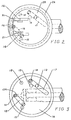
- the leaf spring 12 has a forked end 12A for engaging under the head 11B of the needle member 11 to urge the head 11B continually into contact with the diaphragm 2 is shown in Figure 3 and in dashed lines in Figure 2.
- a gas outlet 13 (shown in Figure 3 and in dashed lines in Figure 2) connects the first chamber 3 to an appropriate means, for example a face mask, for delivering breathing gas to a user.
- the second chamber 4 is connected to the ambient atmosphere by a vent 14 in the housing cover 1B and the first chamber 3 further includes two pivot members 15 constituting a pivot means engaging the diaphragm 2 on a pivot axis defined by the line between the tops of the two pivot members 15.
- the pivot axis lies between the centre of gravity of the diaphragm 2 and the gas inlet constituted by the gas inlet channel 5 and the orifice 7.
- a pair of v-shaped leaf springs 16 is mounted to the housing cover 1B within the second chamber 4, so that the apex of each v-shaped leaf spring 16 engages the opposite side of the diaphragm 2 to the pivot members 15 along a line which is vertically above the pivot axis.
- the leaf springs 16 therefore urge the diaphragm 2 to stay on the pivot means while giving the diaphragm 2 a negligible moment to pivot in either direction. Effectively the leaf springs 16 engage the diaphragm 2 along the line of the pivot axis.
- the leaf springs 16 apply sufficient loading to ensure that the diaphragm 2 remains in contact with the pivot means 15 under the highest anticipated pressure above atmospheric that may be experienced in the first chamber 3, which is typically the pressure generated on exhalation by a user, for example a patient.
- a leaf spring 17 is mounted to the housing body 1A by a screw 18 and extends into the first chamber 3 into contact with the diaphragm 2 at a position near to the edge of the diaphragm 2 on the opposite side of the pivot members 15 to the gas inlet channel 5.
- Leaf spring 17 urges the diaphragm 2 to pivot about the pivot members 15 to urge the needle member downwardly in the gas inlet channel 5 in a direction to cause the needle 11A to close the orifice 7.
- Leaf spring 17 is an adjustable leaf spring, a screw 19 in a tapped hole 20 being provided to bend the leaf spring 17 upwards and exert a greater or lesser force on the diaphragm 2, depending on the position of the screw 19.
- Additional leaf spring means is provided in the second chamber 4 in the form of a pair of additional leaf springs 21 which are mounted to the housing cover 1B in positions adjacent to the v-shaped leaf springs 16 so that the ends of the additional leaf springs 21 contact the diaphragm 2 at a small distance to the right of the pivot axis and the contact between the v-shaped leaf springs 16 and the diaphragm 2.
- the additional leaf springs 21 urge the diaphragm 2 to pivot clockwise to open the gas inlet by allowing the needle 11 to move out of sealing engagement with the orifice 7 in the gas inlet channel 5.
- the v-shaped leaf springs 16 and the additional leaf springs 21 are combined in a single part comprising a common base member 22 with twin leaf springs 16 and 21 extending from the common base member 22, as shown in Figure 2.
- Each leaf spring 16 and each leaf spring 21 is therefore made up of two leaf springs acting in unison.
- the adjustable leaf spring 17 and the additional leaf springs 21 are provided to balance the loads on the diaphragm 2 to achieve any required opening pressure, at which the needle 11A of needle member 11 will move out of sealing engagement in the orifice 7 and allow gas to pass through the gas inlet channel 5 to the first chamber 3.
- the gas inlet closes when the load exerted by the leaf spring 17 is sufficient to overcome the combined moments resulting from the load exerted on the diaphragm by the needle member 11 as a result of the supply pressure and the action of leaf spring 12 (if provided), and by leaf spring 21.
- the diaphragm will stay in its closed position until the pressure in the first chamber 3 falls to a level at which the clockwise moment on the diaphragm 2 due to the pressure difference across the diaphragm 2 is sufficient to overcome the resultant moment of the above mentioned forces on the diaphragm 2.
- This pressure in the first chamber is the opening pressure of the valve.
- the design and arrangement of the leaf springs 12, 16, 17, and 21 can be adjusted to give a wide range of opening pressures above or below atmospheric pressure.
- the test or over-ride mechanism comprises essentially an over-ride leaf spring 24 which is mounted in the housing cover 1B by a bolt 25 near one end of the over-ride leaf spring 24 so that the override leaf spring 24 is substantially parallel to the diaphragm 2.
- a cylindrical button 26 is a sliding fit in an opening through the housing cover 1B, the housing cover 1B being recessed at 27 so that the button 26 may protrude beyond the surface of the housing cover 1B which surrounds the opening without extending through the outer plane of the housing cover 1B with consequential risk of accidental operation.
- the leaf spring 24 is shaped to have a narrower flexible portion 28 remote from the bolt 25 for easy flexing of the over-ride leaf spring 24 under the action of button 26.
- the over-ride leaf spring 24 is caused to bend so that the end 29 of the over-ride leaf spring 24 remote from the bolt 25 comes into contact with the diaphragm 2 and moves the diaphragm 2 against the action of the adjustable leaf spring 17 to permit movement of needle member 11 to open the orifice 7 of the gas inlet and permit gas to flow through the valve either as a simple test or for use in resuscitation or a similar application where breathing gas is to be forced into the lungs of a patient.
- the load applied to the diaphragm by the over-ride leaf spring 24 may be predetermined by appropriate selection of the thickness, length and width of the over-ride leaf spring 24.
- the pressure of breathing gas delivered by the valve under test or over-ride conditions will be affected by the characteristics of the over-ride leaf spring.
- a stiff over-ride leaf spring 24 will provide gas under higher pressure for a given movement of the button 26 than a more flexible over-ride leaf spring.
- a stiffer over-ride leaf spring is therefore used when a negative pressure demand valve is to be employed in, for example, artificial respiration, and gas is to be forced into the lungs of a patient.
- a more flexible over-ride leaf spring 24 is all that is required if the button 26 is to be used solely for test purposes.
- over-ride leaf spring 24 is flexible between the point of action of the button 26 on the over-ride leaf spring 24 and the point of contact 29 of the over-ride leaf spring 24 with the diaphragm 2, movement of the button 26 gives a progressive opening of the valve rather than a quick switch between off and on positions as would occur if a rigid member was used to act on the diaphragm 2.
- the flexibility in the over-ride leaf spring 24 affects the relationship between the movement of the button 26, the stiffness of the button 26 and the load exerted on the diaphragm 2.
- the flexibility of the narrower section 28 of the over-ride leaf spring 24 has the greater effect on the load exerted on the diaphragm 2, and the flexibility of the wider section of the over-ride leaf spring 24, through which the bolt 25 passes, has the greater effect on the stiffness of the button 26.
- test or over-ride mechanism incorporating an over-ride leaf spring and button as described above has application to other valves than the particular demand valve described and illustrated herein.
- the test or over-ride mechanism may be used with any valve employing a movable diaphragm to control flow through the valve.
- the present invention provides a valve for use in breathing apparatus comprising a housing, a diaphragm mounted within the housing and, together with the housing, defining a first chamber on one side of the diaphragm and a second chamber on the other side of the diaphragm, the second chamber being connected to atmosphere, a gas inlet to the first chamber, a gas outlet from the first chamber, the gas inlet to the first chamber being closed when there is a predetermined pressure in the first chamber and the diaphragm being mounted for movement in response to a decrease of pressure below the predetermined pressure in the first chamber to open the gas inlet to admit gas from a source thereof to the first chamber, an over-ride leaf spring means secured in the second chamber adjacent a wall of the housing defining the second chamber, and a button slidable in an aperture in said wall to contact the over-ride leaf spring and deflect the over-ride leaf spring to move the diaphragm to open the gas inlet to the first chamber in the absence of a pressure lower
- the valve according to this aspect of the present invention may be designed for use in artificial respiration, in which case a relatively stiff over-ride leaf spring is used, or for simple testing purposes, in which case a more flexible override leaf spring may be employed.
- an intermediate member to close the gas inlet as hereinbefore described is another feature which has application in other valves than the particular demand valve described and claimed herein.
- an intermediate member may be used in a valve according to UK Patent No. 2 190 001.
- a valve for use in breathing apparatus comprising a housing, a diaphragm mounted within the housing, and, together with the housing, defining first and second chambers on opposite sides of the diaphragm, a gas inlet to the first chamber which comprises a gas inlet channel extending within the housing between the first chamber and a gas supply channel, an orifice in the gas inlet channel permitting a restricted flow of gas from the gas supply channel to the gas inlet channel, and an intermediate member located in the gas inlet channel between the orifice and the first chamber, the intermediate member comprising a main body adapted for sliding movement within the gas inlet channel but permitting passage of gas along the gas inlet channel past the main body, a sealing device projecting from the main body adjacent to the orifice and movable into and out of sealing engagement with the orifice, and a head extending from the main body into the first chamber, a gas outlet from the first chamber, vent means in the housing connecting the second chamber to a reference pressure, and pivot means
- the intermediate member is preferably a needle member as herein disclosed having a needle as the sealing device which is movable into and out of sealing engagement with the orifice.
- a needle as the sealing device which is movable into and out of sealing engagement with the orifice.
- other sealing devices may be employed, for example a ceramic ball. If the orifice is formed in a raised seat, for example a frustum, the sealing device may be a suitable flat surface.
- FIG. 1 of the accompanying drawings shows the valve of the present invention used as part of a pilot-operated demand valve in association with an inhale valve which is the subject of our co-pending European Patent Application No. 0582419.
Landscapes
- Health & Medical Sciences (AREA)
- Pulmonology (AREA)
- General Health & Medical Sciences (AREA)
- Business, Economics & Management (AREA)
- Emergency Management (AREA)
- Respiratory Apparatuses And Protective Means (AREA)
- Safety Valves (AREA)
Claims (13)
- Soupape destinée à être utilisée dans un appareil respiratoire, comprenant un boîtier (1), un diaphragme (2) monté dans le boîtier et définissant avec le boîtier une première chambre (3) située d'un côté du diaphragme et une deuxième chambre (4) située de l'autre côté du diaphragme, une entrée de gaz (5) donnant sur la première chambre, une sortie de gaz (13) partant de la première chambre, des moyens d'évent (14), prévus dans le boîtier et reliant la deuxième chambre à l'atmosphère amiante, des moyens formant pivot (15) logés dans la première chambre pour attaquer le diaphragme sur un axe de pivotement situé entre le centre de gravité du diaphragme et l'entrée de gaz, ladite soupape étant caractérisée par des premiers moyens élastiques (16) fixés au boîtier à l'intérieur de la deuxième chambre (4), qui se prolongent jusqu'a entrer en contact avec la face du diaphragme située à l'opposé des moyens formant pivot (15) et qui appliquent au diaphragme une force dirigée vers l'axe de pivotement pour maintenir le diaphragme (2) en appui contre les moyens formant pivot, et d'autres moyens élastiques (17) fixés au boîtier (1) et qui se prolongent dans la première chambre jusqu'à entrer en contact avec le diaphragme en un point situé sur le côté des moyens formant pivot qui est à l'opposé de l'entrée de gaz (5) et tendent à faire pivoter le diaphragme de telle manière que la partie du diaphragme située sur le même côté des moyens formant pivot que l'entrée de gaz soit entraîné en mouvement dans le sens approprié pour fermer l'entrée de gaz (5), de sorte que l'entrée de gaz (5) est fermée par le diaphragme aux pressions inférieures à la pression atmosphérique.
- Soupape selon la revendication 1, comprenant en outre des moyens de réglage (19, 20) servant à régler les autres moyens élastiques (17) pour faire varier le moment autour du pivot qui est exercé par les autres moyens élastiques.
- Soupape selon la revendication 1 ou 2, dans laquelle les premiers moyens élastiques sont des premiers moyens du type ressort lame (16).
- Soupape selon une quelconque des revendications 1 à 3, dans laquelle les autres moyens élastiques sont d'autres moyens du type ressort lame (17).
- Soupape selon une quelconque des revendications 1 à 4, comprenant des moyens élastiques additionnels (21) fixés au boîtier à l'intérieur de la deuxième chambre (4) et qui se prolongent jusqu'à entrer en contact avec le diaphragme (2) en un point situé du côté des moyens formant pivot qui est à l'opposé de l'entrée de gaz (5).
- Soupape selon la revendication 5, dans laquelle les moyens élastiques additionnels comprennent des moyens additionnels du type ressort lame (21).
- Soupape selon la revendication 5 ou la revendication 6, dans laquelle les premiers moyens élastiques (16) et les moyens élastiques additionnels (21) sont combinés en une seule pièce qui comprend un élément de base commun et deux ressorts lames jumeau qui partent de cet élément, un ressort lame jumeau étant les premiers moyens élastiques et l'autre ressort lame jumeau étant les moyens élastiques additionnels.
- Soupape selon la revendication 1, dans laquelle lesdits premiers moyens élastiques comprennent des moyens du type ressort lame (16) en forme de V fixés au boîtier (1) à l'intérieur de la deuxième chambre (4) de manière que le sommet des moyens du type ressort lame (16) en forme de V entre en contact avec le diaphragme (2) en un point situé dans la deuxième chambre en face de l'axe formant pivot, pour tendre à mettre le diaphragme en appui contre le pivot dans toutes les conditions de fonctionnement tout en n'imprimant au diaphragme qu'un moment négligeable tendant à le faire pivoter autour du moyen pivot, et dans laquelle lesdits autres moyens élastiques comprennent des moyens du type ressort lame réglables (17) fixés au boîtier à l'intérieur de la première chambre (3) et qui se prolongent dans la première chambre jusqu'à entrer en contact avec le diaphragme en un point situé sur le côté des moyens formant pivot qui est à l'opposé de l'entrée de gaz, et tendent à faire pivoter le diaphragme de manière que la partie du diaphragme située du même côté des moyens formant pivot que l'entrée de gaz soit entraînée dans un sens approprié pour fermer l'entrée de gaz, et des moyens élastiques additionnels (21) du type ressort lame fixés au boîtier dans la deuxième chambre (4) et qui se prolongent dans la deuxième chambre jusqu'à entrer en contact avec le diaphragme en un point situé entre le point de contact du sommet des moyens du type ressort lame en forme de V avec le diaphragme et le point de contact des moyens du type ressort lame réglables (17) avec le diaphragme, les moyens du type ressort lame réglables ayant pour effet d'exercer un plus grand moment autour de l'axe de pivotement que les moyens additionnels du type ressort lame (21), de sorte que l'entrée de gaz (5) est fermee aux pressions inférieures à la pression atmosphérique.
- Soupape selon la revendication 8, dans laquelle l'entrée de gaz aboutissant à la première chambre comprend un canal d'entrée de gaz (5) s'étendant entre la première chambre et un canal (6) d'arrivée du gaz situé dans le boîtier (1), le canal d'entrée de gaz (5) comprend un orifice (7) qui relie le canal d'entrée de gaz au canal d'arrivée de gaz, et un élément à aiguille (11) alternatif est logé dans le canal d'entrée de gaz entre l'orifice et la première chambre (3), l'élément a' aiguille comprenant un corps principal adapté pour se déplacer le long du canal mais permettant au gaz de passer le long du canal d'entrée de gaz au droit du corps principal, une aiguille (11a) placée sur le corps principal à proximité de l'orifice et qui peut être mise en appui de fermeture étanche sur l'orifice et dégagée de cet appui, et une tête (11b) qui fait saillie sur le corps principal en s'engageant dans la première chambre jusqu'à entrer en contact avec le diaphragme (2), de sorte que le diaphragme amène l'élément à aiguille à mettre l'aiguille en appui de fermeture étanche sur l'orifice (7) lorsque les moments exercés sur le diaphragme par la pression régnant dans la première chambre et par les moyensdu type ressort lame réglables (17) excèdent les moments exercés sur le diaphragme par la pression régnant dans la deuxième chambre et par les moyens additionnels du type ressort lame (21).
- Soupape selon la revendication 9, dans laquelle il est encore prévu des moyens du type ressort lame de tête d'aiguille (12) qui sont fixés au boîtier dans la première chambre (3) et qui attaquent la tête (11b) de l'élément à aiguille (11) pour tendre continuellement à mettre la tête de l'élément à aiguille en contact avec le diaphragme (2).
- Soupape selon une quelconque des revendications 8 à 10, comprenant en outre un ressort lame de commande prioritaire (24) fixé dans la deuxième chambre (4), le ressort lame de commande prioritaire étant adjacent à une paroi du boîtier qui définit la deuxième chambre, ladite paroi présentant une ouverture et un bouton (26) qu'on peut faire coulisser dans ladite ouverture pour le mettre en contact avec le ressort lame de commande prioritaire (24) et faire fléchir le ressort lame de commande prioritaire pour repousser le diaphragme (2) à l'encontre de l'action des moyens du type ressort lame réglables (17) pour obtenir un écoulement à travers la soupape sans qu'un utilisateur ne cherche à aspirer du gaz de la soupape.
- Soupape selon une quelconque des revendications précédentes, qui est une soupape de demande.
- Soupape selon une quelconque des revendications 1 à 11, qui est une soupape pilote commandant une soupape principale.
Applications Claiming Priority (2)
| Application Number | Priority Date | Filing Date | Title |
|---|---|---|---|
| GB939301959A GB9301959D0 (en) | 1993-02-01 | 1993-02-01 | A valve for use in breathing apparatus |
| GB9301959 | 1993-02-01 |
Publications (2)
| Publication Number | Publication Date |
|---|---|
| EP0610054A1 EP0610054A1 (fr) | 1994-08-10 |
| EP0610054B1 true EP0610054B1 (fr) | 1997-11-05 |
Family
ID=10729663
Family Applications (1)
| Application Number | Title | Priority Date | Filing Date |
|---|---|---|---|
| EP94300714A Expired - Lifetime EP0610054B1 (fr) | 1993-02-01 | 1994-01-31 | Soupape pour appareil respiratoire |
Country Status (4)
| Country | Link |
|---|---|
| US (1) | US5464009A (fr) |
| EP (1) | EP0610054B1 (fr) |
| DE (1) | DE69406561T2 (fr) |
| GB (1) | GB9301959D0 (fr) |
Families Citing this family (14)
| Publication number | Priority date | Publication date | Assignee | Title |
|---|---|---|---|---|
| USD383406S (en) * | 1996-03-01 | 1997-09-09 | Air Liquide America Corporation | Instrument calibrating demand flow regulator |
| GB9619459D0 (en) * | 1996-09-18 | 1996-10-30 | Jackson Peter J | Breathing apparatus |
| AU6590798A (en) * | 1997-04-03 | 1998-10-22 | Scott Technologies, Inc. | Self contained breathing apparatus |
| US5881725A (en) * | 1997-08-19 | 1999-03-16 | Victor Equipment Company | Pneumatic oxygen conserver |
| NO311186B1 (no) * | 1999-12-13 | 2001-10-22 | Techwood As | Ventilanordning for styrt tilförsel av et trykkfluid |
| US6364161B1 (en) | 2000-09-27 | 2002-04-02 | Victor Equipment Company | Oxygen conserver |
| US7066175B2 (en) * | 2001-05-07 | 2006-06-27 | Emergent Respiratory Products, Inc. | Portable gas powered positive pressure breathing apparatus and method |
| US6484721B1 (en) | 2001-06-27 | 2002-11-26 | Chad Therapeutics, Inc. | Pneumatic oxygen conserving device |
| US6966316B2 (en) * | 2002-06-24 | 2005-11-22 | Survivair Respirators, Inc. | Clean gas purge for breathing gas regulator |
| GB0426676D0 (en) | 2004-12-04 | 2005-01-05 | Concept 2 Manufacture Design L | A regulator for medical use |
| DE102007012729B3 (de) * | 2007-03-16 | 2008-07-03 | Dräger Medical AG & Co. KG | Dosierventil für Atemgas |
| NZ586099A (en) | 2007-11-19 | 2012-05-25 | Carefusion 2200 Inc | Patient interface assembly comprising a jet pump including a venturi assembly defining an entrainment region, a throat region and an expansion region |
| WO2011136674A1 (fr) | 2010-04-19 | 2011-11-03 | ПУСТЫННИКОВ, Сергей Сергеевич | Appareil respiratoire |
| GB2639637A (en) | 2024-03-20 | 2025-10-01 | Bpr Medical Ltd | Therapeutic gas delivery system coupling |
Family Cites Families (23)
| Publication number | Priority date | Publication date | Assignee | Title |
|---|---|---|---|---|
| US2563228A (en) * | 1951-08-07 | Accelerating device fok gas pres | ||
| GB796336A (en) * | 1955-03-11 | 1958-06-11 | Blending Machine Company Ltd | Improvements relating to magnetic separators for fluent materials |
| US3285261A (en) * | 1962-12-21 | 1966-11-15 | Robertshaw Controls Co | Breathing demand regulator |
| US3272143A (en) * | 1963-05-20 | 1966-09-13 | Ohlsson & Rice Inc | Demand fuel regulator and priming pump |
| GB1106766A (en) * | 1965-05-13 | 1968-03-20 | British Oxygen Co Ltd | Fluid flow regulators |
| SE336528B (fr) * | 1970-03-12 | 1971-07-05 | Aga Ab | |
| DE2404062C3 (de) * | 1974-01-29 | 1978-04-20 | Draegerwerk Ag, 2400 Luebeck | Atemgaszuführungsregler, insbesondere für Höhenatemgeräte |
| US3974851A (en) * | 1974-01-31 | 1976-08-17 | Garretson Equipment Co., Inc. | Demand type governors |
| US4106510A (en) * | 1976-11-26 | 1978-08-15 | Hakim Company Limited | Servo valve |
| US4289126A (en) * | 1979-05-02 | 1981-09-15 | Wisconsin Alumni Research Foundation | Pressure regulator for breathing apparatus |
| US4266538A (en) * | 1979-05-08 | 1981-05-12 | General Diving Corporation | Pressure regulator |
| US4411285A (en) * | 1980-05-20 | 1983-10-25 | Submarine Products Limited | Demand valve |
| FR2511252A1 (fr) * | 1982-04-02 | 1983-02-18 | Fenzy Sa | Embout pour appareil respiratoire pour le raccordement du masque a une bouteille de gaz respiratoire |
| DE3245717C1 (de) * | 1982-12-10 | 1984-06-07 | Drägerwerk AG, 2400 Lübeck | Lungengesteuertes Ventil fuer den UEberdruckbetrieb im Maskeninnenraum |
| GB2190001B (en) * | 1986-05-07 | 1990-08-08 | Peter Joseph Jackson | Pressure regulator |
| AU593903B2 (en) * | 1986-05-07 | 1990-02-22 | Peter Joseph Jackson | Pressure regulator |
| GB8621516D0 (en) * | 1986-09-06 | 1986-10-15 | Jackson P J | Pilot operated valves |
| GB2234368B (en) * | 1986-09-06 | 1991-07-31 | Peter Joseph Jackson | Pilot operated valves |
| GB2239328B (en) * | 1986-09-06 | 1991-09-25 | Peter Joseph Jackson | Pilot operated valves |
| GB2195900B (en) * | 1986-09-06 | 1991-07-24 | Peter Joseph Jackson | Pilot operated valves |
| DE3840058A1 (de) * | 1988-11-28 | 1990-05-31 | Auergesellschaft Gmbh | Lungengesteuertes ventil |
| US5245997A (en) * | 1991-12-05 | 1993-09-21 | Respirator Research, Inc. | Valve cartridge assembly for a pressure regulator of supplied air breathing apparatus |
| US5357950A (en) * | 1993-03-02 | 1994-10-25 | Comasec International S.A. | Breath actuated positive pressure demand regulator with override |
-
1993
- 1993-02-01 GB GB939301959A patent/GB9301959D0/en active Pending
-
1994
- 1994-01-31 EP EP94300714A patent/EP0610054B1/fr not_active Expired - Lifetime
- 1994-01-31 DE DE69406561T patent/DE69406561T2/de not_active Expired - Lifetime
- 1994-02-01 US US08/189,609 patent/US5464009A/en not_active Expired - Lifetime
Also Published As
| Publication number | Publication date |
|---|---|
| US5464009A (en) | 1995-11-07 |
| EP0610054A1 (fr) | 1994-08-10 |
| DE69406561D1 (de) | 1997-12-11 |
| GB9301959D0 (en) | 1993-03-17 |
| DE69406561T2 (de) | 1998-03-05 |
Similar Documents
| Publication | Publication Date | Title |
|---|---|---|
| EP0610054B1 (fr) | Soupape pour appareil respiratoire | |
| US5042473A (en) | Demand valve for a respirator | |
| US6364161B1 (en) | Oxygen conserver | |
| US5937855A (en) | Flow regulating valve in a breathing gas delivery system | |
| US5685296A (en) | Flow regulating valve and method | |
| US7775208B2 (en) | Device for supplying breathing gas, particularly for mouthpiece of a diver | |
| US4367767A (en) | Servo-controlled gas pressure relief valve | |
| JP5735049B2 (ja) | ガスレギュレータの調節可能な弁体機構 | |
| WO1994000195A1 (fr) | Commande du volume d'air d'un regulateur de deuxieme etage pour scaphandre autonome | |
| EP0726862B1 (fr) | Systeme de soupape et regulateur de respiration le comprenant | |
| EP0510040B1 (fr) | Appareil de respiration | |
| US4334532A (en) | Valves and breathing apparatus incorporating such valves | |
| GB2274595A (en) | Breathing apparatus with demand valves | |
| US6116576A (en) | Membrane valve with structure for assuring a tight seal in the closed position | |
| US4667670A (en) | Gas flow control valves | |
| JPH078393Y2 (ja) | 圧力調整装置 | |
| US4337766A (en) | Valves | |
| US6786231B2 (en) | Fluid flow regulator with restrictor pin | |
| EP0019488B1 (fr) | Soupape basculante et respirateur dans lequel elle est utilisée | |
| EP0078644A2 (fr) | Régulateur de refoulement de gaz respiratoir | |
| GB2087732A (en) | Valves | |
| CN224135184U (zh) | 音圈电机膜片比例阀及呼吸设备 | |
| AU2001286354A1 (en) | A vacuum regulator for maintaining a substantially constant vacuum in a vacuum system | |
| US20050056284A1 (en) | Electronic breathing system | |
| JPH0220876B2 (fr) |
Legal Events
| Date | Code | Title | Description |
|---|---|---|---|
| PUAI | Public reference made under article 153(3) epc to a published international application that has entered the european phase |
Free format text: ORIGINAL CODE: 0009012 |
|
| AK | Designated contracting states |
Kind code of ref document: A1 Designated state(s): DE ES FR GB IT |
|
| 17P | Request for examination filed |
Effective date: 19950110 |
|
| 17Q | First examination report despatched |
Effective date: 19960322 |
|
| GRAG | Despatch of communication of intention to grant |
Free format text: ORIGINAL CODE: EPIDOS AGRA |
|
| GRAH | Despatch of communication of intention to grant a patent |
Free format text: ORIGINAL CODE: EPIDOS IGRA |
|
| GRAH | Despatch of communication of intention to grant a patent |
Free format text: ORIGINAL CODE: EPIDOS IGRA |
|
| GRAA | (expected) grant |
Free format text: ORIGINAL CODE: 0009210 |
|
| AK | Designated contracting states |
Kind code of ref document: B1 Designated state(s): DE ES FR GB IT |
|
| PG25 | Lapsed in a contracting state [announced via postgrant information from national office to epo] |
Ref country code: IT Free format text: LAPSE BECAUSE OF FAILURE TO SUBMIT A TRANSLATION OF THE DESCRIPTION OR TO PAY THE FEE WITHIN THE PRESCRIBED TIME-LIMIT;WARNING: LAPSES OF ITALIAN PATENTS WITH EFFECTIVE DATE BEFORE 2007 MAY HAVE OCCURRED AT ANY TIME BEFORE 2007. THE CORRECT EFFECTIVE DATE MAY BE DIFFERENT FROM THE ONE RECORDED. Effective date: 19971105 Ref country code: ES Free format text: THE PATENT HAS BEEN ANNULLED BY A DECISION OF A NATIONAL AUTHORITY Effective date: 19971105 |
|
| REF | Corresponds to: |
Ref document number: 69406561 Country of ref document: DE Date of ref document: 19971211 |
|
| ET | Fr: translation filed | ||
| PLBE | No opposition filed within time limit |
Free format text: ORIGINAL CODE: 0009261 |
|
| STAA | Information on the status of an ep patent application or granted ep patent |
Free format text: STATUS: NO OPPOSITION FILED WITHIN TIME LIMIT |
|
| 26N | No opposition filed | ||
| REG | Reference to a national code |
Ref country code: GB Ref legal event code: 732E |
|
| REG | Reference to a national code |
Ref country code: FR Ref legal event code: TP |
|
| REG | Reference to a national code |
Ref country code: GB Ref legal event code: IF02 |
|
| PGFP | Annual fee paid to national office [announced via postgrant information from national office to epo] |
Ref country code: GB Payment date: 20080107 Year of fee payment: 15 |
|
| GBPC | Gb: european patent ceased through non-payment of renewal fee |
Effective date: 20090131 |
|
| PG25 | Lapsed in a contracting state [announced via postgrant information from national office to epo] |
Ref country code: GB Free format text: LAPSE BECAUSE OF NON-PAYMENT OF DUE FEES Effective date: 20090131 |
|
| PGFP | Annual fee paid to national office [announced via postgrant information from national office to epo] |
Ref country code: FR Payment date: 20130124 Year of fee payment: 20 Ref country code: DE Payment date: 20130103 Year of fee payment: 20 |
|
| REG | Reference to a national code |
Ref country code: DE Ref legal event code: R071 Ref document number: 69406561 Country of ref document: DE |
|
| PG25 | Lapsed in a contracting state [announced via postgrant information from national office to epo] |
Ref country code: DE Free format text: LAPSE BECAUSE OF EXPIRATION OF PROTECTION Effective date: 20140201 |