EP0610085B1 - Staurollenbahn mit bewegbarem Antriebsrad - Google Patents
Staurollenbahn mit bewegbarem Antriebsrad Download PDFInfo
- Publication number
- EP0610085B1 EP0610085B1 EP94300827A EP94300827A EP0610085B1 EP 0610085 B1 EP0610085 B1 EP 0610085B1 EP 94300827 A EP94300827 A EP 94300827A EP 94300827 A EP94300827 A EP 94300827A EP 0610085 B1 EP0610085 B1 EP 0610085B1
- Authority
- EP
- European Patent Office
- Prior art keywords
- drive
- drive wheel
- conveyor
- load
- driving
- Prior art date
- Legal status (The legal status is an assumption and is not a legal conclusion. Google has not performed a legal analysis and makes no representation as to the accuracy of the status listed.)
- Expired - Lifetime
Links
- 238000009825 accumulation Methods 0.000 title description 8
- 238000012423 maintenance Methods 0.000 description 6
- 230000007246 mechanism Effects 0.000 description 5
- 238000009434 installation Methods 0.000 description 2
- 230000002441 reversible effect Effects 0.000 description 2
- 230000003466 anti-cipated effect Effects 0.000 description 1
- 210000005069 ears Anatomy 0.000 description 1
- 238000007373 indentation Methods 0.000 description 1
- 238000004519 manufacturing process Methods 0.000 description 1
- 230000013011 mating Effects 0.000 description 1
- 230000032258 transport Effects 0.000 description 1
Images


Classifications
-
- B—PERFORMING OPERATIONS; TRANSPORTING
- B65—CONVEYING; PACKING; STORING; HANDLING THIN OR FILAMENTARY MATERIAL
- B65G—TRANSPORT OR STORAGE DEVICES, e.g. CONVEYORS FOR LOADING OR TIPPING, SHOP CONVEYOR SYSTEMS OR PNEUMATIC TUBE CONVEYORS
- B65G47/00—Article or material-handling devices associated with conveyors; Methods employing such devices
- B65G47/22—Devices influencing the relative position or the attitude of articles during transit by conveyors
- B65G47/26—Devices influencing the relative position or the attitude of articles during transit by conveyors arranging the articles, e.g. varying spacing between individual articles
- B65G47/261—Accumulating articles
- B65G47/263—Accumulating articles the conveyor drive is taken from a longitudinally extending shaft
Definitions
- the present invention relates to conveyors driven by a drive shaft extending along the conveyor.
- the primary type of driveshaft-driven conveyor used in the industry uses O-rings, which wrap around spools mounted on the drive shaft and around the conveyor rollers in order to drive the rollers as the drive shaft rotates.
- This type of conveyor has a speed limitation, because the O-rings may begin to slip at high speeds. It also is difficult to replace the O-rings when they break. It is also very difficult to stop portions of the O-ring driven conveyor for accumulation. Such an arrangement is shown in GB 2018213.
- Some conveyors which use a drive shaft and drive by a means other than O-rings. For example, it is known to put a gear on the driveshaft and a gear on the conveyor roller and have a direct drive from the driveshaft to the roller. This arrangement cannot be put into the accumulation mode, because, whenever the driveshaft is rotating, all the conveyor rollers are rotating.
- WO-A-92 04261 discloses a roller conveyor having a line drive shaft and a driven wheel which is connected to the drive shaft through a drive arrangement consisting of a drive wheel having a conical drive surface which is pressed into frictional engagement with a conical surface of an intermediate wheel having an axis normal to the axis of the drive shaft to transmit the drive to the drive wheel.
- This arrangement has proved to have disadvantages caused by low durability and excessive temperature build-up load capacity, which limits its speed and load carrying capacity.
- the present invention seeks to overcome these problems by providing a system having higher speed and load capabilities.
- Chain-driven roller conveyors are known, but they also have speed limitations, can be very noisy, and require substantial maintenance. Chain-driven conveyors are not readily reversible in direction, because a chain must always be pulled, not pushed.
- a conveyor comprising a conveyor frame, a drive shaft extending along said conveyor , at least one drive wheel supported by a mounting frame for driving a load along the conveyor, characterised in that the drive wheel is in direct permanent driving engagement with the drive shaft, and said drive wheel is pivotable about the axis of the drive shaft between a first, load driving, position and a second, load non-driving, position.
- the conveyor has a plurality of rollers rotatably mounted on said conveyor frame and forming a load supporting surface, said rollers each having an axis of rotation, characterised in that in said first position the drive wheel is in driving contact with at least one of the rollers and a second position in which the drive wheel is out of driving contact with said roller so that when said drive wheel is in said driving contact power is transmitted from said drive shaft through said drive wheel to said at least one roller, the axis of rotation of said drive wheel being substantially parallel to the axis of rotation of said at least one roller.
- the preferred embodiment of the present invention provides a conveyor with all the advantages of a driveshaft-driven conveyor, such as quiet operation, plus it can readily be put into an accumulation mode, in which portions of the conveyor can be stopped and started for accumulating products on the conveyor, and it has far fewer maintenance problems than standard O-ring, lineshaft conveyors and far fewer maintenance problems than chain-driven conveyors.
- the embodiment provides a much higher conveying speed than other accumulating conveyors, with a maximum speed of about 2.5 m/s (500 feet per minute), as compared with 1.3 m/s (250 feet per minute) for other known accumulating conveyors.
- the embodiment provides a simple, inexpensive conveyor design, which is easy to assemble and to maintain.
- the embodiment provides a conveyor which is reversible in two ways. It can be driven forward and backward simply by reversing the direction of rotation of the driveshaft. It also can be installed on the left or right side of the conveyor without changing any of the components.
- the embodiment provides a positive drive and eliminates the problems of replacing O-rings and the noise and maintenance problems of chain drives.
- the embodiment provides an arrangement in which the drive shaft and drive mechanism can be assembled onto one siderail and can be stocked in that manner to be used as standard, off-the-shelf stock for any width of conveyor. This stocked length of siderail and drive can then be combined with a second standard siderail and with cross-members of any width to make any width of conveyor. This greatly simplifies assembly and stocking requirements from other known conveyors.
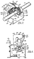
- the driveshaft 10 extends along the length of the conveyor frame 12.
- the driveshaft 10 is driven by a motor (not shown), and the direction of rotation of the driveshaft can be reversed simply by changing the side of the motor to which the negative electrical lead is attached, which will control the direction in which the conveyor transports articles.
- Conveyor rollers 14 are mounted on the conveyor frame 12. Each roller 14 has hexagonally-shaped shaft ends 16 which mount into hexagonally-shaped holes 18 on the left and right siderails 19, 21 of the conveyor frame 12, and the body of the roller 14 is freely rotatable relative to the shaft ends.
- Each drive gear support box 26 houses a drive gear 20, which is mounted on the driveshaft 10.
- a drive gear 20 which is mounted on the driveshaft 10.
- three of the support boxes 26 are shown. It is anticipated that there will be one drive gear 20 for every 76.2 cm (30 inches) of conveyor length.
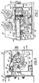
- the drive gear 20 and the rest of the drive mechanism are shown in more detail in Figures 3-10.
- each drive gear 20 On the front side of each drive gear 20 are radially-extending, backwardly-tapered teeth 22, and, molded to the inside of each drive gear 20 is a non-cylindrical core 24 (shown in Figure 5), which mates with the non-cylindrical outside surface of the pinion adapter 23 and which provides a good wear surface on the back side of the drive gear 20 for contacting the housing thrust washer 68.
- the pinion adapter 23 is fixed to the drive shaft 10 by means of set screws (not shown).
- the drive gear 20 can float axially relative to the driveshaft 10 by sliding axially along the pinion adapter 23 but that the drive gear 20 is driven whenever the driveshaft is driven.
- the driveshaft 10 drives the drive gear 20 by driving the pinion adapter 23, which is fixed to the drive shaft 10, and which mates with the non-cylindrical inner surface of the drive gear 20, thereby driving the drive gear 20.
- the support bracket or box 26 has an open top and upwardly-opening U-shaped cut-outs 28 in its front and back faces to permit the driveshaft 10 to extend through the support box 26 without contacting the support box 26.
- the drive gear 20 When the drive gear 20 is mounted over the driveshaft 10 and the support box 26 is mounted on the siderail, the drive gear 20 lies inside its respective support box 26, as can be seen in Figures 7 and 10.
- housing supports 30 are located at each of the U-shaped cut-outs 28 of the box 26.
- the housing supports 30 have ears 32 with holes 34 for fastening the housing supports 30 to the support box 26 by means of bolts 35 (the bolts 35 are shown best in Figure 10).
- Each housing support 30 also has a projection 36 on one side, which is shaped as a portion of a cylinder, covering approximately ⁇ radians (180 degrees), which projects through its respective U-shaped cut-out in the support box 26 when the housing support 30 is mounted on the box 26.
- the inside diameter of the projection 36 is larger than the diameter of the driveshaft 10, so the driveshaft 10 passes through the projections 36 of the housing supports 30 with a clearance fit.
- Each housing support 30 also defines an upwardly-opening U-shaped cut-out 37, which permits the driveshaft 10 to be dropped down into the box 26 from the top and to extend through the housing supports 30 with a clearance fit.
- a housing 38 Inside the support bracket or box 26 is mounted a housing 38, which is pivotably supported by the housing supports 30 of the box 26.
- the housing 38 has an open side 40, and the forward and rear faces 42, 44 of the housing 38 have horizontally-oriented U-shaped cut-outs 46, which open into the open side 40. These U-shaped cut-outs 46 are also large enough that the driveshaft 10 passes through them with a clearance fit.
- each of the U-shaped cut-outs 46 of the housing 38 is a pair of outwardly-projecting partial cylinders 48, 50, with a gap 52 defined between the partial cylinders 48, 50 for receiving the respective projection 36 of the housing support 30.
- These outwardly-projecting partial cylinders 48, 50 are preferably molded as an integral part of the housing 38. As shown best in Figure 4, the inner partial cylinder 50 extends about 270 degrees, and the outer partial cylinder 48 extends about 90 degrees.
- Figure 4 shows how the housing 38 is mounted onto the support box 26. First the housing 38 is rotated ⁇ /2 radians (90 degrees), until the open side 40 faces downwardly as shown in Figure 4. Then, the housing 38 is shifted downward until the driveshaft 10 enters the U-shaped cut-outs 46 in the housing 38. Then, the housing is rotated ⁇ /2 radians (90 degrees) back to its normal position, with the cylindrical projection 36 of each of the housing supports 30 entering the space or gap 52 between the respective partial cylinders 48, 50 on the end of the housing 38. This locks the housing 38 in place so that it can shift axially a small distance inside the support box 26, moving with the drive gear 20, and it can rotate relative to the driveshaft 10, but it cannot move vertically or shift left or right relative to the driveshaft.
- the wall 54 of the housing 38 which lies opposite the open face 40 defines a central hole 56, which receives a mounting bolt 58.
- a bearing 60 On the mounting bolt 58 is mounted a bearing 60.
- a driven gear 62 is mounted on the bearing 60.
- On the forward face of the driven gear 62 are radially-extending, rearwardly-tapered teeth 66, which mesh with the teeth 22 of the drive gear 20. From the moment the housing 38 is mounted on the support box 26, the drive gear 20 and the driven gear 62 are meshed, and they remain meshed as long as the housing 38 is installed on the support box or bracket 26.
- a drive wheel or tire 64 is mounted on the back of the driven gear 62, with a non-cylindrical mating connection between the driven gear 62 and the drive tire 64.
- the back portion of the driven gear 62 has a plurality of ridges 65 in its outer surface, and the inner surface of the drive tire 64 has corresponding indentations 67, which mate with the ridges 65.
- a housing thrust washer 68 has projecting feet 69, which snap through holes 47 on the inside of the housing 38 at the U-shaped cut-out 46 on the back face 44 of the housing 38 as shown in Figure 6.
- the thrust washer 68 could be snapped into holes 47 in the front face 42 of the housing 38 instead, if the drive gear 20 were to be mounted in the opposite direction.
- the thrust washer 68 provides a wear surface against which the rear of the core 24 of the drive gear 20 can push.
- the top surface 70 of the housing 38 defines openings 72 which permit the drive tire 64 to project through the top surface 70 in order to contact and drive two adjacent rollers 14.
- Figure 2 shows the drive tire 64 in broken lines as it drives two adjacent rollers 14.
- Figure 7 shows the drive tire 64 projecting through the cut-outs 72 in the housing 38 to drive the two adjacent rollers 14.
- An air-operated diaphragm 74 snaps onto a flat support bracket 76, which mounts to the box 26 by means of legs 77 that extend through slots 79 in the box 26 (shown best in Figure 5).
- the purpose of the diaphragm 74 is to move the drive wheel 64 up and down to engage and disengage it from driving the rollers 14.
- Figures 8 and 9 show the two positions the housing 38 takes, depending upon whether the diaphragm 74 is filled with air or not.
- air enters the diaphragm 74 it pushes the diaphragm 74 upwardly, and the diaphragm pushes the left bottom portion of the housing 38 upwardly, pivoting the housing clockwise, and moving the drive wheel 64 into driving contact with its respective rollers 14 as shown in Figure 8.
- the weight of the drive wheel support frame 38 causes it to pivot back down, moving the drive wheel 64 out of driving contact with the rollers 14 as shown in Figure 9.
- These drawings are exaggerated to show the pivoting motion.
- the drive tire 64 only has to move slightly (3mm or about 1/8 of an inch) to engage and disengage the rollers 14.
- each jump wheel 80 is mounted so as to contact two adjacent rollers 14, and the function of each jump wheel 80 is to transmit power from one roller to the other.
- Each jump wheel 80 is mounted in a spring-loaded bracket 82, which pushes the jump wheel 80 upward into contact with the two adjacent rollers 14 while giving the jump wheel enough play to find the center between the adjacent rollers 14.
- each drive tire 64 drives two adjacent rollers 14, those rollers 14 drive their respective jump wheels 80, which, in turn, drive other rollers 14, so that, for a normal conveyor, each drive tire 64 will end up driving five rollers 14 (i.e. three jump wheels 80 for every drive wheel 64).
- the number of rollers to be driven by each drive mechanism will depend upon the weight of the articles to be carried, with fewer jump wheels being used in a conveyor intended to convey very heavy articles.
- the diaphragm 74 is mounted on the diaphragm support bracket 76, which, in turn, is mounted on the main support bracket 26 by extending the legs 77 through the openings 79.
- the support bracket or support box 26 is bolted to the siderail 19 of the conveyor frame 12, and the housing supports 30 are bolted to the support bracket 26.
- the drive gears 20 (with their non-cylindrical cores 24) and the pinion adapters 23 are slipped over the drive shaft 10.
- the pinion adapters 23 are fixed to the driveshaft by means of set screws.
- the drive gears 20 are slipped over their respective pinion adapters 23 and can slide axially relative to the pinion adapters 23 while still being mounted on the pinion adapters. (When the driveshaft rotates, the pinion adapters rotate, causing the drive gears 20 to rotate.)
- the drive shaft is then dropped through the open top of the support bracket 26 into the U-shaped cut-outs 37 in the housing supports 36, with each drive gear 20 located inside its respective support bracket 26.
- the drive shaft 10 is mounted to the siderail 19 by means of bearings 17 which are bolted to every other support box 26. (The bearing 17 can be seen in Figure 1.)
- the drive shaft 10 is mounted so that there is clearance between the driveshaft 10 and the support box 26.
- the housing 38 is assembled and installed.
- the driven gears 62 and drive tires 64 are assembled together and mounted on their respective bearings 60 and in their respective housings 38 by means of bolts 58.
- the housings 38 are then rotated ⁇ /2 radians (90 degrees), are dropped down over the drive shaft 10, meshing the driven gear 62 with the drive gear 20, and the housings 38 are then rotated back ⁇ /2 radians (90 degrees) so that they are supported on the projections 36 of the housing supports 30.
- Each housing 38 can now pivot about the axis of the driveshaft 10 by pivoting on the projections 36 on the housing supports 30, which are coaxial with the driveshaft.
- the drive wheel frame (or housing) 38 rests on the diaphragm 74 at the bottom of the support box 26. Again, there is clearance between the driveshaft 10 and the housings 38.
- the axis of the drive wheel 64 is substantially parallel to the axes of the conveyor rollers 14 and substantially perpendicular to the axis of the driveshaft 10.
- a 3 metre (ten-foot) section of siderail 19 there should be four evenly-spaced support boxes 26 with their respective housings and gears.
- the preassembled 3 metre (ten-foot) section of siderail 19, driveshaft 10, support box 26 and housing 38 may be stored in a warehouse as a stock item.
- the drive mechanism is thus completely assembled in the section of left siderail 19.
- the jump wheels 80 are mounted on the right siderail 21
- a cross-member 29 is bolted between the left and right siderails 19, 21, defining the width of the conveyor
- the rollers 14 are mounted across the conveyor frame 12 by retracting one of the shaft ends 16 of each roller and placing the shaft ends 16 into the hexagonal holes 18 in the siderails 19, 21.
- Sections of the conveyor frame 12 are then bolted together, and sections of driveshaft 10 are connected together with known connectors (not shown).
- the drive motor (not shown) is attached to the driveshaft, and the conveyor is ready for operation.
- the air hoses, valves, and logic for controlling the diaphragms 74 are not shown, but they are standard, as used in known accumulation conveyors.
- the drive motor (not shown) Whenever the drive motor (not shown) is operating, it causes the driveshaft 10 to rotate, which causes all the drive gears 20 mounted on the driveshaft 10 to rotate.
- the driven gears 62 are constantly meshed with the drive gears 20, which eliminates any problem with meshing and unmeshing gears, and which means that, whenever the driveshaft 10 rotates, the driven gears 62 rotate.
- the driven gears 62 Because of the connection between the driven gears 62 and their respective drive wheels 64, the driven gears 62 cause the drive wheels 64 to rotate. Thus, whenever the driveshaft 10 rotates, the drive wheels 64 rotate.
- the force between the drive gear 20 and the driven gear 62 causes the driven gear to be pushed backward, to be stopped by the back surface of the core 24 of the drive gear 20 pushing against the housing thrust washer 68 mounted on the rear face 44 of the housing 38.
- the ability of the drive gear 20 to float axially permits the housing 38 to float with the drive gear 20, so that the drive wheel 64 can seek the center between the two rollers 14 it is driving. This ability to seek the center provides latitude in the manufacturing tolerances of the conveyor. It is also possible to fix the drive gear 20 to the driveshaft 10 so that it does not float axially along the driveshaft, by tightening a set screw in the drive gear 20 (not shown), if desired.
- the drive wheel mounting frame 38 rests on the diaphragm 74, and the drive wheel 64 lies under two adjacent rollers 14.
- the diaphragm 74 When the diaphragm 74 is inflated, it pivots the drive wheel support frame 38 upwardly, so that the drive wheel 64 contacts and drives its two rollers 14.
- the drive wheel 64 When air pressure is exhausted from the diaphragm 74, the drive wheel 64 pivots downward, out of driving contact with the conveyor rollers 14, so the rollers 14 stop rotating and can be used to accumulate product.
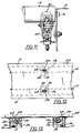
- An alternate embodiment of the conveyor could be made by installing springs in the place of the diaphragms 74.
- This type of installation is shown in Figure 14.
- the spring 101 keeps the drive wheel housing 38 in the raised, driving position at all times. This installation could be made if the customer does not want to use the conveyor for accumulation at the outset but wants the option of converting to accumulation at a later time.
- the springs 101 are installed on the diaphragm support bracket 76 in order to keep the drive wheel 64 in contact with its rollers 14 at all times.
- the rollers 14 rotate whenever the driveshaft 10 rotates, and sections of the conveyor cannot be stopped without stopping the entire conveyor.
- this continues to be a simple, easily-maintained conveyor, and it can be converted to an accumulation conveyor at any time, simply by adding the diaphragms 74, an air compressor, and air hoses running to the diaphragms 74.
- a second alternative embodiment shown in Figures 12 and 13, eliminates the conveyor rollers entirely and uses the drive wheels 64 to convey the products.
- two parallel driveshafts 10 are used.
- Left and right drive wheels 64 are located opposite to each other and can be used to drive pallets.
- the drive wheels 64 pivot upwardly through holes 210 in a table 212 in order to contact the pallets directly and move the pallets along the conveyor path defined by the table 212.
- the support boxes 26, housing supports 30, housings 38, and drive gear and driven gear arrangement are identical in this embodiment to the first embodiment. The basic difference is that there are no rollers 14, so the drive tires 64 contact the product directly.
Landscapes
- Engineering & Computer Science (AREA)
- Mechanical Engineering (AREA)
- Rollers For Roller Conveyors For Transfer (AREA)
- Intermediate Stations On Conveyors (AREA)
Claims (8)
- Fördereinrichtung, mit einem Fördereinrichtungs-Rahmen (12), einer Antriebswelle (10), die sich entlang der Fördereinrichtung erstreckt, zumindest einem Antriebsrad (64), das durch einen Halterahmen (38) abstützend gehalten ist, um eine Last entlang der Fördereinrichtung zu fördern, dadurch gekennzeichnet, daß
sich das Antriebsrad (64) in einem direkten, permanenten antreibenden Eingriff mit der Antriebswelle (10) befindet und das Antriebsrad (64) uni die Achse der Antriebswelle (10) zwischen einer ersten lastantreibenden Stellung und einer zweiten nicht-lastantreibenden Stellung schwenkbar ist. - Fördereinrichtung nach Anspruch 1, mit einer Anzahl von Rollen (14), die drehbar an dem Fördereinrichtungs-Rahmen (12) montiert und eine Lastabstützungsfläche bilden, wobei die Rollen jeweils eine Drehachse haben, dadurch gekennzeichnet, daß
sich das Antriebsrad (64) in der ersten Stellung in antreibendem Kontakt mit zumindest einer der Rollen (14) befindet und sich das Antriebsrad (64) in einer zweiten Stellung nicht in antreibendem Kontakt mit der Rolle befindet, so daß, wenn sich das Antriebsrad (64) in antreibendem Kontakt befindet, Kraft von der Antriebswelle (10) über das Antriebsrad (64) auf die zumindest eine Rolle (14) übertragen wird, wobei die Drehachse des Antriebsrades (64) im wesentlichen parallel zu der Drehachse der zumindest einen Rolle (14) verläuft. - Fördereinrichtung nach Anspruch 1, dadurch gekennzeichnet, daß die Last auf einer Lastabstützungsfläche abstützend gehalten ist, sich das Antriebsrad (64) in der ersten Stellung in direktem, antreibenden Kontakt mit der Last befindet und die Last deutlich von der Abstützungsfläche abhebt, um dadurch die Last entlang der Fördereinrichtung zu fördern.
- Fördereinrichtung nach einem der Ansprüche 1 bis 3, dadurch gekennzeichnet, daß die Einrichtung zum Antreiben des Antriebsrades (64) durch die Antriebswelle (10) ein antreibendes Zahnrad (20), das an der Antriebswelle (10) montiert ist, und ein angetriebenes Zahnrad (62) aufweist, das an dem Antriebsrad-Halterahmen (38) montiert ist und mit dem antreibenden Zahnrad (20) kämmt, so daß, wenn das Antriebsrad (64) durch den Antriebsrad-Halterahmen (38) aus einem antreibenden Kontakt mit der Last oder der zumindest einen Rolle (14) herausbewegt wird, das antreibende Zahnrad (20) und das angetriebene Zahnrad (62) fortwährend in Eingriff bleiben.
- Fördereinrichtung nach Anspruch 4, dadurch gekennzeichnet, daß das angetriebene Zahnrad (62) und das Antriebsrad (64) um die gleiche Achse drehbar montiert sind, so daß eine Drehung des angetriebenen Zahnrades (62) eine Drehung des Antriebsrades (64) bewirkt.
- Fördereinrichtung nach einem der Ansprüche 1 bis 5, dadurch gekennzeichnet, daß der Antriebsrad-Halterahmen (38) schwenkbar an einem Träger (26) gehalten ist, der an dem Fördereinrichtungs-Rahmen (12) montiert ist.
- Fördereinrichtung nach einem der Ansprüche 1 bis 6, dadurch gekennzeichnet, daß das Antriebsrad (64) um eine Achse drehbar ist, die im wesentlichen senkrecht zu der Achse der Antriebswelle (10) verläuft, und der Antriebsrad-Halterahmen (38) relativ zu dem Fördereinrichtungs-Rahmen (12) bewegbar ist, so daß, wenn der Halterahmen (38) nach oben bewegt wird, sich das Antriebsrad (64) in antreibendem Kontakt mit der Last oder der zumindest einen Rolle (14) befindet, und, wenn der Halterahmen (38) nach unten bewegt wird, sich das Antriebsrad (64) nicht in antreibendem Kontakt mit der Last oder der zumindest einen Rolle (14) befindet.
- Fördereinrichtung nach einem der Ansprüche 1 bis 7, dadurch gekennzeichnet, daß die Fördereinrichtung außerdem Betätigungsmittel (74) aufweist, um zu bewirken, daß das Antriebsrad (64) in und außer antreibenden Kontakt mit der Last oder der zumindest einen Rolle (14) bewegt wird.
Applications Claiming Priority (2)
| Application Number | Priority Date | Filing Date | Title |
|---|---|---|---|
| US08014378 US5287956B1 (en) | 1993-02-05 | 1993-02-05 | High speed conveyor with movable wheel |
| US14378 | 1993-02-05 |
Publications (2)
| Publication Number | Publication Date |
|---|---|
| EP0610085A1 EP0610085A1 (de) | 1994-08-10 |
| EP0610085B1 true EP0610085B1 (de) | 2000-10-11 |
Family
ID=21765120
Family Applications (1)
| Application Number | Title | Priority Date | Filing Date |
|---|---|---|---|
| EP94300827A Expired - Lifetime EP0610085B1 (de) | 1993-02-05 | 1994-02-04 | Staurollenbahn mit bewegbarem Antriebsrad |
Country Status (6)
| Country | Link |
|---|---|
| US (3) | US5287956B1 (de) |
| EP (1) | EP0610085B1 (de) |
| AU (1) | AU673565B2 (de) |
| CA (1) | CA2115014C (de) |
| DE (1) | DE69426084D1 (de) |
| NZ (1) | NZ250793A (de) |
Families Citing this family (18)
| Publication number | Priority date | Publication date | Assignee | Title |
|---|---|---|---|---|
| US5518104A (en) * | 1993-02-05 | 1996-05-21 | The Interlake Companies, Inc. | Conveyor transfer |
| USRE35851E (en) * | 1993-02-05 | 1998-07-21 | Interlake Material Handling, Inc. | High speed lineshaft-driven accumulating conveyor |
| US5287956B1 (en) * | 1993-02-05 | 1996-04-30 | Interlake Companies | High speed conveyor with movable wheel |
| US5551543A (en) * | 1995-03-27 | 1996-09-03 | Interlake Companies, Inc. | Sorter |
| DE19524308A1 (de) * | 1995-07-07 | 1997-01-09 | Lsw Maschinenfabrik Gmbh | Rollenbahn |
| US5823319A (en) * | 1996-05-10 | 1998-10-20 | The Buschman Company | Control system for the drop-out zone of a constant speed accumulating conveyor |
| US6035998A (en) * | 1998-03-10 | 2000-03-14 | Ermanco Incorporated | Dual sensor trigger assembly for live roller conveyors |
| US6158574A (en) * | 1999-02-26 | 2000-12-12 | Williams; Dwon A. | Roller conveyor |
| US6308823B1 (en) | 2000-01-28 | 2001-10-30 | Stevens Design & Fabrication, Inc. | Padded chain for a conveyor |
| DE10045739A1 (de) * | 2000-09-15 | 2002-03-28 | Bosch Gmbh Robert | Antriebseinheit für ein endloses Fördermittel eines Transfersystems |
| US20070020067A1 (en) * | 2005-07-22 | 2007-01-25 | Au Optronics Corporation | Storage cassette for large panel glass substrates |
| ITMI20051413A1 (it) * | 2005-07-22 | 2007-01-23 | Danieli Off Mecc | Dispositivo di azionamento rulli di macchine per la lavorazione di prodotti metallici |
| DE102008046520A1 (de) * | 2008-09-10 | 2010-03-11 | Robert Bosch Gmbh | Rollenförderer mit Antriebswellenbaugruppe |
| DE102008046519A1 (de) * | 2008-09-10 | 2010-03-11 | Robert Bosch Gmbh | Rollenförderer mit gesonderter Antriebsbaugruppe |
| DE102008058403A1 (de) * | 2008-11-21 | 2010-05-27 | Robert Bosch Gmbh | Förderer mit einer Kurve |
| KR101234593B1 (ko) * | 2011-11-15 | 2013-02-19 | 김영환 | 와이어 연결형 롤러를 이용한 고성능 세척 유도 이송유닛 |
| EP2925646B1 (de) | 2012-11-30 | 2019-05-08 | Intelligrated Headquarters LLC | Akkumulationssteuerung |
| WO2018213827A1 (en) * | 2017-05-19 | 2018-11-22 | Span Tech Llc | Adjustable conveyor belt guiderail and related methods |
Citations (1)
| Publication number | Priority date | Publication date | Assignee | Title |
|---|---|---|---|---|
| WO1992004261A1 (en) * | 1990-09-05 | 1992-03-19 | The Interlake Companies, Inc. | High-speed roller-way |
Family Cites Families (24)
| Publication number | Priority date | Publication date | Assignee | Title |
|---|---|---|---|---|
| US35851A (en) * | 1862-07-08 | Improvement in lining billiard-cushions | ||
| US3124234A (en) * | 1964-03-10 | Maturing field for gas silicate | ||
| US3225893A (en) * | 1962-10-15 | 1965-12-28 | Fmc Corp | Accumulating conveyor |
| US3612248A (en) * | 1969-08-01 | 1971-10-12 | American Chain & Cable Co | Accumulating roller conveyor |
| US3718248A (en) * | 1971-10-27 | 1973-02-27 | Webb Co J | Accumulation roller conveyor |
| US3768630A (en) * | 1971-11-16 | 1973-10-30 | Rapistan Inc | Accumulator with automatic override |
| GB1480725A (en) * | 1973-06-29 | 1977-07-20 | Douglas Rownson Ltd | Conveyors |
| US4103769A (en) * | 1976-07-06 | 1978-08-01 | Stone Conveyor, Inc. (Entire) | Live roller conveyor |
| US4344527A (en) * | 1976-08-02 | 1982-08-17 | The E. W. Buschman Company | Roller conveyor with friction roll drive |
| US4109783A (en) * | 1976-08-02 | 1978-08-29 | The E. W. Buschman Company | Fluid control circuit and method for an accumulator conveyor |
| US4473149A (en) * | 1976-08-02 | 1984-09-25 | The E. W. Buschman Company | Roller conveyor with friction roll drive |
| US4164998A (en) * | 1977-02-16 | 1979-08-21 | David A. DeGood | Accumulation live roller conveyor |
| US4193492A (en) * | 1977-09-15 | 1980-03-18 | Hammond Theodore A | Line shaft drive for powered roller conveyor |
| NZ189037A (en) * | 1977-12-09 | 1983-03-15 | Conveyor Mfg Co Ltd | Live roller conveyor limited torque drive |
| CA1074247A (en) * | 1978-04-03 | 1980-03-25 | David A. Degood | Accumulation live roller conveyor |
| US4264005A (en) * | 1979-08-02 | 1981-04-28 | Smock William L | Powered roller conveyor with drive disengaging means |
| US4572358A (en) * | 1981-03-10 | 1986-02-25 | Rexnord Inc. | Powered transmission assembly for an accumulating conveyor |
| US4960202A (en) * | 1987-01-14 | 1990-10-02 | Ingersoll-Rand Company | Friction control for bearing surface of roller |
| US4815588A (en) * | 1987-04-23 | 1989-03-28 | Daifuku Co., Ltd. | Roller conveyor |
| US4753339A (en) * | 1987-05-20 | 1988-06-28 | The Buschman Company | Accumulating conveyor of the low pressure type |
| GB8808290D0 (en) * | 1988-04-08 | 1988-05-11 | Conveyor Units Ltd | Live roller conveyor |
| US5287956B1 (en) * | 1993-02-05 | 1996-04-30 | Interlake Companies | High speed conveyor with movable wheel |
| USRE35851E (en) | 1993-02-05 | 1998-07-21 | Interlake Material Handling, Inc. | High speed lineshaft-driven accumulating conveyor |
| US8089805B2 (en) * | 2008-11-20 | 2012-01-03 | Micron Technology, Inc. | Two-part programming methods and memories |
-
1993
- 1993-02-05 US US08014378 patent/US5287956B1/en not_active Ceased
- 1993-12-16 US US08168474 patent/US5375696B1/en not_active Ceased
-
1994
- 1994-01-31 NZ NZ250793A patent/NZ250793A/en unknown
- 1994-02-02 AU AU54865/94A patent/AU673565B2/en not_active Ceased
- 1994-02-04 DE DE69426084T patent/DE69426084D1/de not_active Expired - Lifetime
- 1994-02-04 CA CA002115014A patent/CA2115014C/en not_active Expired - Fee Related
- 1994-02-04 EP EP94300827A patent/EP0610085B1/de not_active Expired - Lifetime
-
1996
- 1996-02-20 US US08/607,899 patent/USRE36891E/en not_active Expired - Lifetime
Patent Citations (1)
| Publication number | Priority date | Publication date | Assignee | Title |
|---|---|---|---|---|
| WO1992004261A1 (en) * | 1990-09-05 | 1992-03-19 | The Interlake Companies, Inc. | High-speed roller-way |
Also Published As
| Publication number | Publication date |
|---|---|
| CA2115014A1 (en) | 1994-08-06 |
| US5287956B1 (en) | 1996-04-30 |
| NZ250793A (en) | 1995-12-21 |
| US5287956A (en) | 1994-02-22 |
| USRE36891E (en) | 2000-10-03 |
| EP0610085A1 (de) | 1994-08-10 |
| US5375696B1 (en) | 1996-11-12 |
| DE69426084D1 (de) | 2000-11-16 |
| AU5486594A (en) | 1994-08-11 |
| US5375696A (en) | 1994-12-27 |
| CA2115014C (en) | 1998-08-18 |
| AU673565B2 (en) | 1996-11-14 |
Similar Documents
| Publication | Publication Date | Title |
|---|---|---|
| EP0610085B1 (de) | Staurollenbahn mit bewegbarem Antriebsrad | |
| US4697694A (en) | Roller drive unit | |
| CN114803282B (zh) | 具有驱动组件的电动传送机辊 | |
| US6766900B2 (en) | Releasable backstop for conveyor rollers | |
| EP0549973B1 (de) | Modulares Kettenradantriebssystem | |
| US7028830B2 (en) | Apparatus for diverting a stream of articles | |
| EP0500902B1 (de) | Hochgeschwindigkeitsrollenbau | |
| US5518109A (en) | Conveyor drive apparatus | |
| EP1651547B1 (de) | Querantrieb für motorisierte rolle | |
| US4951808A (en) | Accumulating conveyor | |
| US5022513A (en) | Drive roller unit | |
| USRE35851E (en) | High speed lineshaft-driven accumulating conveyor | |
| US6092639A (en) | Driven wheel passenger conveyor | |
| CA2165031C (en) | Conveyor transfer | |
| JP2884829B2 (ja) | ローラコンベヤ | |
| US5360100A (en) | Roller conveyor | |
| EP0520475B1 (de) | Getriebemotor für selbstfahrenden Wagen | |
| GB2098566A (en) | Driving roller conveyors | |
| JP2007084246A (ja) | ローラコンベヤ | |
| EP0086181B1 (de) | Rolle für Rollenförderer | |
| KR200355096Y1 (ko) | 마찰값 조정 로울러 | |
| CN120589396B (zh) | 一种可自动调节皮带输送机的跑偏装置及方法 | |
| CN219119724U (zh) | 一种传动结构、驱动装置及发药机 | |
| WO2000050296A1 (en) | Forward driving gear for bicycle | |
| CA1072711A (en) | Screw extruder |
Legal Events
| Date | Code | Title | Description |
|---|---|---|---|
| PUAI | Public reference made under article 153(3) epc to a published international application that has entered the european phase |
Free format text: ORIGINAL CODE: 0009012 |
|
| AK | Designated contracting states |
Kind code of ref document: A1 Designated state(s): BE DE FR GB NL |
|
| RIN1 | Information on inventor provided before grant (corrected) |
Inventor name: FULTZ, WILLIAM A. Inventor name: MATTINGLY, JAMES F. Inventor name: COLLINS, ELLSWORTH H. |
|
| 17P | Request for examination filed |
Effective date: 19950113 |
|
| 17Q | First examination report despatched |
Effective date: 19960118 |
|
| GRAG | Despatch of communication of intention to grant |
Free format text: ORIGINAL CODE: EPIDOS AGRA |
|
| GRAG | Despatch of communication of intention to grant |
Free format text: ORIGINAL CODE: EPIDOS AGRA |
|
| GRAH | Despatch of communication of intention to grant a patent |
Free format text: ORIGINAL CODE: EPIDOS IGRA |
|
| GRAH | Despatch of communication of intention to grant a patent |
Free format text: ORIGINAL CODE: EPIDOS IGRA |
|
| GRAA | (expected) grant |
Free format text: ORIGINAL CODE: 0009210 |
|
| RIN1 | Information on inventor provided before grant (corrected) |
Inventor name: FULTZ, WILLIAM A. Inventor name: MATTINGLY, JAMES F. Inventor name: COLLINS, ELLSWORTH H. |
|
| AK | Designated contracting states |
Kind code of ref document: B1 Designated state(s): BE DE FR GB NL |
|
| PG25 | Lapsed in a contracting state [announced via postgrant information from national office to epo] |
Ref country code: NL Free format text: LAPSE BECAUSE OF FAILURE TO SUBMIT A TRANSLATION OF THE DESCRIPTION OR TO PAY THE FEE WITHIN THE PRESCRIBED TIME-LIMIT Effective date: 20001011 Ref country code: FR Free format text: LAPSE BECAUSE OF FAILURE TO SUBMIT A TRANSLATION OF THE DESCRIPTION OR TO PAY THE FEE WITHIN THE PRESCRIBED TIME-LIMIT Effective date: 20001011 Ref country code: BE Free format text: LAPSE BECAUSE OF FAILURE TO SUBMIT A TRANSLATION OF THE DESCRIPTION OR TO PAY THE FEE WITHIN THE PRESCRIBED TIME-LIMIT Effective date: 20001011 |
|
| REF | Corresponds to: |
Ref document number: 69426084 Country of ref document: DE Date of ref document: 20001116 |
|
| PG25 | Lapsed in a contracting state [announced via postgrant information from national office to epo] |
Ref country code: DE Free format text: LAPSE BECAUSE OF FAILURE TO SUBMIT A TRANSLATION OF THE DESCRIPTION OR TO PAY THE FEE WITHIN THE PRESCRIBED TIME-LIMIT Effective date: 20010112 |
|
| NLV1 | Nl: lapsed or annulled due to failure to fulfill the requirements of art. 29p and 29m of the patents act | ||
| EN | Fr: translation not filed | ||
| PLBE | No opposition filed within time limit |
Free format text: ORIGINAL CODE: 0009261 |
|
| STAA | Information on the status of an ep patent application or granted ep patent |
Free format text: STATUS: NO OPPOSITION FILED WITHIN TIME LIMIT |
|
| 26N | No opposition filed | ||
| REG | Reference to a national code |
Ref country code: GB Ref legal event code: IF02 |
|
| PGFP | Annual fee paid to national office [announced via postgrant information from national office to epo] |
Ref country code: GB Payment date: 20020222 Year of fee payment: 9 |
|
| PG25 | Lapsed in a contracting state [announced via postgrant information from national office to epo] |
Ref country code: GB Free format text: LAPSE BECAUSE OF NON-PAYMENT OF DUE FEES Effective date: 20030204 |
|
| GBPC | Gb: european patent ceased through non-payment of renewal fee |