EP0610162A2 - Installation pour la transformation cryogénique et le triage de déchets municipaux solides - Google Patents
Installation pour la transformation cryogénique et le triage de déchets municipaux solides Download PDFInfo
- Publication number
- EP0610162A2 EP0610162A2 EP94830027A EP94830027A EP0610162A2 EP 0610162 A2 EP0610162 A2 EP 0610162A2 EP 94830027 A EP94830027 A EP 94830027A EP 94830027 A EP94830027 A EP 94830027A EP 0610162 A2 EP0610162 A2 EP 0610162A2
- Authority
- EP
- European Patent Office
- Prior art keywords
- rotor
- installation according
- separators
- installation
- cryogenic
- Prior art date
- Legal status (The legal status is an assumption and is not a legal conclusion. Google has not performed a legal analysis and makes no representation as to the accuracy of the status listed.)
- Withdrawn
Links
Images




Classifications
-
- B—PERFORMING OPERATIONS; TRANSPORTING
- B03—SEPARATION OF SOLID MATERIALS USING LIQUIDS OR USING PNEUMATIC TABLES OR JIGS; MAGNETIC OR ELECTROSTATIC SEPARATION OF SOLID MATERIALS FROM SOLID MATERIALS OR FLUIDS; SEPARATION BY HIGH-VOLTAGE ELECTRIC FIELDS
- B03B—SEPARATING SOLID MATERIALS USING LIQUIDS OR USING PNEUMATIC TABLES OR JIGS
- B03B9/00—General arrangement of separating plant, e.g. flow sheets
- B03B9/06—General arrangement of separating plant, e.g. flow sheets specially adapted for refuse
-
- B—PERFORMING OPERATIONS; TRANSPORTING
- B02—CRUSHING, PULVERISING, OR DISINTEGRATING; PREPARATORY TREATMENT OF GRAIN FOR MILLING
- B02C—CRUSHING, PULVERISING, OR DISINTEGRATING IN GENERAL; MILLING GRAIN
- B02C17/00—Disintegrating by tumbling mills, i.e. mills having a container charged with the material to be disintegrated with or without special disintegrating members such as pebbles or balls
- B02C17/007—Disintegrating by tumbling mills, i.e. mills having a container charged with the material to be disintegrated with or without special disintegrating members such as pebbles or balls specially adapted for disintegrating refuse
-
- B—PERFORMING OPERATIONS; TRANSPORTING
- B02—CRUSHING, PULVERISING, OR DISINTEGRATING; PREPARATORY TREATMENT OF GRAIN FOR MILLING
- B02C—CRUSHING, PULVERISING, OR DISINTEGRATING IN GENERAL; MILLING GRAIN
- B02C19/00—Other disintegrating devices or methods
- B02C19/18—Use of auxiliary physical effects, e.g. ultrasonic waves or irradiation, for disintegrating
- B02C19/186—Use of cold or heat for disintegrating
-
- B—PERFORMING OPERATIONS; TRANSPORTING
- B02—CRUSHING, PULVERISING, OR DISINTEGRATING; PREPARATORY TREATMENT OF GRAIN FOR MILLING
- B02C—CRUSHING, PULVERISING, OR DISINTEGRATING IN GENERAL; MILLING GRAIN
- B02C23/00—Auxiliary methods or auxiliary devices or accessories specially adapted for crushing or disintegrating not provided for in preceding groups or not specially adapted to apparatus covered by a single preceding group
- B02C23/08—Separating or sorting of material, associated with crushing or disintegrating
- B02C23/14—Separating or sorting of material, associated with crushing or disintegrating with more than one separator
-
- Y—GENERAL TAGGING OF NEW TECHNOLOGICAL DEVELOPMENTS; GENERAL TAGGING OF CROSS-SECTIONAL TECHNOLOGIES SPANNING OVER SEVERAL SECTIONS OF THE IPC; TECHNICAL SUBJECTS COVERED BY FORMER USPC CROSS-REFERENCE ART COLLECTIONS [XRACs] AND DIGESTS
- Y02—TECHNOLOGIES OR APPLICATIONS FOR MITIGATION OR ADAPTATION AGAINST CLIMATE CHANGE
- Y02W—CLIMATE CHANGE MITIGATION TECHNOLOGIES RELATED TO WASTEWATER TREATMENT OR WASTE MANAGEMENT
- Y02W30/00—Technologies for solid waste management
- Y02W30/50—Reuse, recycling or recovery technologies
- Y02W30/52—Mechanical processing of waste for the recovery of materials, e.g. crushing, shredding, separation or disassembly
Definitions
- the invention relates to an installation for cryogenic destruction, cryogenic transformation, and sorting or classifying of solid municipal waste.
- European patent application 92830174.6 (0 511 176) describes an installation of the type mentioned above, comprising a rotor in which the material - which may have been dried, treated to remove ferromagnetic metal, and cooled - is made to advance, and into which liquid nitrogen is sprayed to cool the material until it becomes brittle; this installation also comprises means of crushing and means of classified separation of components of the said waste.
- the invention concerns an installation which has been improved for an increase in throughput, for a reduction in the energy requirements of its operation, for the recovery of waste in sorted form and for other objects which will be understood from the following text.
- At least one impact body which acts in an area in which the material is already brittle as a result of cooling, is provided in the rotor; internal appendages capable of raising, during the rotation of the rotor, any parts of the material, and also the said body, and letting it fall back on the material, are provided in the rotor.
- a mill for crushing the material which has been made brittle is provided after the rotor; this is followed by a series of separators to separate fractions of increasing lightness; a closed circuit of treated fluid is made to flow through the separators for transport and to prevent the aggregation of the materials.
- An impact body shaped so that it can roll may be provided in the rotor.
- An impact body of this type in the rotor may consist of a bar with flange projections for concentrated action on the material on which the said bar falls after being raised by the rotor.
- the rotor may have a cap with a movable bulkhead which can uncover in a controllable way the aperture for discharge from the rotor.
- the separators may advantageously be air classifiers, of the ballistic, dimensional or cyclone type, each having a feed from below for elevation by the fluid inside the closed transport circuit, and an outlet from the top to the following separator.
- the separators form part of a closed pneumatic circuit having the function of impelling the crushed material through the said separators to permit separation according to the specific weights of the components.
- the closed circuit makes it possible to have a fluid in movement without humidity, to prevent any condensation on the components of the circuit.
- the pneumatic circuit is conditioned, and in particular is thermostatically kept at a suitable temperature for optimization of separation, generally, but not exclusively, at a temperature of less than 0 degrees Celsius.
- Rotary traps or other equivalent mechanisms may be provided after the mill and in the bases of the separators, for the discharge of the materials without direct communication from the separators to the mill or to the outside.
- the rotor can be driven in both directions of rotation, with a suitable intermittent drive.
- cryogenic fluids or mixtures of these such as nitrogen and/or carbon dioxide
- a dehumidification stage is provided and may be disposed in the homogenizing pit disposed before the cooling cylinder.
- a suitable structure 1 has disposed on it a support and rotation system for a rotor 3, which may be disposed with its axis inclined from the feed point indicated by the arrow fA to a point of discharge from the opposite and lower end of the rotor.
- Means which are not illustrated are used to cause the rotor to rotate about its axis, with the possibility of cyclic reversing of the rotation of the rotor according to a suitable program, in accordance with the characteristics of the material which is to be processed.
- the material to be treated fed in the direction of the arrow fA, can be controlled by a suitable shutter indicated in a general way by 5, both to control the flow of the material and to permit variation of the aperture if required to match the particle size of the material to be treated.
- the gas emerging from the shutter 5 can be usefully applied for the pre-cooling of the incoming material, either in a special installation or in the same homogenizing vessel, and may also be used to inhibit fermentation processes.
- the shell of the rotor 3 terminates inside a containing cap 7, which does not rotate and which has a bulkhead 9 hinged at 10 inside the cap 7 and capable of being adjusted with respect to its angular position by means of a crank 12, so that the lower end of the said bulkhead in the displacement can cover to a greater or lesser extent a discharge aperture 14 formed in the lower part of the cap 7 for the discharge of the material by gravity.
- a liquefied gas such as nitrogen or carbon dioxide
- This fluid is sprayed or made to fall into the body of the material advanced by the rotation and inclination of the rotor 3, so that it cools the material to be treated to a sufficiently low temperature, of approximately -100°C or below, to make these materials very brittle.
- impact bodies are provided inside the rotor and in particular in the terminal part or preferably in approximately the second half of the length of the rotor, to carry out an initial crushing of the material which has been sufficiently cooled to become sufficiently brittle to be crushed by the said impact device or devices.
- the impact bodies provided may be bodies capable of rolling, and in particular there may be provided at least one particularly heavy bar member 28, fitted with projections and, in particular, with discoidal projections 28A in the form of flanges - possibly with sharpened edges - to enable the impact effect on the material to be concentrated, when the bar 28 is raised by the rotation of the rotor and made to fall back periodically on the material which is present in the second part of the rotor and which has therefore been sufficiently cooled; if two or more bars are present, they will preferably have their discoidal projections staggered longitudinally.
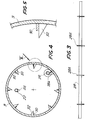
- suitable projections extend internally from the cylindrical shell of the rotor 3 and may consist of small bars or strips 30 (see in particular Figs. 4 and 5) which extend along the generatrices of the cylindrical shell of the rotor 3 at suitable distances from each other and with a mostly constant interval between them; these small bars 30 may be supported by triangular brackets 32.
- the small bars or strips 30 and the brackets 32 enable the bar 28 to be raised to a height at which the bar 28 spontaneously slips and falls by gravity into the lower part of the rotor containing the material, as a result of the inclination, during the rotation, of the projections which move the bar 28; the material is also partly raised during the rotation of the rotor, being engaged, in particular, by the small bars 30 and by the brackets 32 which are sharpened at their point of greatest projection; consequently, the material, made brittle by the low temperature, may be broken by the fall or may itself constitute an impact body for the material which is at that time in the lower part of the rotor and on to which these raised bodies may fall, in the same way as the bar 28 or other impact body.
- This aperture is more or less uncovered by the adjustable bulkhead 9, to regulate the material which is sent through the hopper 16 to a mill 36, for example a hammer mill, for subsequent further crushing of the material which arrives already roughly crushed by the impact body or bodies and by its passage through the rotor 3.
- Suitable inspection systems may be provided to monitor the operation of the rotor; in particular, a hatch 7A may be provided in the cap 7 and an inspection flange or hatch 9A may be provided in the bulkhead 9.
- the supports of the rotor 3 may be made with means (1X) allowing the inclination of the rotor to be adjusted according to the characteristics (which may be variable) of the waste to be treated and the desired capacity.
- the carrying fluid is advantageously free of moisture to prevent condensation and to ensure that the particles do not tend to agglomerate.
- a duct 40 leads from the mill 36 to a first classifier 42, in the lower part of which the duct 40 emerges; this duct has a rotary trap 40A - or other systems suitable for extracting the material without contact with the outside - to discharge the material finely crushed by the mill 36 for feeding to the said first classifier 42.
- a carrying fluid is fed to the classifier 42 from a duct 44 leading from a propulsive means 46, which may be a fan operating in closed circuit; the carrying fluid may be cooled by suitable continuous or intermittent injection of a cryogenic fluid.
- the duct 44 emerges in the lower part of the classifier 42, and the carrying fluid raises the lighter material to a transfer duct 48, while the heavier parts are collected in the base of the classifier 42 and are periodically discharged, for example by means of a rotary trap 42A.
- the duct 48 runs to the lower part of a second classifier 50 of the same shape as 42 and fitted with a rotary trap 50A for the discharge of the heavier parts of the material which arrives through the duct 48; these parts may be lighter plastics or other materials.
- a third classifier 54 which may be of the cyclone type for the recovery of the lighter parts, for example paper, through a bottom rotary trap 54A, while the carrying fluid from the third classifier 54 is returned along a duct 56 to the fan or other propulsive means 46, and may advantageously pass through a cooling system which may be combined with the refrigeration system for the cryogenic fluid which is fed to the rotor 3.
- One or more of the classifiers may be adjustable to permit the regulation of the sorting capacity.
- Fig. 6 shows an adjustable classifier, such as 42.
- a wall 42M is provided inside the parallelepipedal casing of the classifier, is hinged at 42N and can be adjusted with respect to its angular position by means of a system 42R, for example of the type consisting of a handwheel and threaded rod. By adjusting the movable wall 42M, it is possible to vary the specific sorting capacity.
- the system can be used to extract any material from any of the outlets, and ideally
- a filter may also be advantageously provided in the classifier circuit and after the classifiers, to prevent the recycling of any particles carried; the filter (or trap) can be emptied periodically, and may also be activated intermittently.
- a gravity, ballistic, or dimensional separator may be installed in series with the outlet rotary traps, at a temperature below 0°C, for further sorting.
- Suitable thermal insulation systems will be used to provide maximum energy savings, avoiding the dispersion of refrigerating units outside the components of the installation.
- the installation may be controlled by means of a suitable panel which enables the regular flow of the cryogenic fluid to be controlled as a function of the temperatures reached at the characteristic points of the installation; these temperatures may be measured by suitable sensors.
- the panel may permit the starting of the motors for the various circulations and the various movements and for the control of the rotary traps of the separators, for the operation of the crusher, and other purposes. Control of the pressures and speeds of fluids may also be provided, as well as a system of controlling the amount of solid municipal waste to be processed, as a function of various factors, including those relating to the temporary characteristics of the said solid municipal waste.
Landscapes
- Engineering & Computer Science (AREA)
- Food Science & Technology (AREA)
- Health & Medical Sciences (AREA)
- Toxicology (AREA)
- Disintegrating Or Milling (AREA)
- Separation By Low-Temperature Treatments (AREA)
- Processing Of Solid Wastes (AREA)
Applications Claiming Priority (2)
| Application Number | Priority Date | Filing Date | Title |
|---|---|---|---|
| ITFI930010 | 1993-01-28 | ||
| IT93FI10 IT1271454B (it) | 1993-01-28 | 1993-01-28 | Impianto di criotrasformazione e selezione di rifiuti solidi urbani. |
Publications (2)
| Publication Number | Publication Date |
|---|---|
| EP0610162A2 true EP0610162A2 (fr) | 1994-08-10 |
| EP0610162A3 EP0610162A3 (fr) | 1995-02-01 |
Family
ID=11350295
Family Applications (1)
| Application Number | Title | Priority Date | Filing Date |
|---|---|---|---|
| EP19940830027 Withdrawn EP0610162A3 (fr) | 1993-01-28 | 1994-01-27 | Installation pour la transformation cryogénique et le triage de déchets municipaux solides. |
Country Status (2)
| Country | Link |
|---|---|
| EP (1) | EP0610162A3 (fr) |
| IT (1) | IT1271454B (fr) |
Cited By (4)
| Publication number | Priority date | Publication date | Assignee | Title |
|---|---|---|---|---|
| EP0761310A1 (fr) * | 1995-09-07 | 1997-03-12 | Messer Griesheim Gmbh | Procédé et installation de broyage et de tamisage de matériau |
| EP0963825A1 (fr) * | 1998-06-10 | 1999-12-15 | Enea Ente Per Le Nuove Tecnologie, L'energia E L'ambiente | Procédé pour traiter de matières plastiques par voi mécanochimique |
| KR100301626B1 (ko) * | 1999-01-08 | 2001-09-22 | 공영조 | 초미립 분말의 생성방법 |
| WO2008109930A1 (fr) * | 2007-03-14 | 2008-09-18 | Sirol Holdings Pty Limited | Broyeur pour pneus |
Families Citing this family (3)
| Publication number | Priority date | Publication date | Assignee | Title |
|---|---|---|---|---|
| CN105772189B (zh) * | 2016-05-10 | 2018-12-04 | 中国科学院力学研究所 | 一种高压液态二氧化碳破碎铁矿石装置及方法 |
| CN109092454A (zh) * | 2018-07-17 | 2018-12-28 | 武汉中智德远科技开发有限公司 | 一种原料充分研磨用卧式过滤装置 |
| CN111589562A (zh) * | 2020-05-25 | 2020-08-28 | 广东先导先进材料股份有限公司 | 一种无氧高纯砷粉的制备方法 |
Family Cites Families (5)
| Publication number | Priority date | Publication date | Assignee | Title |
|---|---|---|---|---|
| DE2347108C3 (de) * | 1973-09-19 | 1980-02-14 | Vereinigte Aluminium-Werke Ag, 5300 Bonn | Verfahren zur Trennung von Metall und Kunststoff |
| GB1581030A (en) * | 1977-06-16 | 1980-12-10 | Boc Ltd | Comminution process |
| DE2839604A1 (de) * | 1978-09-12 | 1980-03-13 | Peter Voelskow | Trommelsieb |
| GB2132505B (en) * | 1982-12-20 | 1986-06-04 | Victor Lawson | Treatment of town's refuse |
| CA1328862C (fr) * | 1987-11-25 | 1994-04-26 | Andrew Paul Ondush | Methode et appareil de broyage fin |
-
1993
- 1993-01-28 IT IT93FI10 patent/IT1271454B/it active IP Right Grant
-
1994
- 1994-01-27 EP EP19940830027 patent/EP0610162A3/fr not_active Withdrawn
Cited By (5)
| Publication number | Priority date | Publication date | Assignee | Title |
|---|---|---|---|---|
| EP0761310A1 (fr) * | 1995-09-07 | 1997-03-12 | Messer Griesheim Gmbh | Procédé et installation de broyage et de tamisage de matériau |
| US5887803A (en) * | 1995-09-07 | 1999-03-30 | Messer Griesheim Gmbh | Process and apparatus for grinding and sifting a product |
| EP0963825A1 (fr) * | 1998-06-10 | 1999-12-15 | Enea Ente Per Le Nuove Tecnologie, L'energia E L'ambiente | Procédé pour traiter de matières plastiques par voi mécanochimique |
| KR100301626B1 (ko) * | 1999-01-08 | 2001-09-22 | 공영조 | 초미립 분말의 생성방법 |
| WO2008109930A1 (fr) * | 2007-03-14 | 2008-09-18 | Sirol Holdings Pty Limited | Broyeur pour pneus |
Also Published As
| Publication number | Publication date |
|---|---|
| IT1271454B (it) | 1997-05-28 |
| ITFI930010A1 (it) | 1994-07-28 |
| EP0610162A3 (fr) | 1995-02-01 |
| ITFI930010A0 (it) | 1993-01-28 |
Similar Documents
| Publication | Publication Date | Title |
|---|---|---|
| EP2735831A1 (fr) | Bande transporteuse de séchage et son système de production d'énergie thermoélectrique | |
| US5353997A (en) | Process for crushing raw lignite | |
| US3794251A (en) | Material reducing system and apparatus | |
| US10766038B2 (en) | Cryogenic grinding apparatus and process | |
| JP3199787B2 (ja) | ゴムを粉砕して粒子にするための装置 | |
| US4094769A (en) | Method and apparatus for retorting oil shale | |
| EP0610162A2 (fr) | Installation pour la transformation cryogénique et le triage de déchets municipaux solides | |
| US11248841B2 (en) | Coand{hacek over (a)}-effect vegetable material dryer | |
| WO2010019246A2 (fr) | Système et procédé de séchage à boucle fermée | |
| US6993857B2 (en) | Milling and drying apparatus incorporating a cyclone | |
| US3975263A (en) | Material separation apparatus and method | |
| US4962893A (en) | Process and device for cold milling | |
| KR930008282B1 (ko) | 플랜트의 재료분배장치 | |
| RU2459675C2 (ru) | Способ производства тонкопорошковых минеральных продуктов | |
| US4787152A (en) | Fluid-beds | |
| US3941687A (en) | Solids separation | |
| US2770543A (en) | Recirculating convection current cooler and method | |
| US7261208B2 (en) | Method and installation for drying sludge | |
| US20020078868A1 (en) | On-line remediation of high sulfur coal and control of coal-fired power plant feedstock | |
| US3383774A (en) | Apparatus and method for treating pulverulent or granular material | |
| US2796249A (en) | Apparatus for heating finely divided solid material | |
| EP0549137B1 (fr) | Procédé de broyage de matériaux | |
| US20060243830A1 (en) | Auto shredder air scrubber | |
| JP3341752B2 (ja) | 発泡断熱材中の発泡ガス回収方法 | |
| JP2535778B2 (ja) | 固形物の気流選別方法及び装置 |
Legal Events
| Date | Code | Title | Description |
|---|---|---|---|
| PUAI | Public reference made under article 153(3) epc to a published international application that has entered the european phase |
Free format text: ORIGINAL CODE: 0009012 |
|
| AK | Designated contracting states |
Kind code of ref document: A2 Designated state(s): AT BE CH DE DK ES FR GB GR IE LI LU MC NL PT SE |
|
| PUAL | Search report despatched |
Free format text: ORIGINAL CODE: 0009013 |
|
| AK | Designated contracting states |
Kind code of ref document: A3 Designated state(s): AT BE CH DE DK ES FR GB GR IE LI LU MC NL PT SE |
|
| 17P | Request for examination filed |
Effective date: 19950715 |
|
| RAP1 | Party data changed (applicant data changed or rights of an application transferred) |
Owner name: AIR LIQUIDE ITALIA S.R.L. Owner name: PRO.CO.GEN. PROGETTAZIONI E COSTRUZIONI GENERALI S |
|
| 17Q | First examination report despatched |
Effective date: 19970415 |
|
| STAA | Information on the status of an ep patent application or granted ep patent |
Free format text: STATUS: THE APPLICATION IS DEEMED TO BE WITHDRAWN |
|
| 18D | Application deemed to be withdrawn |
Effective date: 19970826 |